2007 ISUZU KB P190 service
[x] Cancel search: servicePage 3814 of 6020
Automatic Transmission – 4L60E – Electrical Diagnosis Page 7C2–28
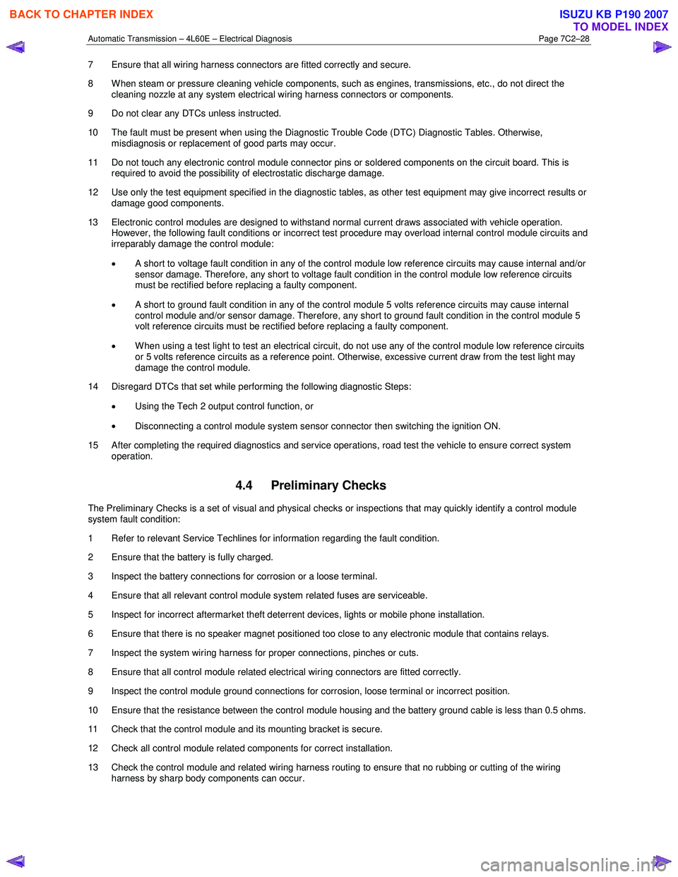
7 Ensure that all wiring harness connectors are fitted correctly and secure.
8 W hen steam or pressure cleaning vehicle components, such as engines, transmissions, etc., do not direct the cleaning nozzle at any system electrical wiring harness connectors or components.
9 Do not clear any DTCs unless instructed.
10 The fault must be present when using the Diagnostic Trouble Code (DTC) Diagnostic Tables. Otherwise, misdiagnosis or replacement of good parts may occur.
11 Do not touch any electronic control module connector pins or soldered components on the circuit board. This is required to avoid the possibility of electrostatic discharge damage.
12 Use only the test equipment specified in the diagnostic tables, as other test equipment may give incorrect results or damage good components.
13 Electronic control modules are designed to withstand normal current draws associated with vehicle operation. However, the following fault conditions or incorrect test procedure may overload internal control module circuits and
irreparably damage the control module:
• A short to voltage fault condition in any of the control module low reference circuits may cause internal and/or
sensor damage. Therefore, any short to voltage fault condition in the control module low reference circuits
must be rectified before replacing a faulty component.
• A short to ground fault condition in any of the control module 5 volts reference circuits may cause internal
control module and/or sensor damage. Therefore, any short to ground fault condition in the control module 5
volt reference circuits must be rectified before replacing a faulty component.
• W hen using a test light to test an electrical circuit, do not use any of the control module low reference circuits
or 5 volts reference circuits as a reference point. Otherwise, excessive current draw from the test light may
damage the control module.
14 Disregard DTCs that set while performing the following diagnostic Steps:
• Using the Tech 2 output control function, or
• Disconnecting a control module system sensor connector then switching the ignition ON.
15 After completing the required diagnostics and service operations, road test the vehicle to ensure correct system operation.
4.4 Preliminary Checks
The Preliminary Checks is a set of visual and physical checks or inspections that may quickly identify a control module
system fault condition:
1 Refer to relevant Service Techlines for information regarding the fault condition.
2 Ensure that the battery is fully charged.
3 Inspect the battery connections for corrosion or a loose terminal.
4 Ensure that all relevant control module system related fuses are serviceable.
5 Inspect for incorrect aftermarket theft deterrent devices, lights or mobile phone installation.
6 Ensure that there is no speaker magnet positioned too close to any electronic module that contains relays.
7 Inspect the system wiring harness for proper connections, pinches or cuts.
8 Ensure that all control module related electrical wiring connectors are fitted correctly.
9 Inspect the control module ground connections for corrosion, loose terminal or incorrect position.
10 Ensure that the resistance between the control module housing and the battery ground cable is less than 0.5 ohms.
11 Check that the control module and its mounting bracket is secure.
12 Check all control module related components for correct installation.
13 Check the control module and related wiring harness routing to ensure that no rubbing or cutting of the wiring harness by sharp body components can occur.
BACK TO CHAPTER INDEX
TO MODEL INDEX
ISUZU KB P190 2007
Page 3815 of 6020
Automatic Transmission – 4L60E – Electrical Diagnosis Page 7C2–29
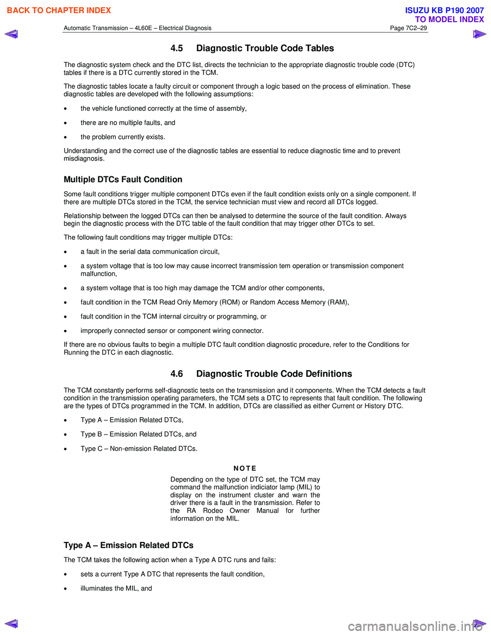
4.5 Diagnostic Trouble Code Tables
The diagnostic system check and the DTC list, directs the technician to the appropriate diagnostic trouble code (DTC)
tables if there is a DTC currently stored in the TCM.
The diagnostic tables locate a faulty circuit or component through a logic based on the process of elimination. These
diagnostic tables are developed with the following assumptions:
• the vehicle functioned correctly at the time of assembly,
• there are no multiple faults, and
• the problem currently exists.
Understanding and the correct use of the diagnostic tables are essential to reduce diagnostic time and to prevent
misdiagnosis.
Multiple DTCs Fault Condition
Some fault conditions trigger multiple component DTCs even if the fault condition exists only on a single component. If
there are multiple DTCs stored in the TCM, the service technician must view and record all DTCs logged.
Relationship between the logged DTCs can then be analysed to determine the source of the fault condition. Always
begin the diagnostic process with the DTC table of the fault condition that may trigger other DTCs to set.
The following fault conditions may trigger multiple DTCs:
• a fault in the serial data communication circuit,
• a system voltage that is too low may cause incorrect transmission tem operation or transmission component
malfunction,
• a system voltage that is too high may damage the TCM and/or other components,
• fault condition in the TCM Read Only Memory (ROM) or Random Access Memory (RAM),
• fault condition in the TCM internal circuitry or programming, or
• improperly connected sensor or component wiring connector.
If there are no obvious faults to begin a multiple DTC fault condition diagnostic procedure, refer to the Conditions for
Running the DTC in each diagnostic.
4.6 Diagnostic Trouble Code Definitions
The TCM constantly performs self-diagnostic tests on the transmission and it components. W hen the TCM detects a fault
condition in the transmission operating parameters, the TCM sets a DTC to represents that fault condition. The following
are the types of DTCs programmed in the TCM. In addition, DTCs are classified as either Current or History DTC.
• Type A – Emission Related DTCs,
• Type B – Emission Related DTCs, and
• Type C – Non-emission Related DTCs.
NOTE
Depending on the type of DTC set, the TCM may
command the malfunction indiciator lamp (MIL) to
display on the instrument cluster and warn the
driver there is a fault in the transmission. Refer to
the RA Rodeo Owner Manual for further
information on the MIL.
Type A – Emission Related DTCs
The TCM takes the following action when a Type A DTC runs and fails:
• sets a current Type A DTC that represents the fault condition,
• illuminates the MIL, and
BACK TO CHAPTER INDEX
TO MODEL INDEX
ISUZU KB P190 2007
Page 3822 of 6020
Automatic Transmission – 4L60E – Electrical Diagnosis Page 7C2–36
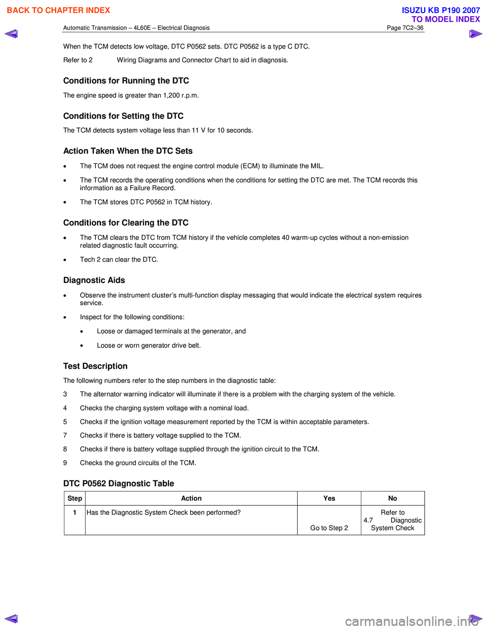
When the TCM detects low voltage, DTC P0562 sets. DTC P0562 is a type C DTC.
Refer to 2 W iring Diagrams and Connector Chart to aid in diagnosis.
Conditions for Running the DTC
The engine speed is greater than 1,200 r.p.m.
Conditions for Setting the DTC
The TCM detects system voltage less than 11 V for 10 seconds.
Action Taken When the DTC Sets
• The TCM does not request the engine control module (ECM) to illuminate the MIL.
• The TCM records the operating conditions when the conditions for setting the DTC are met. The TCM records this
information as a Failure Record.
• The TCM stores DTC P0562 in TCM history.
Conditions for Clearing the DTC
• The TCM clears the DTC from TCM history if the vehicle completes 40 warm-up cycles without a non-emission
related diagnostic fault occurring.
• Tech 2 can clear the DTC.
Diagnostic Aids
• Observe the instrument cluster’s multi-function display messaging that would indicate the electrical system requires
service.
• Inspect for the following conditions:
• Loose or damaged terminals at the generator, and
• Loose or worn generator drive belt.
Test Description
The following numbers refer to the step numbers in the diagnostic table:
3 The alternator warning indicator will illuminate if there is a problem with the charging system of the vehicle.
4 Checks the charging system voltage with a nominal load.
5 Checks if the ignition voltage measurement reported by the TCM is within acceptable parameters.
7 Checks if there is battery voltage supplied to the TCM.
8 Checks if there is battery voltage supplied through the ignition circuit to the TCM.
9 Checks the ground circuits of the TCM.
DTC P0562 Diagnostic Table
Step Action Yes No
1 Has the Diagnostic System Check been performed?
Go to Step 2 Refer to
4.7 Diagnostic
System Check
BACK TO CHAPTER INDEX
TO MODEL INDEX
ISUZU KB P190 2007
Page 3823 of 6020
Automatic Transmission – 4L60E – Electrical Diagnosis Page 7C2–37
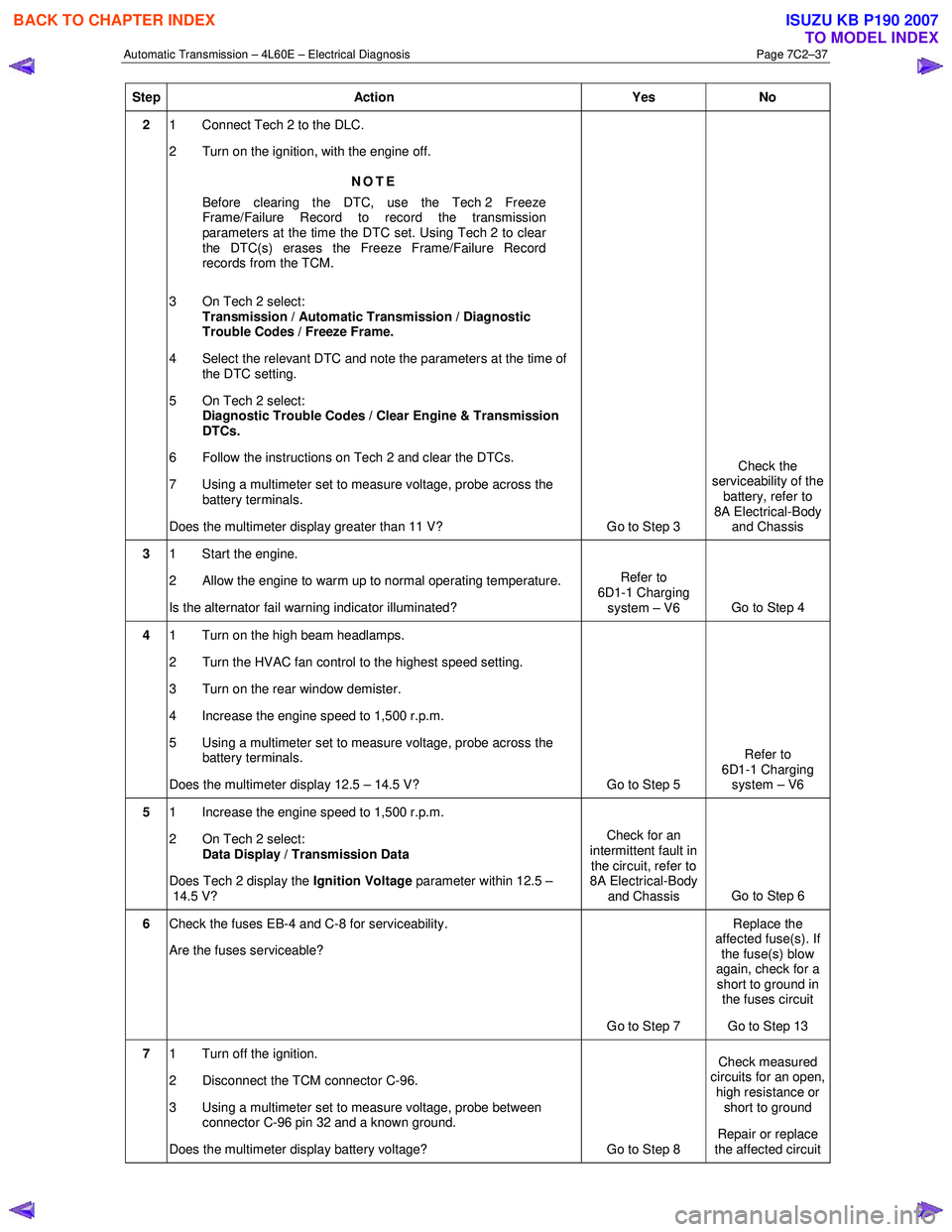
Step Action Yes No
2 1 Connect Tech 2 to the DLC.
2 Turn on the ignition, with the engine off.
NOTE
Before clearing the DTC, use the Tech 2 Freeze
Frame/Failure Record to record the transmission
parameters at the time the DTC set. Using Tech 2 to clear
the DTC(s) erases the Freeze Frame/Failure Record
records from the TCM.
3 On Tech 2 select: Transmission / Automatic Transmission / Diagnostic
Trouble Codes / Freeze Frame.
4 Select the relevant DTC and note the parameters at the time of the DTC setting.
5 On Tech 2 select:
Diagnostic Trouble Codes / Clear Engine & Transmission
DTCs.
6 Follow the instructions on Tech 2 and clear the DTCs.
7 Using a multimeter set to measure voltage, probe across the battery terminals.
Does the multimeter display greater than 11 V? Go to Step 3 Check the
serviceability of the battery, refer to
8A Electrical-Body and Chassis
3 1 Start the engine.
2 Allow the engine to warm up to normal operating temperature.
Is the alternator fail warning indicator illuminated? Refer to
6D1-1 Charging system – V6 Go to Step 4
4 1 Turn on the high beam headlamps.
2 Turn the HVAC fan control to the highest speed setting.
3 Turn on the rear window demister.
4 Increase the engine speed to 1,500 r.p.m.
5 Using a multimeter set to measure voltage, probe across the battery terminals.
Does the multimeter display 12.5 – 14.5 V? Go to Step 5 Refer to
6D1-1 Charging system – V6
5 1 Increase the engine speed to 1,500 r.p.m.
2 On Tech 2 select: Data Display / Transmission Data
Does Tech 2 display the Ignition Voltage parameter within 12.5 –
14.5 V? Check for an
intermittent fault in the circuit, refer to
8A Electrical-Body
and Chassis Go to Step 6
6
Check the fuses EB-4 and C-8 for serviceability.
Are the fuses serviceable?
Go to Step 7 Replace the
affected fuse(s). If the fuse(s) blow
again, check for a short to ground in the fuses circuit
Go to Step 13
7 1 Turn off the ignition.
2 Disconnect the TCM connector C-96.
3 Using a multimeter set to measure voltage, probe between connector C-96 pin 32 and a known ground.
Does the multimeter display battery voltage? Go to Step 8 Check measured
circuits for an open,
high resistance or short to ground
Repair or replace
the affected circuit
BACK TO CHAPTER INDEX
TO MODEL INDEX
ISUZU KB P190 2007
Page 3825 of 6020
Automatic Transmission – 4L60E – Electrical Diagnosis Page 7C2–39
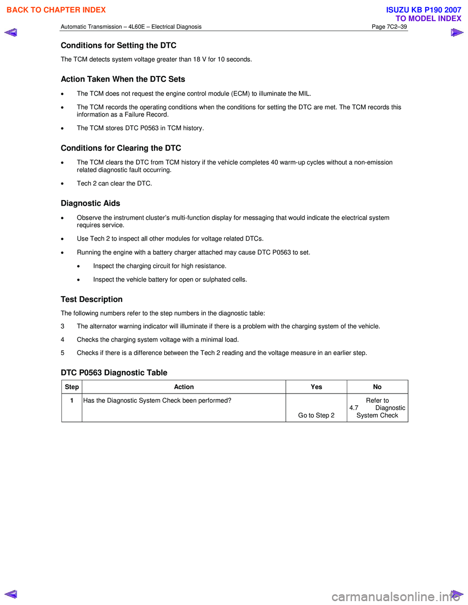
Conditions for Setting the DTC
The TCM detects system voltage greater than 18 V for 10 seconds.
Action Taken When the DTC Sets
•
The TCM does not request the engine control module (ECM) to illuminate the MIL.
• The TCM records the operating conditions when the conditions for setting the DTC are met. The TCM records this
information as a Failure Record.
• The TCM stores DTC P0563 in TCM history.
Conditions for Clearing the DTC
•
The TCM clears the DTC from TCM history if the vehicle completes 40 warm-up cycles without a non-emission
related diagnostic fault occurring.
• Tech 2 can clear the DTC.
Diagnostic Aids
• Observe the instrument cluster’s multi-function display for messaging that would indicate the electrical system
requires service.
• Use Tech 2 to inspect all other modules for voltage related DTCs.
• Running the engine with a battery charger attached may cause DTC P0563 to set.
• Inspect the charging circuit for high resistance.
• Inspect the vehicle battery for open or sulphated cells.
Test Description
The following numbers refer to the step numbers in the diagnostic table:
3 The alternator warning indicator will illuminate if there is a problem with the charging system of the vehicle.
4 Checks the charging system voltage with a minimal load.
5 Checks if there is a difference between the Tech 2 reading and the voltage measure in an earlier step.
DTC P0563 Diagnostic Table
Step Action Yes No
1 Has the Diagnostic System Check been performed?
Go to Step 2 Refer to
4.7 Diagnostic System Check
BACK TO CHAPTER INDEX
TO MODEL INDEX
ISUZU KB P190 2007
Page 3831 of 6020
Automatic Transmission – 4L60E – Electrical Diagnosis Page 7C2–45
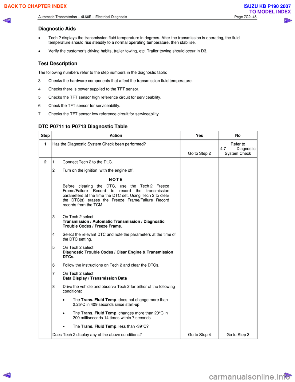
Diagnostic Aids
• Tech 2 displays the transmission fluid temperature in degrees. After the transmission is operating, the fluid
temperature should rise steadily to a normal operating temperature, then stabilise.
• Verify the customer's driving habits, trailer towing, etc. Trailer towing should occur in D3.
Test Description
The following numbers refer to the step numbers in the diagnostic table:
3 Checks the hardware components that affect the transmission fluid temperature.
4 Checks there is power supplied to the TFT sensor.
5 Checks the TFT sensor high reference circuit for serviceability.
6 Check the TFT sensor for serviceability.
7 Checks the TFT sensor low reference circuit for serviceability.
DTC P0711 to P0713 Diagnostic Table
Step Action Yes No
1 Has the Diagnostic System Check been performed?
Go to Step 2 Refer to
4.7 Diagnostic System Check
2 1 Connect Tech 2 to the DLC.
2 Turn on the ignition, with the engine off.
NOTE
Before clearing the DTC, use the Tech 2 Freeze
Frame/Failure Record to record the transmission
parameters at the time the DTC set. Using Tech 2 to clear
the DTC(s) erases the Freeze Frame/Failure Record
records from the TCM.
3 On Tech 2 select: Transmission / Automatic Transmission / Diagnostic
Trouble Codes / Freeze Frame.
4 Select the relevant DTC and note the parameters at the time of the DTC setting.
5 On Tech 2 select:
Diagnostic Trouble Codes / Clear Engine & Transmission
DTCs.
6 Follow the instructions on Tech 2 and clear the DTCs.
7 On Tech 2 select: Data Display / Transmission Data
8 Drive the vehicle and observe Tech 2 for either of the following conditions:
• The Trans. Fluid Temp . does not change more than
2.25°C in 409 seconds since start-up
• The Trans. Fluid Temp . changes more than 20°C in
200 milliseconds 14 times within 7 seconds
• The Trans. Fluid Temp . less than -39°C?
Does Tech 2 display any of the above conditions? Go to Step 4 Go to Step 3
BACK TO CHAPTER INDEX
TO MODEL INDEX
ISUZU KB P190 2007
Page 3834 of 6020
Automatic Transmission – 4L60E – Electrical Diagnosis Page 7C2–48
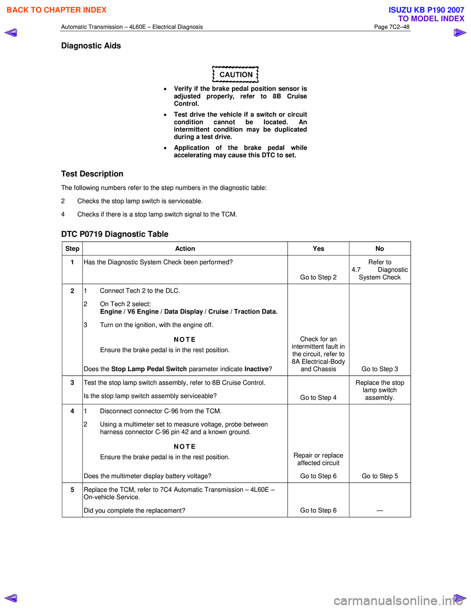
Diagnostic Aids
• Verify if the brake pedal position sensor is
adjusted properly, refer to 8B Cruise
Control.
• Test drive the vehicle if a switch or circuit
condition cannot be located. An
intermittent condition may be duplicated
during a test drive.
• Application of the brake pedal while
accelerating may cause this DTC to set.
Test Description
The following numbers refer to the step numbers in the diagnostic table:
2 Checks the stop lamp switch is serviceable.
4 Checks if there is a stop lamp switch signal to the TCM.
DTC P0719 Diagnostic Table
Step Action Yes No
1 Has the Diagnostic System Check been performed?
Go to Step 2 Refer to
4.7 Diagnostic System Check
2 1 Connect Tech 2 to the DLC.
2 On Tech 2 select: Engine / V6 Engine / Data Display / Cruise / Traction Data.
3 Turn on the ignition, with the engine off.
NOTE
Ensure the brake pedal is in the rest position.
Does the Stop Lamp Pedal Switch parameter indicate Inactive? Check for an
intermittent fault in
the circuit, refer to
8A Electrical-Body and Chassis Go to Step 3
3 Test the stop lamp switch assembly, refer to 8B Cruise Control.
Is the stop lamp switch assembly serviceable? Go to Step 4 Replace the stop
lamp switch
assembly.
4 1 Disconnect connector C-96 from the TCM.
2 Using a multimeter set to measure voltage, probe between harness connector C-96 pin 42 and a known ground.
NOTE
Ensure the brake pedal is in the rest position.
Does the multimeter display battery voltage? Repair or replace
affected circuit
Go to Step 6 Go to Step 5
5
Replace the TCM, refer to 7C4 Automatic Transmission – 4L60E –
On-vehicle Service.
Did you complete the replacement? Go to Step 6
—
BACK TO CHAPTER INDEX
TO MODEL INDEX
ISUZU KB P190 2007
Page 3838 of 6020
Automatic Transmission – 4L60E – Electrical Diagnosis Page 7C2–52
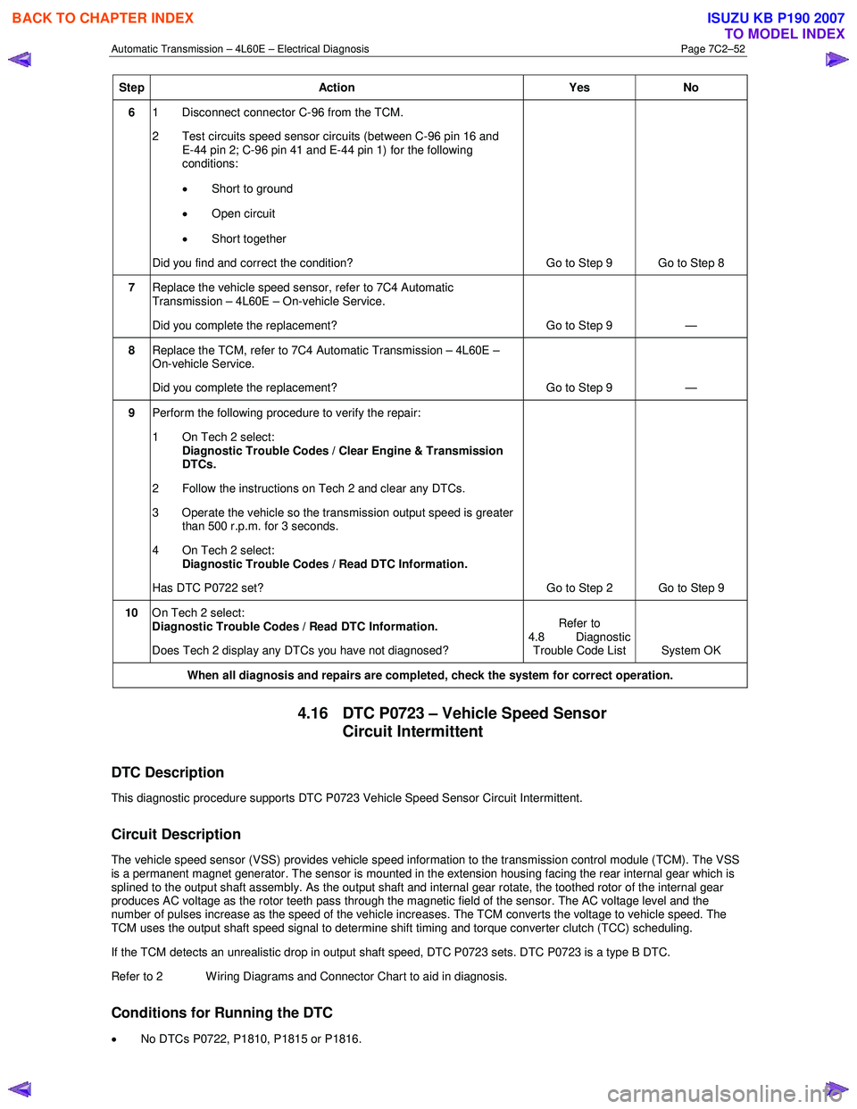
Step Action Yes No
6 1 Disconnect connector C-96 from the TCM.
2 Test circuits speed sensor circuits (between C-96 pin 16 and E-44 pin 2; C-96 pin 41 and E-44 pin 1) for the following
conditions:
• Short to ground
• Open circuit
• Short together
Did you find and correct the condition? Go to Step 9 Go to Step 8
7 Replace the vehicle speed sensor, refer to 7C4 Automatic
Transmission – 4L60E – On-vehicle Service.
Did you complete the replacement? Go to Step 9 —
8 Replace the TCM, refer to 7C4 Automatic Transmission – 4L60E –
On-vehicle Service.
Did you complete the replacement? Go to Step 9 —
9 Perform the following procedure to verify the repair:
1 On Tech 2 select: Diagnostic Trouble Codes / Clear Engine & Transmission
DTCs.
2 Follow the instructions on Tech 2 and clear any DTCs.
3 Operate the vehicle so the transmission output speed is greater than 500 r.p.m. for 3 seconds.
4 On Tech 2 select:
Diagnostic Trouble Codes / Read DTC Information.
Has DTC P0722 set? Go to Step 2 Go to Step 9
10 On Tech 2 select:
Diagnostic Trouble Codes / Read DTC Information.
Does Tech 2 display any DTCs you have not diagnosed? Refer to
4.8 Diagnostic Trouble Code List System OK
When all diagnosis and repairs are completed, check the system for correct operation.
4.16 DTC P0723 – Vehicle Speed Sensor
Circuit Intermittent
DTC Description
This diagnostic procedure supports DTC P0723 Vehicle Speed Sensor Circuit Intermittent.
Circuit Description
The vehicle speed sensor (VSS) provides vehicle speed information to the transmission control module (TCM). The VSS
is a permanent magnet generator. The sensor is mounted in the extension housing facing the rear internal gear which is
splined to the output shaft assembly. As the output shaft and internal gear rotate, the toothed rotor of the internal gear
produces AC voltage as the rotor teeth pass through the magnetic field of the sensor. The AC voltage level and the
number of pulses increase as the speed of the vehicle increases. The TCM converts the voltage to vehicle speed. The
TCM uses the output shaft speed signal to determine shift timing and torque converter clutch (TCC) scheduling.
If the TCM detects an unrealistic drop in output shaft speed, DTC P0723 sets. DTC P0723 is a type B DTC.
Refer to 2 W iring Diagrams and Connector Chart to aid in diagnosis.
Conditions for Running the DTC
• No DTCs P0722, P1810, P1815 or P1816.
BACK TO CHAPTER INDEX
TO MODEL INDEX
ISUZU KB P190 2007