Page 2954 of 6020
Engine Mechanical – V6 Page 6A1–177
Page 6A1–177
17 Reset the right-hand secondary timing chain
tensioner.
NOTE
To reset the tensioner, use a suitably sized flat
blade screwdriver (1) or Tool No. J 45027 to
wind the plunger in a clockwise direction, into
the tensioner shaft (2).
Figure 6A1 – 278
18 Install the tensioner s haft (1) into the right-hand
secondary timing chain tensioner body (2).
Figure 6A1 – 279
19 Compress the tensioner shaft into the body and lock the tensioner by inserting Tool No. EN 46112 into the
access hole in the side of the tensioner body.
20 Slowly release pressure on the right-hand secondary timing chain tensioner. The tensioner should remain
compressed.
Figure 6A1 – 280
BACK TO CHAPTER INDEX
TO MODEL INDEX
ISUZU KB P190 2007
Page 2955 of 6020

Engine Mechanical – V6 Page 6A1–178
Page 6A1–178
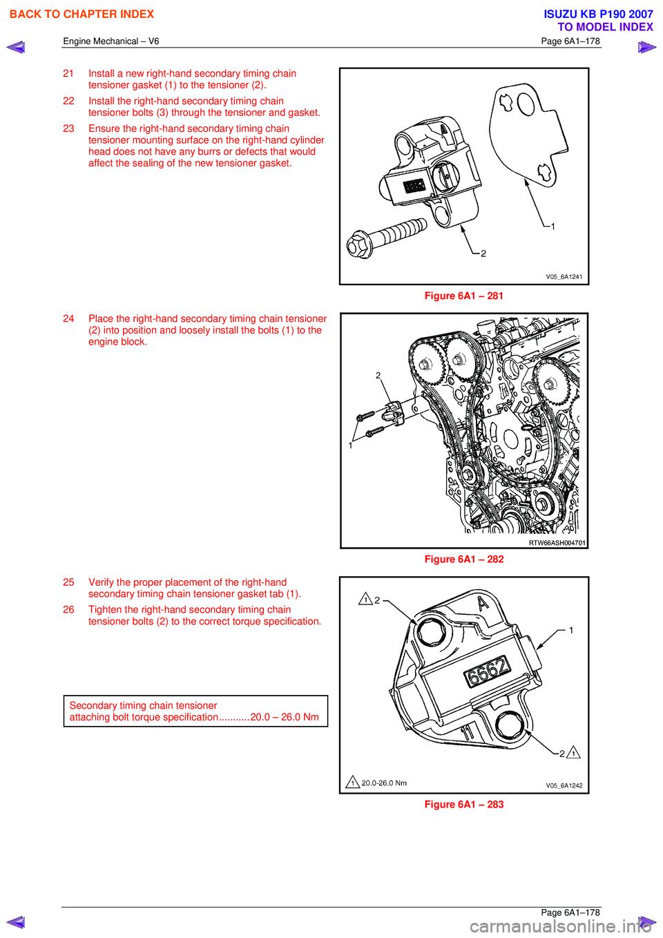
21 Install a new right-hand secondary timing chain
tensioner gasket (1) to the tensioner (2).
22 Install the right-hand secondary timing chain tensioner bolts (3) through the tensioner and gasket.
23 Ensure the right-hand secondary timing chain tensioner mounting surfac e on the right-hand cylinder
head does not have any burrs or defects that would
affect the sealing of the new tensioner gasket.
Figure 6A1 – 281
24 Place the right-hand secondar y timing chain tensioner
(2) into position and loosely install the bolts (1) to the
engine block.
Figure 6A1 – 282
25 Verify the proper plac ement of the right-hand
secondary timing chain tensioner gasket tab (1).
26 Tighten the right-hand secondary timing chain tensioner bolts (2) to the co rrect torque specification.
Secondary timing chain tensioner
attaching bolt torque spec ification ........... 20.0 – 26.0 Nm
Figure 6A1 – 283
BACK TO CHAPTER INDEX
TO MODEL INDEX
ISUZU KB P190 2007
Page 2956 of 6020
Engine Mechanical – V6 Page 6A1–179
Page 6A1–179
27 Release the right-hand timing chain tensioner (1) by
pulling out Tool No. EN 46112 (2) and unlocking the
tensioner plunger.
Figure 6A1 – 284
28 Verify all primary and secondary timing chain timing mark alignments (1 to 18).
29 Remove Tool No. EN 46105–1 and EN 46105-2 from the left and right-hand cylinder head camshafts.
30 Reinstall the spark plugs. Refer to Section 6C1-3
Engine Management – V6 – Service Operations.
31 Reinstall the engine front cover assembly, refer to 3.15 Front Cover Assembly .
Figure 6A1 – 285
BACK TO CHAPTER INDEX
TO MODEL INDEX
ISUZU KB P190 2007
Page 2962 of 6020
Engine Mechanical – V6 Page 6A1–185
Page 6A1–185
Reassemble
CAUTION
As there are no serviceable components
within the oil pump, a disassembled oil pump
must be replaced.
Reinstall
1 Align the oil pump gerotor with the crankshaft flats
and fit the oil pump assembly to the engine block.
2 Align the pump body (2) with the mounting holes in the cylinder block.
3 Install the oil pump bolt (1), three places, and tighten to the correct torque specification.
4 Install the primary timing chain, refer to 3.16 Timing
Chains, Tensioners, Shoes and Guides .
Oil pump attaching bolt torque
specificat ion ............................................ 20.0 – 26.0 Nm
Figure 6A1 – 297
BACK TO CHAPTER INDEX
TO MODEL INDEX
ISUZU KB P190 2007
Page 2972 of 6020

Engine Mechanical – V6 Page 6A1–195
Page 6A1–195
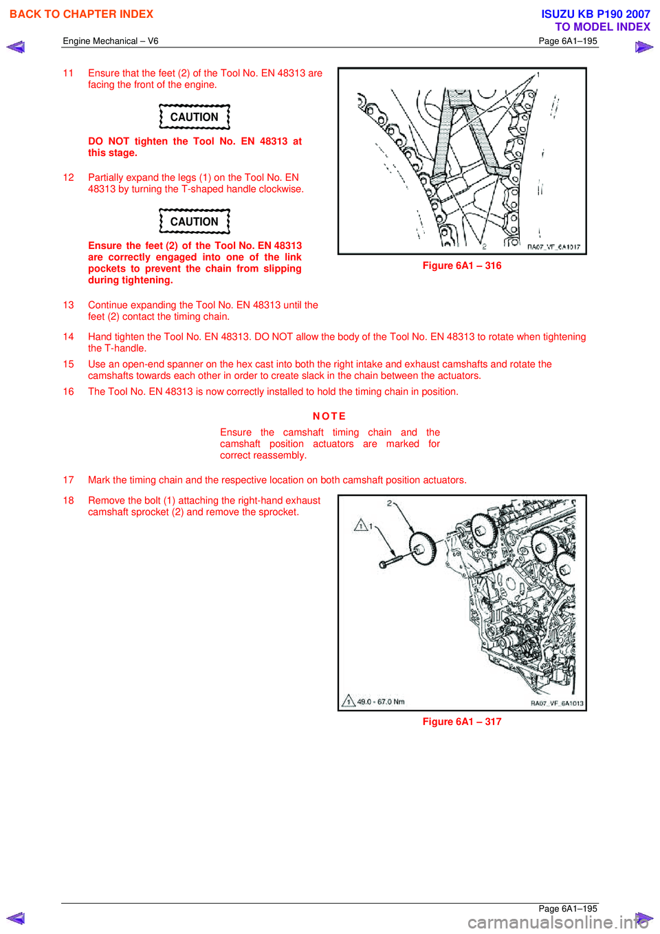
11 Ensure that the feet (2) of the Tool No. EN 48313 are
facing the front of the engine.
CAUTION
DO NOT tighten the Tool No. EN 48313 at
this stage.
12 Partially expand the legs (1) on the Tool No. EN 48313 by turning the T-shaped handle clockwise.
CAUTION
Ensure the feet (2) of the Tool No. EN 48313
are correctly engaged into one of the link
pockets to prevent the chain from slipping
during tightening.
13 Continue expanding the Tool No. EN 48313 until the feet (2) contact the timing chain.
Figure 6A1 – 316
14 Hand tighten the Tool No. EN 48313. DO NOT allow the body of the Tool No. EN 48313 to rotate when tightening
the T-handle.
15 Use an open-end spanner on the hex cast into both the right intake and exhaust camshafts and rotate the
camshafts towards each other in order to creat e slack in the chain between the actuators.
16 The Tool No. EN 48313 is now correctly inst alled to hold the timing chain in position.
NOTE
Ensure the camshaft timing chain and the
camshaft position actuators are marked for
correct reassembly.
17 Mark the timing chain and the respective location on both camshaft position actuators.
18 Remove the bolt (1) attaching the right-hand exhaust camshaft sprocket (2) and remove the sprocket.
Figure 6A1 – 317
BACK TO CHAPTER INDEX
TO MODEL INDEX
ISUZU KB P190 2007
Page 2975 of 6020

Engine Mechanical – V6 Page 6A1–198
Page 6A1–198
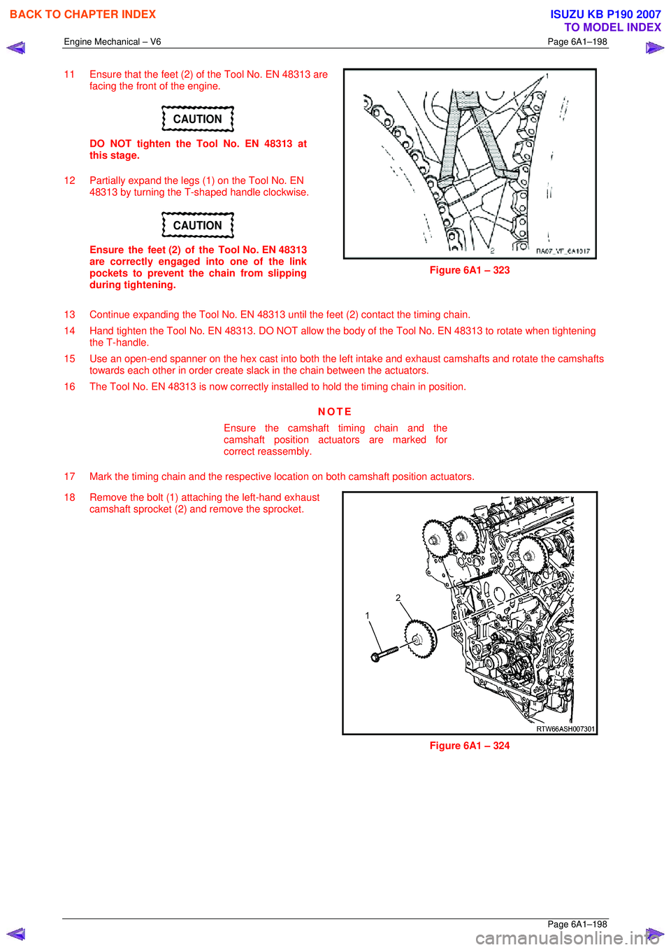
11 Ensure that the feet (2) of the Tool No. EN 48313 are
facing the front of the engine.
CAUTION
DO NOT tighten the Tool No. EN 48313 at
this stage.
12 Partially expand the legs (1) on the Tool No. EN 48313 by turning the T-shaped handle clockwise.
CAUTION
Ensure the feet (2) of the Tool No. EN 48313
are correctly engaged into one of the link
pockets to prevent the chain from slipping
during tightening.
Figure 6A1 – 323
13 Continue expanding the Tool No. EN 48313 until the feet (2) contact the timing chain.
14 Hand tighten the Tool No. EN 48313. DO NOT allow the body of the Tool No. EN 48313 to rotate when tightening
the T-handle.
15 Use an open-end spanner on the hex cast into both the left intake and exhaust camshafts and rotate the camshafts
towards each other in order create sla ck in the chain between the actuators.
16 The Tool No. EN 48313 is now correctly inst alled to hold the timing chain in position.
NOTE
Ensure the camshaft timing chain and the
camshaft position actuators are marked for
correct reassembly.
17 Mark the timing chain and the respective location on both camshaft position actuators.
18 Remove the bolt (1) attaching the left-hand exhaust camshaft sprocket (2) and remove the sprocket.
Figure 6A1 – 324
BACK TO CHAPTER INDEX
TO MODEL INDEX
ISUZU KB P190 2007
Page 3007 of 6020
Engine Mechanical – V6 Page 6A1–230
Page 6A1–230
Assemble
1 Install the cylinder head coolant threaded plugs (1)
and tighten to the correct torque specification.
Cylinder head thre aded plug .............................. 31.0 Nm
Figure 6A1 – 388
2 Install the cylinder head oil gallery expansion plugs (1).
Figure 6A1 – 389
CAUTION
• Never reuse a valve stem oil seal. Always
use new seals when assembling the
cylinder head.
• Force should only be applied to the valve
spring contact area of the new valve stem
oil seal during installation.
3 Fit the valve stem oil seal s onto the guides using Tool
No. EN-46116 (1).
4 Push and twist the valve stem oil seal into position on the valve guide until the s eal positively locks on the
guide using Tool No. EN-46116.
5 Lubricate the valve stem and valve guide ID with clean engine oil.
Figure 6A1 – 390
BACK TO CHAPTER INDEX
TO MODEL INDEX
ISUZU KB P190 2007
Page 3010 of 6020

Engine Mechanical – V6 Page 6A1–233
Page 6A1–233
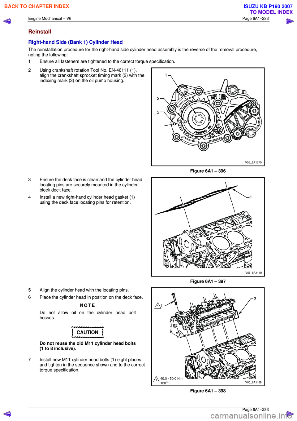
Reinstall
Right-hand Side (Bank 1) Cylinder Head
The reinstallation procedure for the right-hand side cylinder head assembly is the reverse of the removal procedure,
noting the following:
1 Ensure all fasteners are tightened to the correct torque specification.
2 Using crankshaft rotation Tool No. EN-46111 (1), align the crankshaft sprocket timing mark (2) with the
indexing mark (3) on the oil pump housing.
Figure 6A1 – 396
3 Ensure the deck face is clean and the cylinder head locating pins are securely mounted in the cylinder
block deck face.
4 Install a new right-hand cylinder head gasket (1) using the deck face locating pins for retention.
Figure 6A1 – 397
5 Align the cylinder head with the locating pins.
6 Place the cylinder head in position on the deck face.
NOTE
Do not allow oil on the cylinder head bolt
bosses.
CAUTION
Do not reuse the old M11 cylinder head bolts
(1 to 8 inclusive).
7 Install new M11 cylinder head bolts (1) eight places and tighten in the sequence shown and to the correct
torque specification.
Figure 6A1 – 398
BACK TO CHAPTER INDEX
TO MODEL INDEX
ISUZU KB P190 2007