Page 3034 of 6020

Engine Mechanical – V6 Page 6A1–257
Page 6A1–257
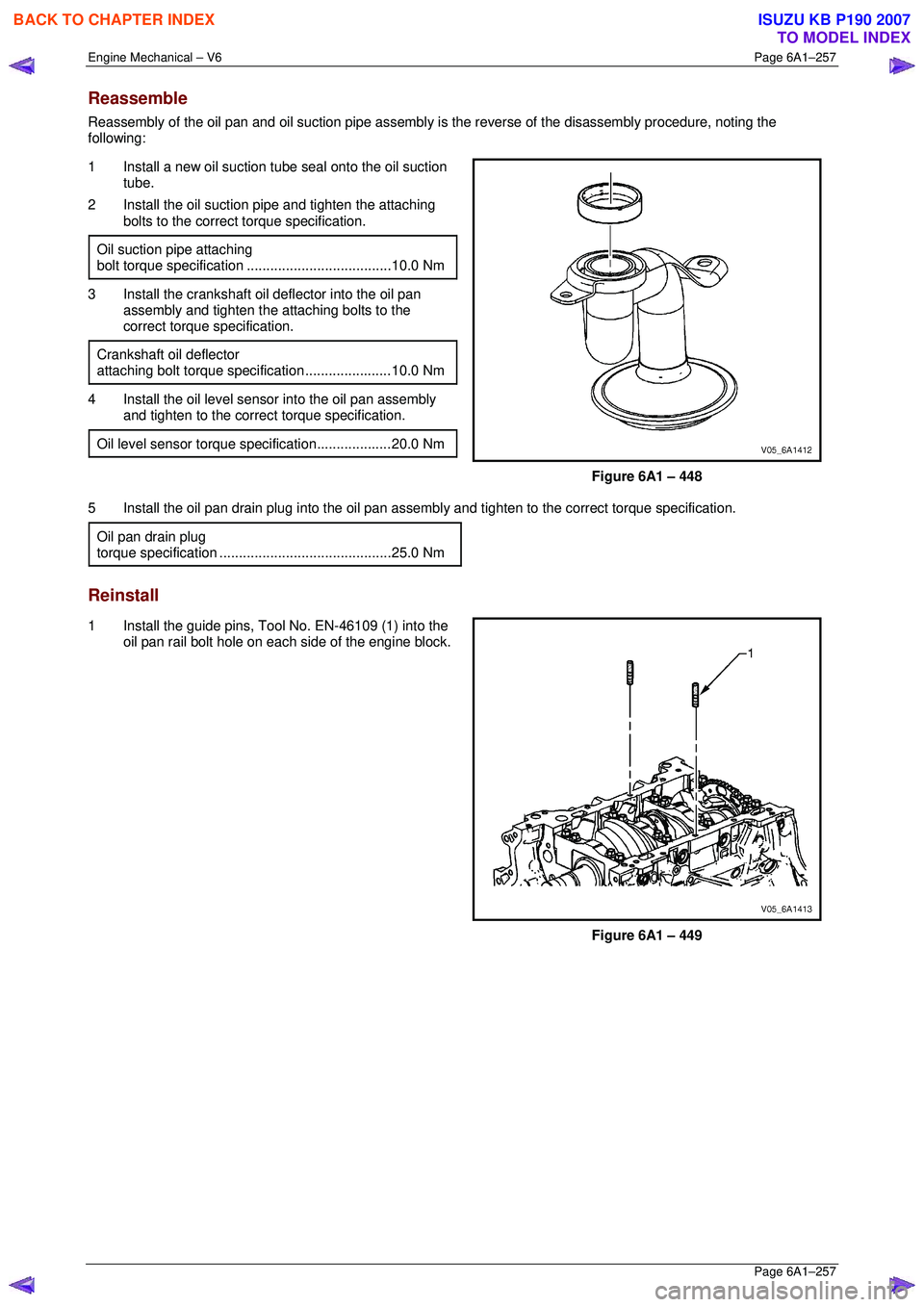
Reassemble
Reassembly of the oil pan and oil suction pipe assembly is the reverse of the disassembly procedure, noting the
following:
1 Install a new oil suction t ube seal onto the oil suction
tube.
2 Install the oil suction pipe and tighten the attaching bolts to the correct torque specification.
Oil suction pipe attaching
bolt torque specif ication ..................................... 10.0 Nm
3 Install the crankshaft oil deflector into the oil pan
assembly and tighten the attaching bolts to the
correct torque specification.
Crankshaft oil deflector
attaching bolt torque specification ......................10.0 Nm
4 Install the oil level sensor into the oil pan assembly
and tighten to the correct torque specification.
Oil level sensor torque specification...................20.0 Nm
Figure 6A1 – 448
5 Install the oil pan drain plug into the oil pan assemb ly and tighten to the correct torque specification.
Oil pan drain plug
torque specificat ion ............................................ 25.0 Nm
Reinstall
1 Install the guide pins, Tool No. EN-46109 (1) into the
oil pan rail bolt hole on each side of the engine block.
Figure 6A1 – 449
BACK TO CHAPTER INDEX
TO MODEL INDEX
ISUZU KB P190 2007
Page 3035 of 6020
Engine Mechanical – V6 Page 6A1–258
Page 6A1–258
2 Place a 3mm bead (1) of RTV sealant on the cylinder
block pan rail and crankshaft rear oil seal housing to
oil pan mating surfaces.
3 Position the oil pan onto the cylinder block.
4 Remove the guide pins, Tool No. EN-46109 from the cylinder block.
Figure 6A1 – 450
5 Loosely install the oil pan bolts.
6 Tighten the oil pan attaching bolts to the correct torque specification and in the sequence shown.
Oil pan to cylinder block attaching
bolt (1 – 11) torque specif ication............. 20.0 – 26.0 Nm
Oil pan to crankshaft rear oil
seal housing attaching bolt (12 – 13)
torque specificatio n ................................... 8. 0 – 12.0 Nm
Figure 6A1 – 451
BACK TO CHAPTER INDEX
TO MODEL INDEX
ISUZU KB P190 2007
Page 3039 of 6020
Engine Mechanical – V6 Page 6A1–262
Page 6A1–262
4.4 Crankshaft Rear Seal and Plate
Assembly
Remove
1 Remove the engine assembly, refer to 4.1 Engine .
2 Remove the flexplat e assembly, refer to 4.3 Flexplate Assembly .
3 Remove the engine oil pan assembly, refer to 4.2 Oil Pan and Oil Pump Suction Pipe Assembly.
4 Remove the five bolts (1) attaching the crankshaft rear seal housing to the rear of the cylinder block (2).
Figure 6A1 – 457
5 Shear the RTV sealant usi ng the prise points located
at the edge of the crankshaft rear oil seal housing,
Figure 6A1 – 458
BACK TO CHAPTER INDEX
TO MODEL INDEX
ISUZU KB P190 2007
Page 3040 of 6020
Engine Mechanical – V6 Page 6A1–263
Page 6A1–263
6 Remove the crankshaft rear oil seal housing (1) from
the cylinder block (2).
Figure 6A1 – 459
Reinstall
1 Install the guide pins, Tool No. EN-46109 (1) into the two crankshaft rear oil seal housing bolt holes of the
cylinder block (2).
Figure 6A1 – 460
2 Apply a 3mm bead (1) of RTV sealant to the crankshaft rear oil seal housing.
Figure 6A1 – 461
BACK TO CHAPTER INDEX
TO MODEL INDEX
ISUZU KB P190 2007
Page 3041 of 6020
Engine Mechanical – V6 Page 6A1–264
Page 6A1–264
3 Install the crankshaft rear oil seal housing (1) to the
cylinder block (2).
NOTE
• Do not allow any engine oil onto the cylinder
block mating surface, where the crankshaft
rear oil seal housing is to be installed.
• A seal-protector is provided with the new
crankshaft rear seal and housing assembly.
Do not remove the seal protector from the
crankshaft rear oil seal housing until the
crankshaft rear oil seal housing is fully in
position.
4 Remove the guide pins from the cylinder block.
Figure 6A1 – 462
5 Install the crankshaft rear oil seal housing attaching bolts (1) to the cylinder block (2) and tighten to the
correct torque specification.
Crankshaft rear oil seal housing
attaching bolt torque spec ification ............. 8.0 – 12.0 Nm
Figure 6A1 – 463
BACK TO CHAPTER INDEX
TO MODEL INDEX
ISUZU KB P190 2007
Page 3047 of 6020

Engine Mechanical – V6 Page 6A1–270
Page 6A1–270
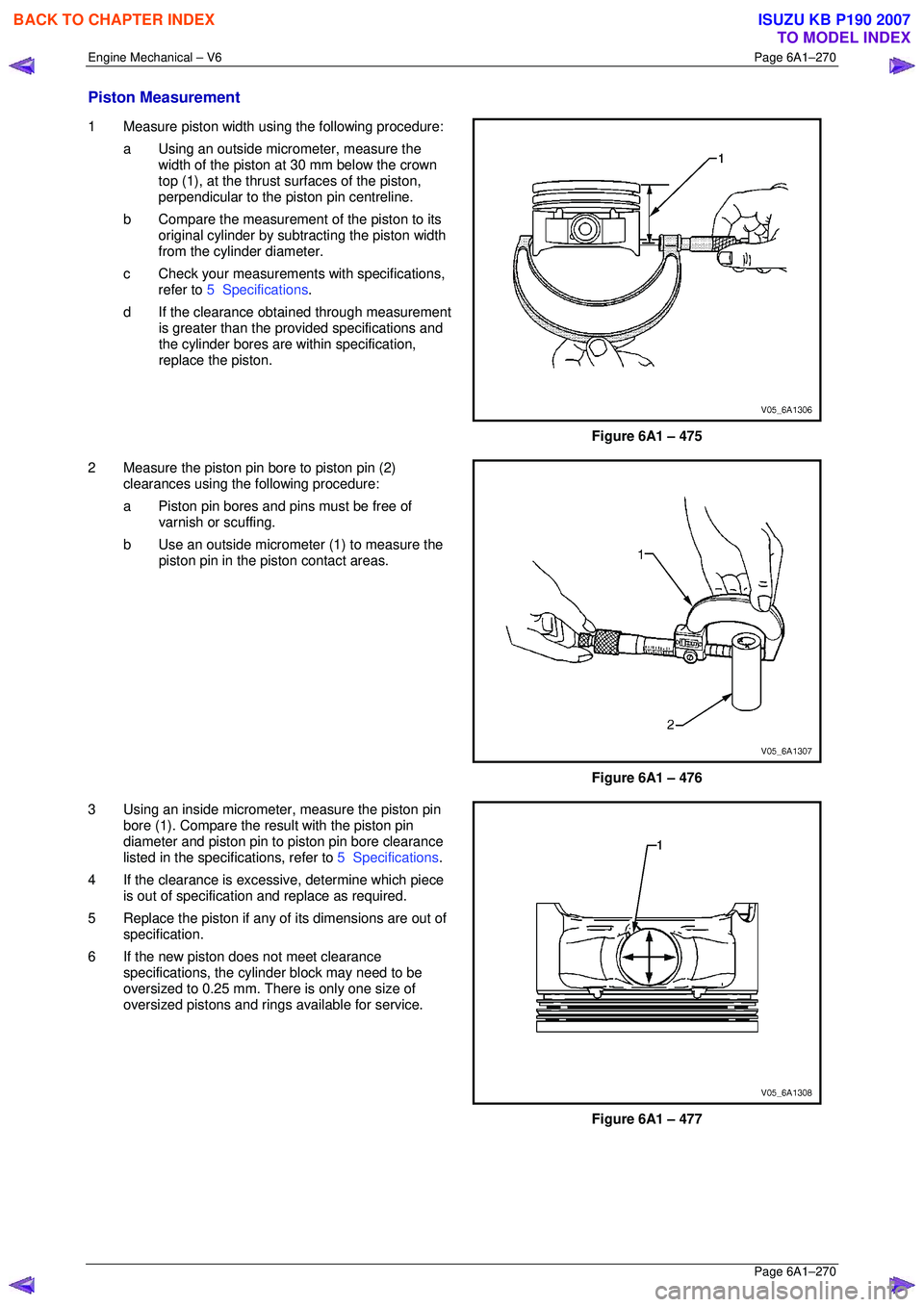
Piston Measurement
1 Measure piston width using the following procedure:
a Using an outside micr ometer, measure the
width of the piston at 30 mm below the crown
top (1), at the thrust surfaces of the piston,
perpendicular to the piston pin centreline.
b Compare the measurement of the piston to its
original cylinder by subtracting the piston width
from the cylinder diameter.
c Check your measurements with specifications, refer to 5 Specifications .
d If the clearance obtai ned through measurement
is greater than the prov ided specifications and
the cylinder bores are wi thin specification,
replace the piston.
Figure 6A1 – 475
2 Measure the piston pin bore to piston pin (2) clearances using the following procedure:
a Piston pin bores and pins must be free of varnish or scuffing.
b Use an outside micrometer (1) to measure the
piston pin in the piston contact areas.
Figure 6A1 – 476
3 Using an inside micrometer , measure the piston pin
bore (1). Compare the resu lt with the piston pin
diameter and piston pin to piston pin bore clearance
listed in the specifications, refer to 5 Specifications.
4 If the clearance is excessive, determine which piece is out of specification and replace as required.
5 Replace the piston if any of its dimensions are out of
specification.
6 If the new piston does not meet clearance specifications, the cylinder block may need to be
oversized to 0.25 mm. There is only one size of
oversized pistons and rings available for service.
Figure 6A1 – 477
BACK TO CHAPTER INDEX
TO MODEL INDEX
ISUZU KB P190 2007
Page 3048 of 6020

Engine Mechanical – V6 Page 6A1–271
Page 6A1–271
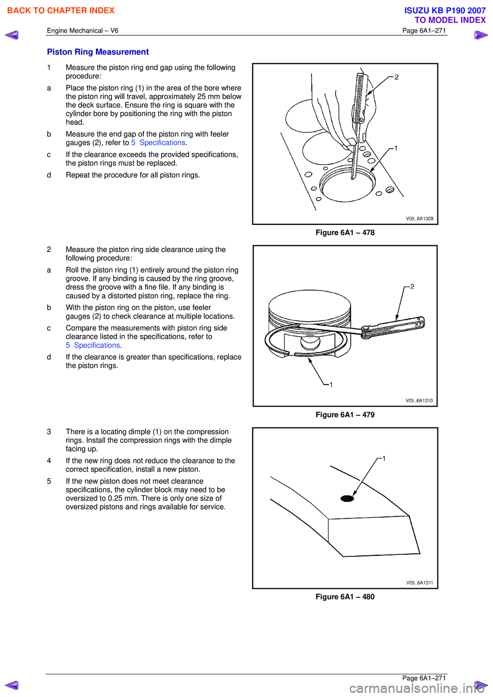
Piston Ring Measurement
1 Measure the piston ring end gap using the following
procedure:
a Place the piston ring (1) in the area of the bore where
the piston ring will travel, approximately 25 mm below
the deck surface. Ensure t he ring is square with the
cylinder bore by positioning the ring with the piston
head.
b Measure the end gap of the piston ring with feeler
gauges (2), refer to 5 Specifications.
c If the clearance exceeds t he provided specifications,
the piston rings must be replaced.
d Repeat the procedure for all piston rings.
Figure 6A1 – 478
2 Measure the piston ring side clearance using the
following procedure:
a Roll the piston ring (1) ent irely around the piston ring
groove. If any binding is c aused by the ring groove,
dress the groove with a fine file. If any binding is
caused by a distorted piston ring, replace the ring.
b With the piston ring on the piston, use feeler
gauges (2) to check clearance at multiple locations.
c Compare the measurement s with piston ring side
clearance listed in the spec ifications, refer to
5 Specifications .
d If the clearance is greater than specifications, replace
the piston rings.
Figure 6A1 – 479
3 There is a locating dimple (1) on the compression rings. Install the compression rings with the dimple
facing up.
4 If the new ring does not r educe the clearance to the
correct specification, install a new piston.
5 If the new piston does not meet clearance specifications, the cylinder block may need to be
oversized to 0.25 mm. There is only one size of
oversized pistons and rings available for service.
Figure 6A1 – 480
BACK TO CHAPTER INDEX
TO MODEL INDEX
ISUZU KB P190 2007
Page 3053 of 6020

Engine Mechanical – V6 Page 6A1–276
Page 6A1–276
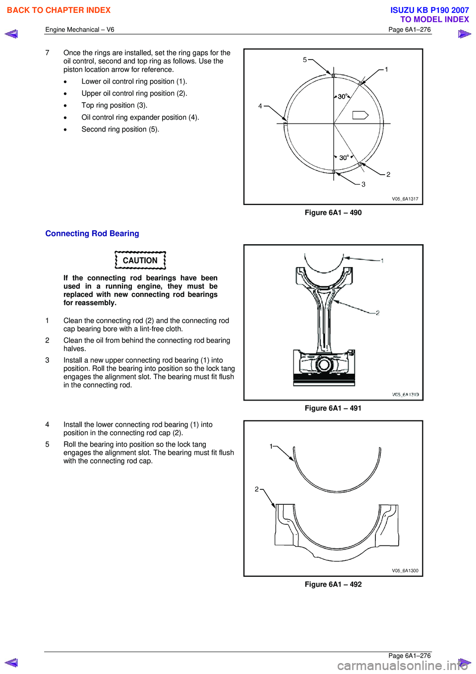
7 Once the rings are installed, set the ring gaps for the
oil control, second and top ring as follows. Use the
piston location arrow for reference.
• Lower oil control ring position (1).
• Upper oil control ring position (2).
• Top ring position (3).
• Oil control ring ex pander position (4).
• Second ring position (5).
Figure 6A1 – 490
Connecting Rod Bearing
CAUTION
If the connecting rod bearings have been
used in a running engine, they must be
replaced with new connecting rod bearings
for reassembly.
1 Clean the connecting rod (2) and the connecting rod
cap bearing bore with a lint-free cloth.
2 Clean the oil from behind the connecting rod bearing halves.
3 Install a new upper connecting rod bearing (1) into position. Roll the bearing into position so the lock tang
engages the alignment slot. The bearing must fit flush
in the connecting rod.
Figure 6A1 – 491
4 Install the lower connecting rod bearing (1) into position in the connecting rod cap (2).
5 Roll the bearing into position so the lock tang engages the alignment slot. The bearing must fit flush
with the connecting rod cap.
Figure 6A1 – 492
BACK TO CHAPTER INDEX
TO MODEL INDEX
ISUZU KB P190 2007