2007 ISUZU KB P190 lock
[x] Cancel search: lockPage 3054 of 6020
Engine Mechanical – V6 Page 6A1–277
Page 6A1–277
Reinstall
Piston Connecting Rod and Connecting Rod Bearing Installation
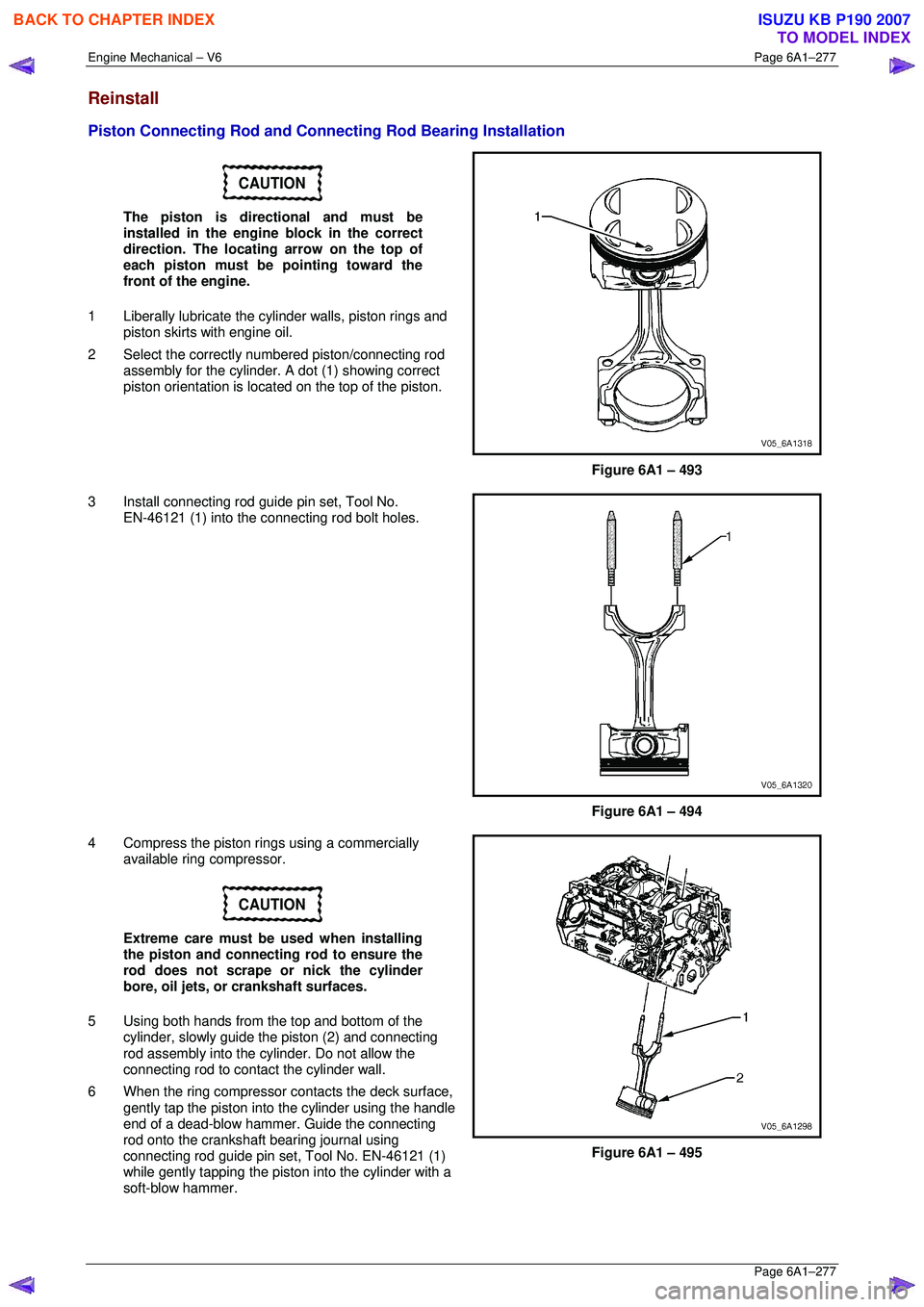
CAUTION
The piston is directional and must be
installed in the engine block in the correct
direction. The locating arrow on the top of
each piston must be pointing toward the
front of the engine.
1 Liberally lubricate the cy linder walls, piston rings and
piston skirts with engine oil.
2 Select the correctly numbered piston/connecting rod
assembly for the cylinder. A dot (1) showing correct
piston orientation is locat ed on the top of the piston.
Figure 6A1 – 493
3 Install connecting rod guide pin set, Tool No. EN-46121 (1) into the connecting rod bolt holes.
Figure 6A1 – 494
4 Compress the piston rings using a commercially available ring compressor.
CAUTION
Extreme care must be used when installing
the piston and connecting rod to ensure the
rod does not scrape or nick the cylinder
bore, oil jets, or crankshaft surfaces.
5 Using both hands from the top and bottom of the cylinder, slowly guide the piston (2) and connecting
rod assembly into the cylinder. Do not allow the
connecting rod to contact the cylinder wall.
6 When the ring compressor c ontacts the deck surface,
gently tap the piston into the cylinder using the handle
end of a dead-blow hammer. Guide the connecting
rod onto the crankshaft bearing journal using
connecting rod guide pin set, Tool No. EN-46121 (1)
while gently tapping the piston into the cylinder with a
soft-blow hammer.
Figure 6A1 – 495
BACK TO CHAPTER INDEX
TO MODEL INDEX
ISUZU KB P190 2007
Page 3055 of 6020
Engine Mechanical – V6 Page 6A1–278
Page 6A1–278
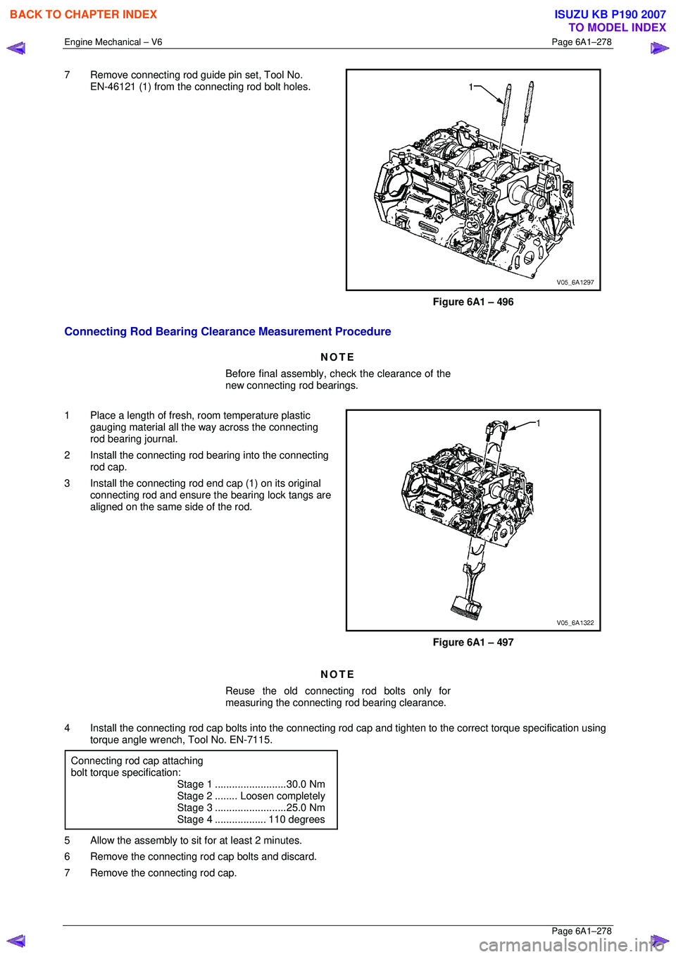
7 Remove connecting rod guide pin set, Tool No.
EN-46121 (1) from the connecting rod bolt holes.
Figure 6A1 – 496
Connecting Rod Bearing Clearance Measurement Procedure
NOTE
Before final assembly, check the clearance of the
new connecting rod bearings.
1 Place a length of fresh, room temperature plastic
gauging material all the way across the connecting
rod bearing journal.
2 Install the connecting rod bearing into the connecting
rod cap.
3 Install the connecting rod end cap (1) on its original
connecting rod and ensure t he bearing lock tangs are
aligned on the same side of the rod.
Figure 6A1 – 497
NOTE
Reuse the old connecting rod bolts only for
measuring the connecting rod bearing clearance.
4 Install the connecting rod cap bolts in to the connecting rod cap and tighten to the correct torque specification using
torque angle wrench, Tool No. EN-7115.
Connecting rod cap attaching
bolt torque specification:
Stage 1 .........................30.0 Nm
Stage 2 ........Loosen completely
Stage 3 .........................25.0 Nm
Stage 4 ..................110 degrees
5 Allow the assembly to sit for at least 2 minutes.
6 Remove the connecting rod cap bolts and discard.
7 Remove the connecting rod cap.
BACK TO CHAPTER INDEX
TO MODEL INDEX
ISUZU KB P190 2007
Page 3056 of 6020
Engine Mechanical – V6 Page 6A1–279
Page 6A1–279
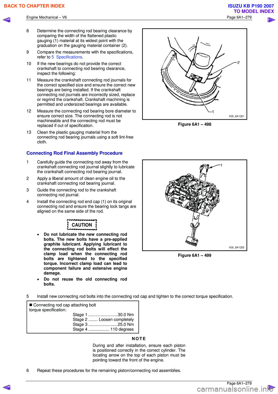
8 Determine the connecting rod bearing clearance by
comparing the width of the flattened plastic
gauging (1) material at its widest point with the
graduation on the gauging mate rial container (2).
9 Compare the measurements with the specifications,
refer to 5 Specifications .
10 If the new bearings do not provide the correct crankshaft to connecting rod bearing clearance,
inspect the following:
11 Measure the crankshaft connecting rod journals for the correct specified size and ensure the correct new
bearings are being installed. If the crankshaft
connecting rod journals are in correctly sized, replace
or regrind the crankshaft. Crankshaft machining is
permitted and undersized bearings are available.
12 Measure the connecting rod bearing bore diameter to
ensure correct size. The connecting rod is not
machineable and the connecting rod must be
replaced if out of specification.
13 Clean the plastic gauging material from the connecting rod bearing journals using a soft lint-free
cloth.
Figure 6A1 – 498
Connecting Rod Final Assembly Procedure
1 Carefully guide the connecting rod away from the crankshaft connecting rod journal slightly to lubricate
the crankshaft connecting rod bearing journal.
2 Apply a liberal amount of clean engine oil to the crankshaft connecting rod bearing journal.
3 Guide the connecting rod to the crankshaft connecting rod journal.
4 Install the connecting rod end cap (1) on its original
connecting rod and ensure t he bearing lock tangs are
aligned on the same side of the rod.
CAUTION
• Do not lubricate the new connecting rod
bolts. The new bolts have a pre-applied
graphite lubricant. Applying lubricant to
the connecting rod bolts will effect the
clamp load when the connecting rod
bolts are tightened to the specified
torque. Incorrect clamp load can lead to
component failure and extensive engine
damage.
• Do not reuse the old connecting rod
bolts.
Figure 6A1 – 499
5 Install new connecting rod bolts into the connecting r od cap and tighten to the correct torque specification.
�„ Connecting rod cap attaching bolt
torque specification:
Stage 1 .........................30.0 Nm
Stage 2 ........Loosen completely
Stage 3 .........................25.0 Nm
Stage 4 ..................110 degrees
NOTE
During and after installation, ensure each piston
is positioned correctly in the correct cylinder. The
locating arrow on the top of each piston must be
pointing toward the front of the engine.
6 Repeat these procedures for the rema ining piston/connecting rod assemblies.
BACK TO CHAPTER INDEX
TO MODEL INDEX
ISUZU KB P190 2007
Page 3058 of 6020

Engine Mechanical – V6 Page 6A1–281
Page 6A1–281
4.6 Crankshaft and Main Bearings
1 Remove the engine assembly, refer to 4.1 Engine .
2 Remove both cylinder head assemblies, refer to 3.22 Cylinder Head Assembly.
3 Remove the oil pan assembly, refer to 4.2 Oil Pan and Oil Pump Suction Pipe Assembly .
4 Remove the piston and connecting rod assemblies, refer to 4.5 Pistons, Pins, Rings, Connecting Rods and Big-
end Bearings .
5 Remove the oil pump assembly, refer to 3.17 Oil Pump Assembly.
6 Remove the crankshaft rear oil seal and plate assembly, refer to 4.4 Crankshaft Rear Seal and Plate Assembly .
7 Remove the crankshaft position sensor, refer to Section 6C1-3 Engine Management – V6 – Service Operations.
Crankshaft End Play Measurement
1 Place a dial indicator at the end of the crankshaft nose.
2 Gently force the crankshaft towards the front and rear of the cylinder block with a lever while monitoring the
movement of the dial indicator.
3 The crankshaft endplay should not exceed specifications, refer to 5 Specifications.
4 If the specifications are ex ceeded, inspect the thrust bearing thrust outer diameter and the crankshaft thrust wall for
wear and/or excessive runout. Compare the va lues with the specifications, refer to 5 Specifications.
5 Replace the thrust bearing or crankshaft as required.
Remove
1 Remove the crankshaft bearing cap side bolts (3).
CAUTION
The crankshaft bearing cap outer bolts are
yield tightened during assembly and must
be replaced prior to reassembly. Crankshaft
bearing cap outer bolts that are not replaced
will not torque to the correct clamp load and
can lead to serious engine damage.
2 Remove the crankshaft bearing cap outer bolts (1).
3 Remove the crankshaft bearing cap inner bolts (2).
Figure 6A1 – 500
BACK TO CHAPTER INDEX
TO MODEL INDEX
ISUZU KB P190 2007
Page 3059 of 6020
Engine Mechanical – V6 Page 6A1–282
Page 6A1–282
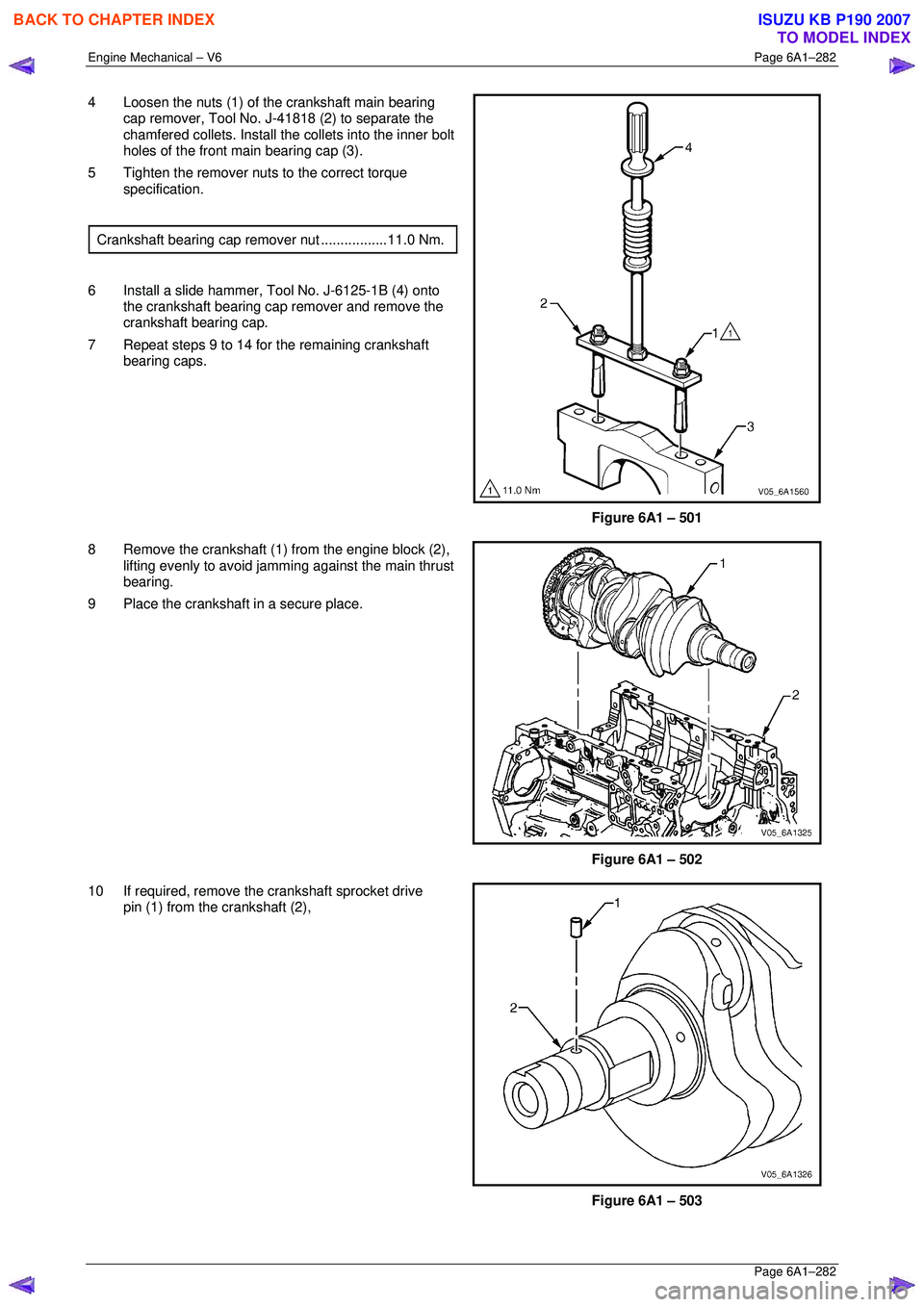
4 Loosen the nuts (1) of the crankshaft main bearing
cap remover, Tool No. J-41818 (2) to separate the
chamfered collets. Install the collets into the inner bolt
holes of the front main bearing cap (3).
5 Tighten the remover nuts to the correct torque specification.
Crankshaft bearing cap remover nut.................11.0 Nm.
6 Install a slide hammer, Tool No. J-6125-1B (4) onto the crankshaft bearing cap remover and remove the
crankshaft bearing cap.
7 Repeat steps 9 to 14 for the remaining crankshaft bearing caps.
Figure 6A1 – 501
8 Remove the crankshaft (1) from the engine block (2), lifting evenly to avoid jamming against the main thrust
bearing.
9 Place the crankshaft in a secure place.
Figure 6A1 – 502
10 If required, remove the crankshaft sprocket drive pin (1) from the crankshaft (2),
Figure 6A1 – 503
BACK TO CHAPTER INDEX
TO MODEL INDEX
ISUZU KB P190 2007
Page 3060 of 6020
Engine Mechanical – V6 Page 6A1–283
Page 6A1–283
Crankshaft Bearing
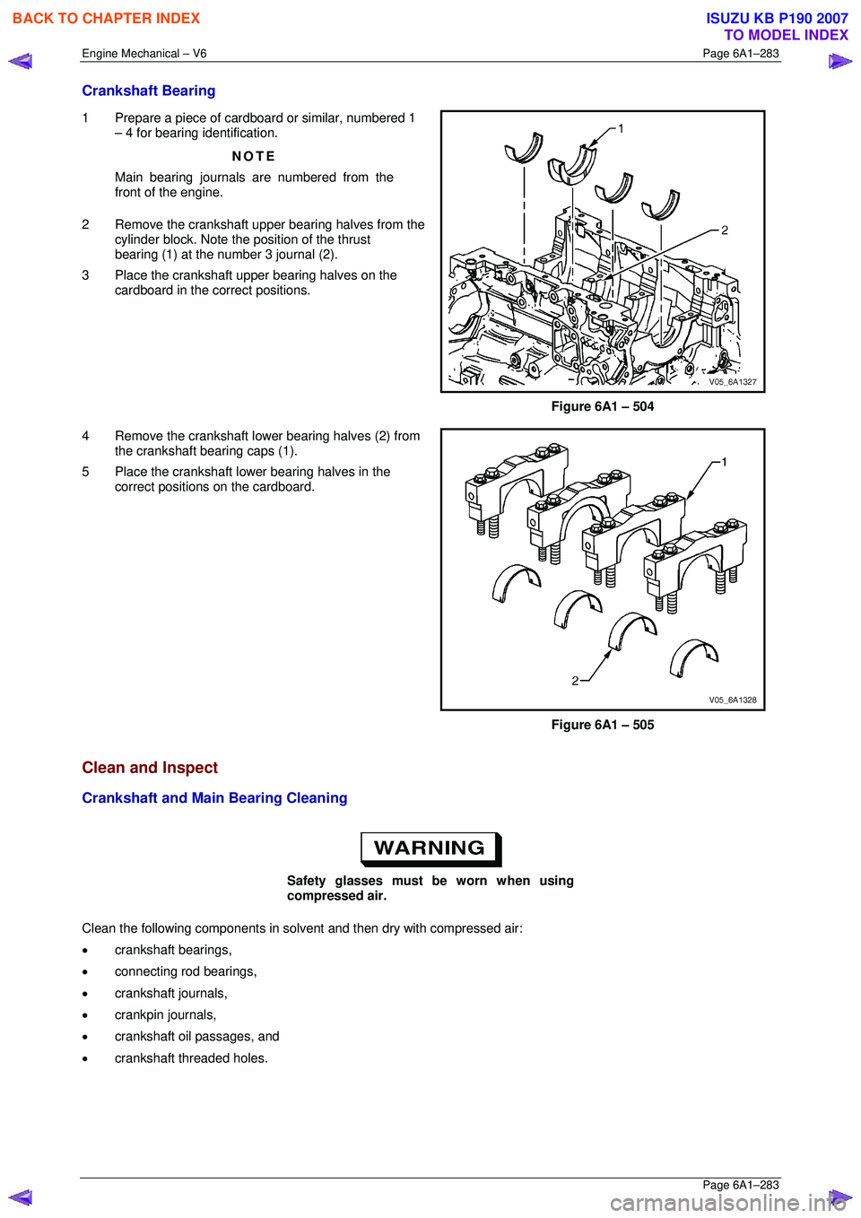
1 Prepare a piece of cardboard or similar, numbered 1
– 4 for bearing identification.
NOTE
Main bearing journals are numbered from the
front of the engine.
2 Remove the crankshaft upper bearing halves from the cylinder block. Note the position of the thrust
bearing (1) at the number 3 journal (2).
3 Place the crankshaft upper bearing halves on the cardboard in the correct positions.
Figure 6A1 – 504
4 Remove the crankshaft lower bearing halves (2) from the crankshaft bearing caps (1).
5 Place the crankshaft lower bearing halves in the correct positions on the cardboard.
Figure 6A1 – 505
Clean and Inspect
Crankshaft and Main Bearing Cleaning
Safety glasses must be worn when using
compressed air.
Clean the following components in solvent and then dry with compressed air:
• crankshaft bearings,
• connecting rod bearings,
• crankshaft journals,
• crankpin journals,
• crankshaft oil passages, and
• crankshaft threaded holes.
BACK TO CHAPTER INDEX
TO MODEL INDEX
ISUZU KB P190 2007
Page 3065 of 6020
Engine Mechanical – V6 Page 6A1–288
Page 6A1–288
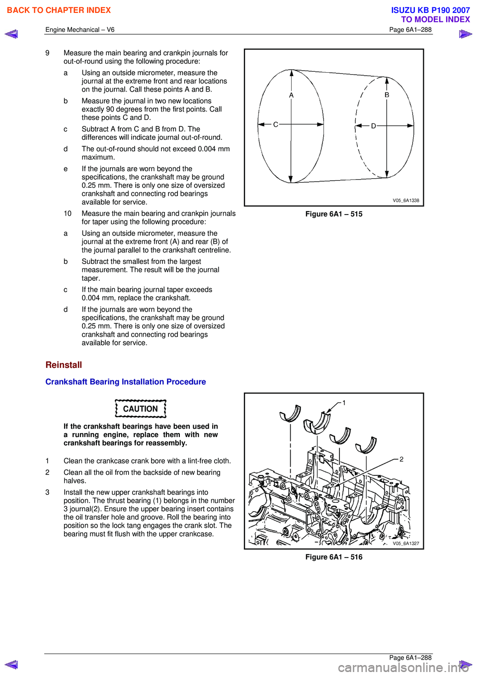
9 Measure the main bearing and crankpin journals for
out-of-round using the following procedure:
a Using an outside micr ometer, measure the
journal at the extreme front and rear locations
on the journal. Call these points A and B.
b Measure the journal in two new locations exactly 90 degrees from the first points. Call
these points C and D.
c Subtract A from C and B from D. The differences will indicate journal out-of-round.
d The out-of-round shoul d not exceed 0.004 mm
maximum.
e If the journals are worn beyond the specifications, the crankshaft may be ground
0.25 mm. There is only one size of oversized
crankshaft and connecting rod bearings
available for service.
10 Measure the main bearing and crankpin journals for taper using the following procedure:
a Using an outside micr ometer, measure the
journal at the extreme fr ont (A) and rear (B) of
the journal parallel to t he crankshaft centreline.
b Subtract the smallest from the largest measurement. The result will be the journal
taper.
c If the main bearing journal taper exceeds 0.004 mm, replace the crankshaft.
d If the journals are worn beyond the specifications, the crankshaft may be ground
0.25 mm. There is only one size of oversized
crankshaft and connecting rod bearings
available for service.
Figure 6A1 – 515
Reinstall
Crankshaft Bearing Installation Procedure
CAUTION
If the crankshaft bearings have been used in
a running engine, replace them with new
crankshaft bearings for reassembly.
1 Clean the crankcase crank bore with a lint-free cloth.
2 Clean all the oil from the backside of new bearing halves.
3 Install the new upper crankshaft bearings into position. The thrust beari ng (1) belongs in the number
3 journal(2). Ensure the upper bearing insert contains
the oil transfer hole and groove. Roll the bearing into
position so the lock tang engages the crank slot. The
bearing must fit flush with the upper crankcase.
Figure 6A1 – 516
BACK TO CHAPTER INDEX
TO MODEL INDEX
ISUZU KB P190 2007
Page 3067 of 6020
Engine Mechanical – V6 Page 6A1–290
Page 6A1–290
NOTE
Do not rotate the crankshaft.
9 Allow the assembly to sit for 2 minutes.
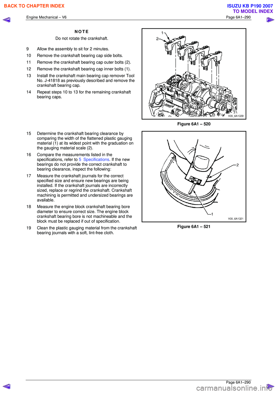
10 Remove the crankshaft bearing cap side bolts.
11 Remove the crankshaft bearing cap outer bolts (2).
12 Remove the crankshaft bearing cap inner bolts (1).
13 Install the crankshaft main bearing cap remover Tool No. J-41818 as previously described and remove the
crankshaft bearing cap.
14 Repeat steps 10 to 13 for the remaining crankshaft bearing caps.
Figure 6A1 – 520
15 Determine the crankshaft bearing clearance by comparing the width of the flattened plastic gauging
material (1) at its widest point with the graduation on
the gauging material scale (2).
16 Compare the measur ements listed in the
specifications, refer to 5 Specifications. If the new
bearings do not provide the correct crankshaft to
bearing clearance, inspect the following:
17 Measure the crankshaft journals for the correct specified size and ensure new bearings are being
installed. If the crankshaft journals are incorrectly
sized, replace or regrind the crankshaft. Crankshaft
machining is permitted and undersized bearings are
available.
18 Measure the engine block crankshaft bearing bore diameter to ensure correct size. The engine block
crankshaft bearing bore is not machineable and the
block must be replaced if out of specification.
19 Clean the plastic gauging material from the crankshaft bearing journals with a soft, lint-free cloth.
Figure 6A1 – 521
BACK TO CHAPTER INDEX
TO MODEL INDEX
ISUZU KB P190 2007