Page 2905 of 6020

Engine Mechanical – V6 Page 6A1–128
Page 6A1–128
2 Inspect the tensioner for locked or binding tensioner shaft (2). Reset the plunger (3) and ensure the tensioner shaft
moves freely in and out of the body of the tensioner.
NOTE
To reset the tensioner, use a suitably sized flat
blade screwdriver or Tool No. J 45027 (4) to wind
the plunger in a clockwise direction, into the
tensioner shaft.
3 Replace a damaged tens ioner as required.
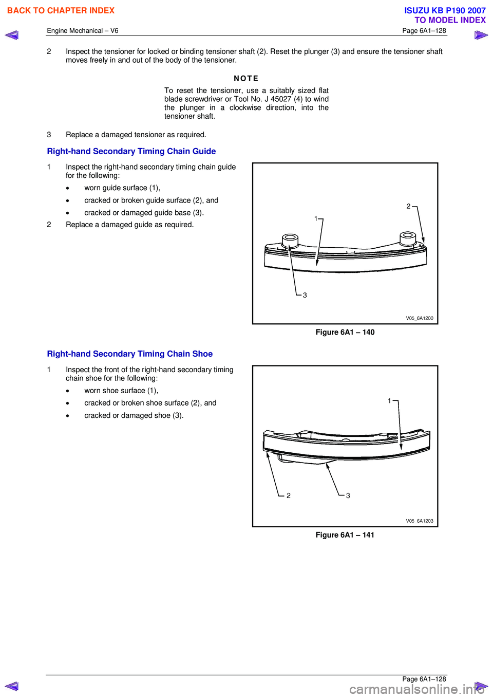
Right-hand Secondary Timing Chain Guide
1 Inspect the right-hand secondary timing chain guide
for the following:
• worn guide surface (1),
• cracked or broken guide surface (2), and
• cracked or damaged guide base (3).
2 Replace a damaged guide as required.
Figure 6A1 – 140
Right-hand Secondary Timing Chain Shoe
1 Inspect the front of t he right-hand secondary timing
chain shoe for the following:
• worn shoe surface (1),
• cracked or broken shoe surface (2), and
• cracked or damaged shoe (3).
Figure 6A1 – 141
BACK TO CHAPTER INDEX
TO MODEL INDEX
ISUZU KB P190 2007
Page 2906 of 6020
Engine Mechanical – V6 Page 6A1–129
Page 6A1–129
2 Inspect the back of the shoe for a damaged, worn or
missing timing chain tensioner contact pad (1).
Replace a damaged shoe as required.
Figure 6A1 – 142
Right-hand Secondary Timing Chain Tensioner
Figure 6A1 – 143
1 Inspect the right-hand secondary timing chain tensioner for damaged plunger-to-shoe contact surface (1), refer to
Figure 6A1 – 141.
NOTE
To reset the tensioner, use a suitably sized flat
blade screwdriver or Tool No. J 45027 (4) to wind
the plunger in a clockwise direction, into the
tensioner shaft.
2 Inspect the tensioner for a locked or binding tensioner shaft (2). Reset the plunger (3) and ensure the tensioner
shaft moves freely in and out of the body of the tensioner.
3 Replace a damaged tens ioner as required.
BACK TO CHAPTER INDEX
TO MODEL INDEX
ISUZU KB P190 2007
Page 2907 of 6020
Engine Mechanical – V6 Page 6A1–130
Page 6A1–130
Reinstall
Left-hand Secondary Timing Chain Components – Excluding MY06 Update
1 Install the crankshaft sprocket (1) onto the
crankshaft (2) by aligning the keyway to the key on
the crankshaft.
2 Slide the crankshaft sprocket on the crankshaft until the crankshaft sprocket contacts the step in the
crankshaft.
Figure 6A1 – 144
NOTE
Ensure that the crankshaft sprocket is installed
with the timing mark (1) visible.
Figure 6A1 – 145
CAUTION
In order to install Tool No. EN 46105 onto the
camshafts, rotate the camshafts in an anti-
clockwise direction. There should be no
need to rotate the camshaft more than 45
degrees.
Figure 6A1 – 146
BACK TO CHAPTER INDEX
TO MODEL INDEX
ISUZU KB P190 2007
Page 2908 of 6020
Engine Mechanical – V6 Page 6A1–131
Page 6A1–131
3 Install Tool No. EN 46105-1 (1) onto the rear of the
left-hand cylinder head camshafts (2), and Tool No.
EN 46105-2 onto the rear of the right-hand cylinder
head camshafts.
4 Ensure that Tool No. EN 46105 is fully seated onto the camshafts.
CAUTION
All camshafts must be locked in place before
installation of any timing chains.
Figure 6A1 – 147
5 Using Tool No. EN46111 (1), rotate the crankshaft in a clockwise direction until the crankshaft sprocket
timing mark (2) is aligned with the indexing mark (3)
on the oil pump housing.
Figure 6A1 – 148
6 Install the left-hand secondary timing chain (1) aligning the chain in the following manner:
Figure 6A1 – 149
BACK TO CHAPTER INDEX
TO MODEL INDEX
ISUZU KB P190 2007
Page 2911 of 6020
Engine Mechanical – V6 Page 6A1–134
Page 6A1–134
13 Install the left-hand camshaft intermediate sprocket to
the cylinder block.
14 Install the sprocket bolt (1) and tighten to the correct torque specification.
Camshaft intermediate sprocket
attaching bolt torque spec ification ........... 58.0 – 72.0 Nm
Figure 6A1 – 155
15 Verify the left-hand secondary timing chain timing mark alignments (1 to 6)
Figure 6A1 – 156
16 Ensure the left-hand secondary timing chain guide is selected and orientated correctly.
CAUTION
The left-hand secondary timing chain guide
is marked with the letters LH. Ensure the
correct shoe is used when installing to the
left-hand side in this procedure and that the
letters ‘LH” are facing the front of the vehicle
when installed.
Figure 6A1 – 157
BACK TO CHAPTER INDEX
TO MODEL INDEX
ISUZU KB P190 2007
Page 2913 of 6020
Engine Mechanical – V6 Page 6A1–136
Page 6A1–136
21 Install the left-hand secondary timing chain shoe
bolt (1) and tighten to the co rrect torque specification.
NOTE
Ensure secondary timing chain shoe is clear of
the left-hand secondary timing chain tensioner
mounting pad, before ti ghtening the attaching
bolt.
Secondary timing chain shoe attaching
bolt torque specificat ion .......................... 20.0 – 26.0 Nm
Figure 6A1 – 161
22 Ensure the left-hand secondary timing chain tensioner is selected and orientated correctly.
Figure 6A1 – 162
23 Reset the left-hand secondary timing chain tensioner.
NOTE
To reset the tensioner, use a suitably sized flat
blade screwdriver (1) or Tool No. J 45027 (4) to
wind the plunger in a clockwise direction, into
the tensioner shaft (2).
Figure 6A1 – 163
BACK TO CHAPTER INDEX
TO MODEL INDEX
ISUZU KB P190 2007
Page 2914 of 6020

Engine Mechanical – V6 Page 6A1–137
Page 6A1–137
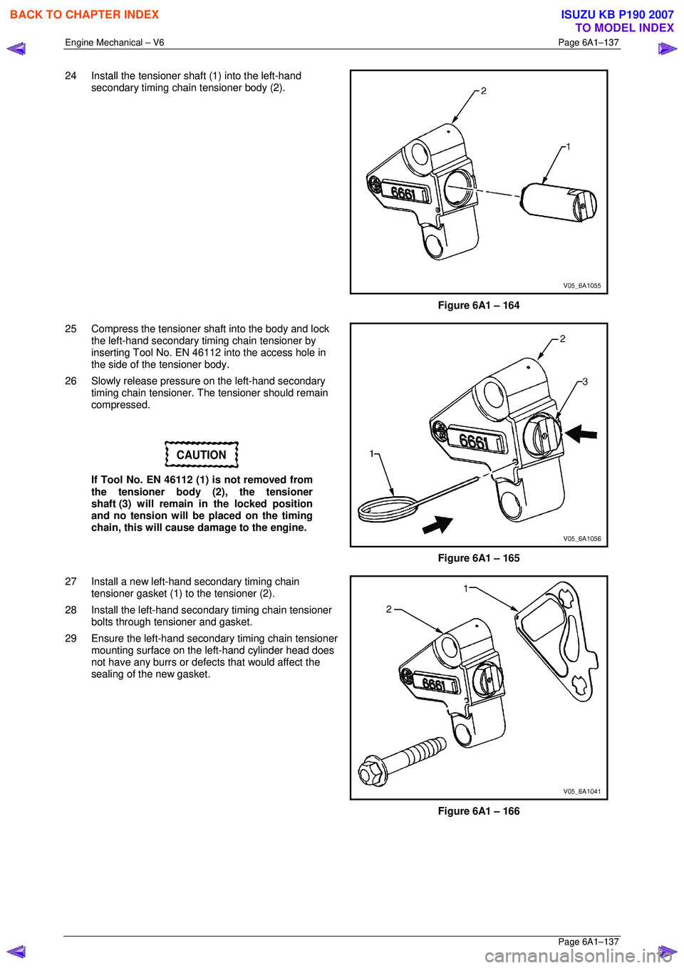
24 Install the tensioner shaft (1) into the left-hand
secondary timing chain tensioner body (2).
Figure 6A1 – 164
25 Compress the tensioner shaft into the body and lock the left-hand secondary timing chain tensioner by
inserting Tool No. EN 46112 into the access hole in
the side of the tensioner body.
26 Slowly release pressure on the left-hand secondary timing chain tensioner. The tensioner should remain
compressed.
CAUTION
If Tool No. EN 46112 (1) is not removed from
the tensioner body (2), the tensioner
shaft (3) will remain in the locked position
and no tension will be placed on the timing
chain, this will cause damage to the engine.
Figure 6A1 – 165
27 Install a new left-hand secondary timing chain tensioner gasket (1) to the tensioner (2).
28 Install the left-hand secondar y timing chain tensioner
bolts through tensioner and gasket.
29 Ensure the left-hand secondary timing chain tensioner mounting surface on the left-hand cylinder head does
not have any burrs or defects that would affect the
sealing of the new gasket.
Figure 6A1 – 166
BACK TO CHAPTER INDEX
TO MODEL INDEX
ISUZU KB P190 2007
Page 2915 of 6020
Engine Mechanical – V6 Page 6A1–138
Page 6A1–138
30 Place the left-hand secondary timing chain tensioner
(2) into position and loosely install the bolts (1) to the
cylinder head.
Figure 6A1 – 167
31 Verify the proper placement of the left-hand secondary timing chain tensioner gasket tab (1).
32 Tighten the left-hand secondary timing chain tensioner bolts (2) to the co rrect torque specification.
Secondary timing chain tensioner
attaching bolt torque spec ification ........... 20.0 – 26.0 Nm
Figure 6A1 – 168
33 Release the left-hand secondary timing chain tensioner (1) by pulling out Tools No. EN 46112 (2)
and unlocking the tensioner shaft.
Figure 6A1 – 169
BACK TO CHAPTER INDEX
TO MODEL INDEX
ISUZU KB P190 2007