2007 ISUZU KB P190 air condition
[x] Cancel search: air conditionPage 1819 of 6020
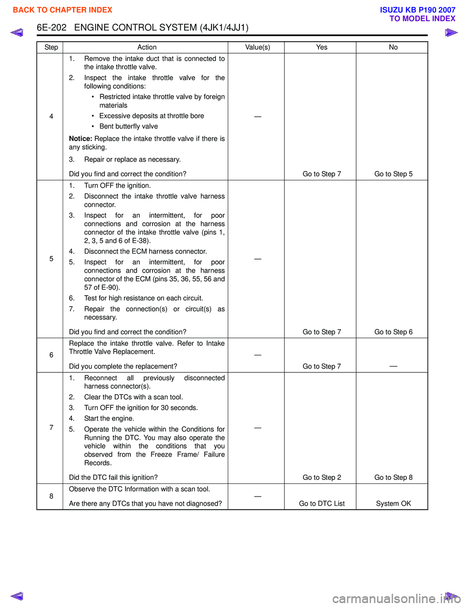
6E-202 ENGINE CONTROL SYSTEM (4JK1/4JJ1)
41. Remove the intake duct that is connected to
the intake throttle valve.
2. Inspect the intake throttle valve for the following conditions:
• Restricted intake throttle valve by foreign materials
• Excessive deposits at throttle bore
• Bent butterfly valve
Notice: Replace the intake throttle valve if there is
any sticking.
3. Repair or replace as necessary.
Did you find and correct the condition? —
Go to Step 7 Go to Step 5
5 1. Turn OFF the ignition.
2. Disconnect the intake throttle valve harness connector.
3. Inspect for an intermittent, for poor connections and corrosion at the harness
connector of the intake throttle valve (pins 1,
2, 3, 5 and 6 of E-38).
4. Disconnect the ECM harness connector.
5. Inspect for an intermittent, for poor connections and corrosion at the harness
connector of the ECM (pins 35, 36, 55, 56 and
57 of E-90).
6. Test for high resistance on each circuit.
7. Repair the connection(s) or circuit(s) as necessary.
Did you find and correct the condition? —
Go to Step 7 Go to Step 6
6 Replace the intake throttle valve. Refer to Intake
Throttle Valve Replacement.
Did you complete the replacement? —
Go to Step 7
—
71. Reconnect all previously disconnected
harness connector(s).
2. Clear the DTCs with a scan tool.
3. Turn OFF the ignition for 30 seconds.
4. Start the engine.
5. Operate the vehicle within the Conditions for Running the DTC. You may also operate the
vehicle within the conditions that you
observed from the Freeze Frame/ Failure
Records.
Did the DTC fail this ignition? —
Go to Step 2 Go to Step 8
8 Observe the DTC Information with a scan tool.
Are there any DTCs that you have not diagnosed? —
Go to DTC List System OK
Step
Action Value(s)Yes No
BACK TO CHAPTER INDEX
TO MODEL INDEX
ISUZU KB P190 2007
Page 1820 of 6020
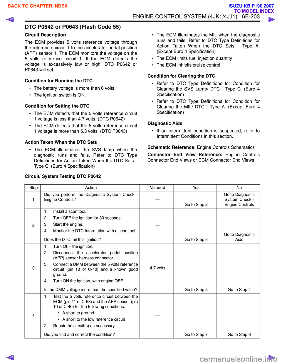
ENGINE CONTROL SYSTEM (4JK1/4JJ1) 6E-203
DTC P0642 or P0643 (Flash Code 55)
Circuit Description
The ECM provides 5 volts reference voltage through
the reference circuit 1 to the accelerator pedal position
(APP) sensor 1. The ECM monitors the voltage on the
5 volts reference circuit 1. If the ECM detects the
voltage is excessively low or high, DTC P0642 or
P0643 will set.
Condition for Running the DTC • The battery voltage is more than 6 volts.
• The ignition switch is ON.
Condition for Setting the DTC • The ECM detects that the 5 volts reference circuit 1 voltage is less than 4.7 volts. (DTC P0642)
• The ECM detects that the 5 volts reference circuit 1 voltage is more than 5.3 volts. (DTC P0643)
Action Taken When the DTC Sets • The ECM illuminates the SVS lamp when the diagnostic runs and fails. Refer to DTC Type
Definitions for Action Taken When the DTC Sets -
Type C. (Euro 4 Specification) • The ECM illuminates the MIL when the diagnostic
runs and fails. Refer to DTC Type Definitions for
Action Taken When the DTC Sets - Type A.
(Except Euro 4 Specification)
• The ECM limits fuel injection quantity
• The ECM inhibits cruise control.
Condition for Clearing the DTC • Refer to DTC Type Definitions for Condition for Clearing the SVS Lamp/ DTC - Type C. (Euro 4
Specification)
• Refer to DTC Type Definitions for Condition for Clearing the MIL/ DTC - Type A. (Except Euro 4
Specification)
Diagnostic Aids • If an intermittent condition is suspected, refer to Intermittent Conditions in this section.
Schematic Reference: Engine Controls Schematics
Connector End View Reference: Engine Controls
Connector End Views or ECM Connector End Views
Circuit/ System Testing DTC P0642
Step Action Value(s)Yes No
1 Did you perform the Diagnostic System Check -
Engine Controls? —
Go to Step 2 Go to Diagnostic
System Check -
Engine Controls
2 1. Install a scan tool.
2. Turn OFF the ignition for 30 seconds.
3. Start the engine.
4. Monitor the DTC Information with a scan tool.
Does the DTC fail this ignition? —
Go to Step 3 Go to Diagnostic
Aids
3 1. Turn OFF the ignition.
2. Disconnect the accelerator pedal position (APP) sensor harness connector.
3. Connect a DMM between the 5 volts reference circuit (pin 10 of C-40) and a known good
ground.
4. Turn ON the ignition, with engine OFF.
Is the DMM voltage more than the specified value? 4.7 volts
Go to Step 5 Go to Step 4
4 1. Test the 5 volts reference circuit between the
ECM (pin 11 of C-58) and the APP sensor (pin
10 of C-40) for the following conditions:
• A short to ground
• A short to the low reference circuit
2. Repair the circuit(s) as necessary.
Did you find and correct the condition? —
Go to Step 7 Go to Step 6
BACK TO CHAPTER INDEX
TO MODEL INDEX
ISUZU KB P190 2007
Page 1821 of 6020
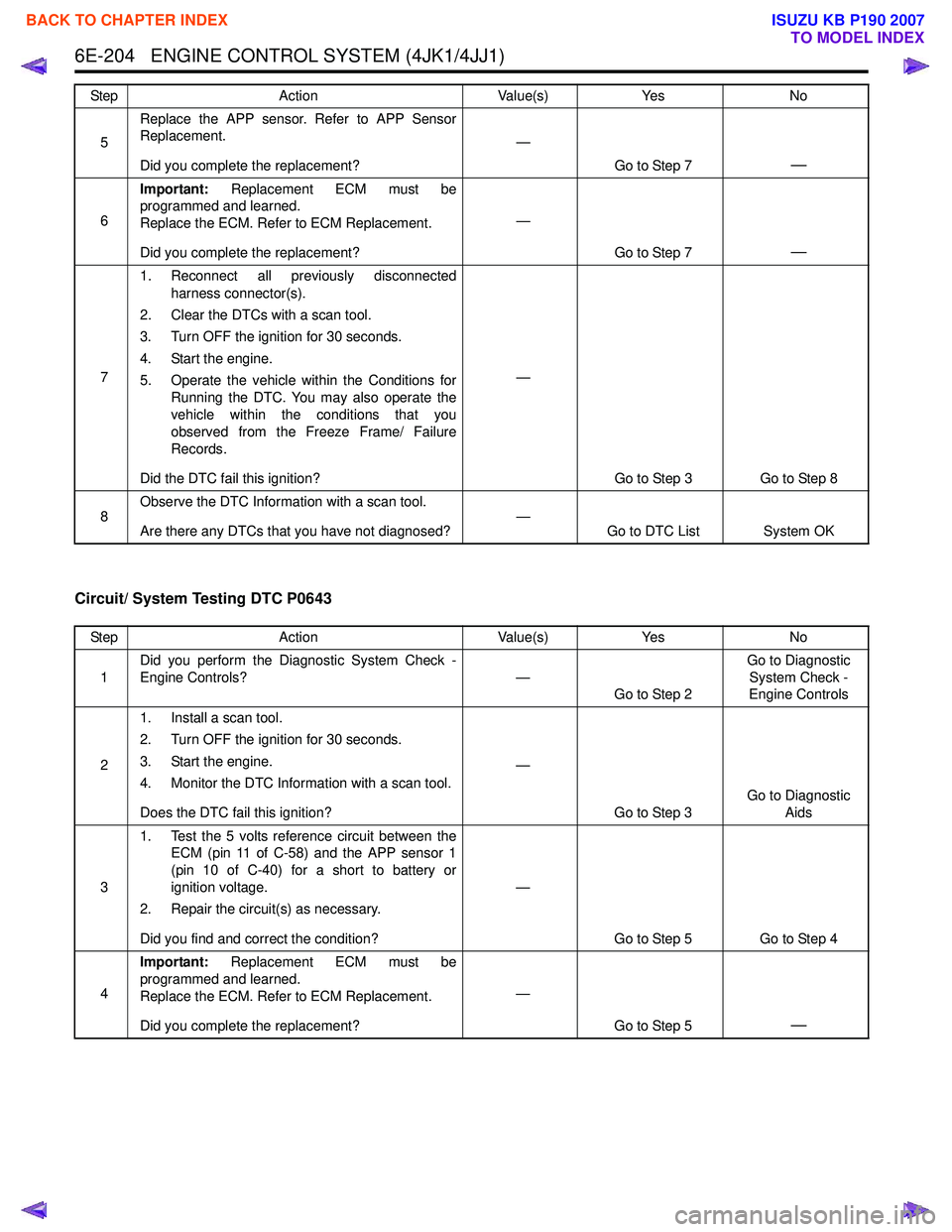
6E-204 ENGINE CONTROL SYSTEM (4JK1/4JJ1)
Circuit/ System Testing DTC P0643
5Replace the APP sensor. Refer to APP Sensor
Replacement.
Did you complete the replacement? —
Go to Step 7
—
6Important:
Replacement ECM must be
programmed and learned.
Replace the ECM. Refer to ECM Replacement.
Did you complete the replacement? —
Go to Step 7
—
71. Reconnect all previously disconnected
harness connector(s).
2. Clear the DTCs with a scan tool.
3. Turn OFF the ignition for 30 seconds.
4. Start the engine.
5. Operate the vehicle within the Conditions for Running the DTC. You may also operate the
vehicle within the conditions that you
observed from the Freeze Frame/ Failure
Records.
Did the DTC fail this ignition? —
Go to Step 3 Go to Step 8
8 Observe the DTC Information with a scan tool.
Are there any DTCs that you have not diagnosed? —
Go to DTC List System OK
Step
Action Value(s)Yes No
Step Action Value(s)Yes No
1 Did you perform the Diagnostic System Check -
Engine Controls? —
Go to Step 2 Go to Diagnostic
System Check -
Engine Controls
2 1. Install a scan tool.
2. Turn OFF the ignition for 30 seconds.
3. Start the engine.
4. Monitor the DTC Information with a scan tool.
Does the DTC fail this ignition? —
Go to Step 3 Go to Diagnostic
Aids
3 1. Test the 5 volts reference circuit between the
ECM (pin 11 of C-58) and the APP sensor 1
(pin 10 of C-40) for a short to battery or
ignition voltage.
2. Repair the circuit(s) as necessary.
Did you find and correct the condition? —
Go to Step 5 Go to Step 4
4 Important:
Replacement ECM must be
programmed and learned.
Replace the ECM. Refer to ECM Replacement.
Did you complete the replacement? —
Go to Step 5
—
BACK TO CHAPTER INDEX
TO MODEL INDEX
ISUZU KB P190 2007
Page 1823 of 6020
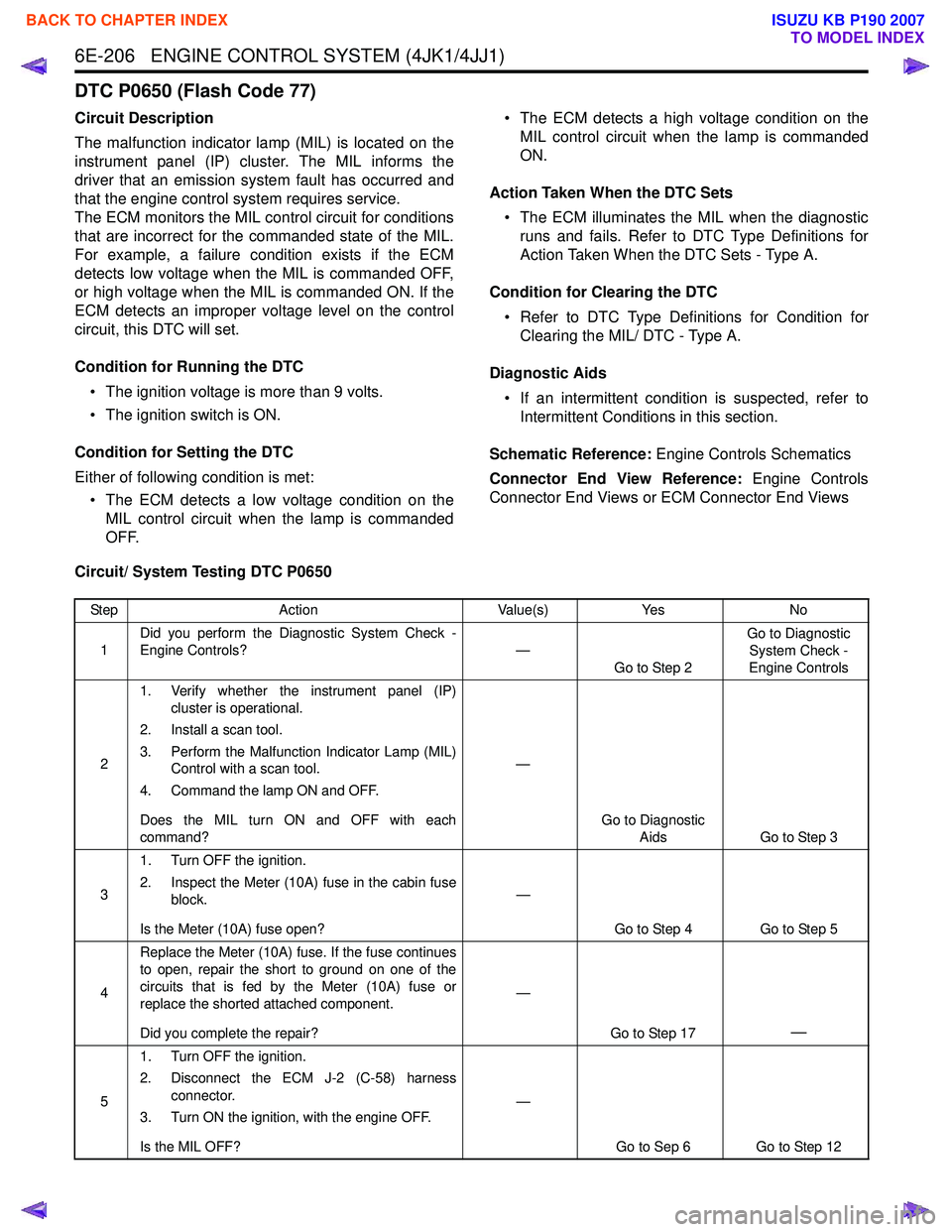
6E-206 ENGINE CONTROL SYSTEM (4JK1/4JJ1)
DTC P0650 (Flash Code 77)
Circuit Description
The malfunction indicator lamp (MIL) is located on the
instrument panel (IP) cluster. The MIL informs the
driver that an emission system fault has occurred and
that the engine control system requires service.
The ECM monitors the MIL control circuit for conditions
that are incorrect for the commanded state of the MIL.
For example, a failure condition exists if the ECM
detects low voltage when the MIL is commanded OFF,
or high voltage when the MIL is commanded ON. If the
ECM detects an improper voltage level on the control
circuit, this DTC will set.
Condition for Running the DTC • The ignition voltage is more than 9 volts.
• The ignition switch is ON.
Condition for Setting the DTC
Either of following condition is met: • The ECM detects a low voltage condition on the MIL control circuit when the lamp is commanded
OFF. • The ECM detects a high voltage condition on the
MIL control circuit when the lamp is commanded
ON.
Action Taken When the DTC Sets • The ECM illuminates the MIL when the diagnostic runs and fails. Refer to DTC Type Definitions for
Action Taken When the DTC Sets - Type A.
Condition for Clearing the DTC • Refer to DTC Type Definitions for Condition for Clearing the MIL/ DTC - Type A.
Diagnostic Aids • If an intermittent condition is suspected, refer to Intermittent Conditions in this section.
Schematic Reference: Engine Controls Schematics
Connector End View Reference: Engine Controls
Connector End Views or ECM Connector End Views
Circuit/ System Testing DTC P0650
Step Action Value(s)Yes No
1 Did you perform the Diagnostic System Check -
Engine Controls? —
Go to Step 2 Go to Diagnostic
System Check -
Engine Controls
2 1. Verify whether the instrument panel (IP)
cluster is operational.
2. Install a scan tool.
3. Perform the Malfunction Indicator Lamp (MIL) Control with a scan tool.
4. Command the lamp ON and OFF.
Does the MIL turn ON and OFF with each
command? —
Go to Diagnostic Aids Go to Step 3
3 1. Turn OFF the ignition.
2. Inspect the Meter (10A) fuse in the cabin fuse block.
Is the Meter (10A) fuse open? —
Go to Step 4 Go to Step 5
4 Replace the Meter (10A) fuse. If the fuse continues
to open, repair the short to ground on one of the
circuits that is fed by the Meter (10A) fuse or
replace the shorted attached component.
Did you complete the repair? —
Go to Step 17
—
51. Turn OFF the ignition.
2. Disconnect the ECM J-2 (C-58) harness connector.
3. Turn ON the ignition, with the engine OFF.
Is the MIL OFF? —
Go to Sep 6 Go to Step 12
BACK TO CHAPTER INDEX
TO MODEL INDEX
ISUZU KB P190 2007
Page 1824 of 6020
ENGINE CONTROL SYSTEM (4JK1/4JJ1) 6E-207
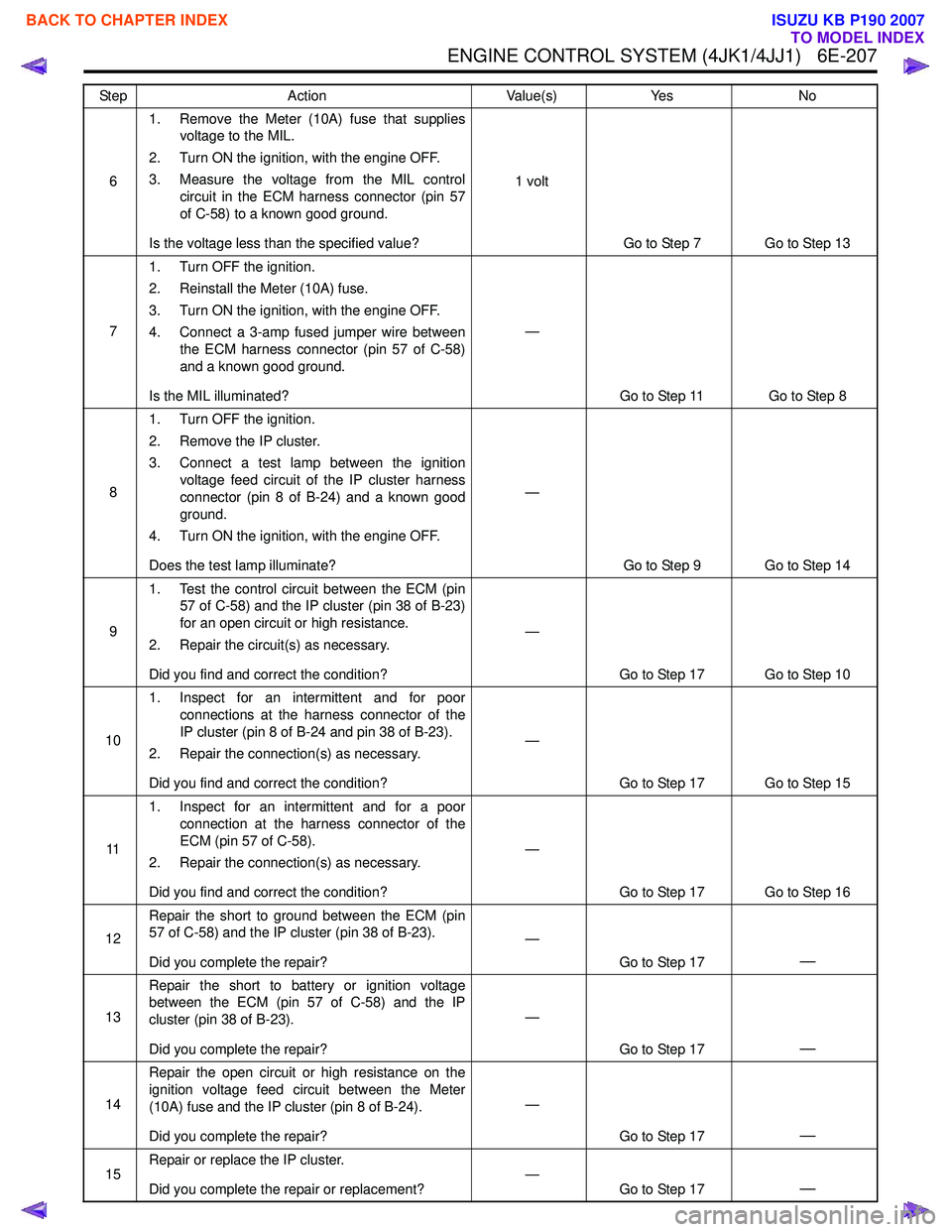
61. Remove the Meter (10A) fuse that supplies
voltage to the MIL.
2. Turn ON the ignition, with the engine OFF.
3. Measure the voltage from the MIL control circuit in the ECM harness connector (pin 57
of C-58) to a known good ground.
Is the voltage less than the specified value? 1 volt
Go to Step 7 Go to Step 13
7 1. Turn OFF the ignition.
2. Reinstall the Meter (10A) fuse.
3. Turn ON the ignition, with the engine OFF.
4. Connect a 3-amp fused jumper wire between the ECM harness connector (pin 57 of C-58)
and a known good ground.
Is the MIL illuminated? —
Go to Step 11 Go to Step 8
8 1. Turn OFF the ignition.
2. Remove the IP cluster.
3. Connect a test lamp between the ignition voltage feed circuit of the IP cluster harness
connector (pin 8 of B-24) and a known good
ground.
4. Turn ON the ignition, with the engine OFF.
Does the test lamp illuminate? —
Go to Step 9 Go to Step 14
9 1. Test the control circuit between the ECM (pin
57 of C-58) and the IP cluster (pin 38 of B-23)
for an open circuit or high resistance.
2. Repair the circuit(s) as necessary.
Did you find and correct the condition? —
Go to Step 17 Go to Step 10
10 1. Inspect for an intermittent and for poor
connections at the harness connector of the
IP cluster (pin 8 of B-24 and pin 38 of B-23).
2. Repair the connection(s) as necessary.
Did you find and correct the condition? —
Go to Step 17 Go to Step 15
11 1. Inspect for an intermittent and for a poor
connection at the harness connector of the
ECM (pin 57 of C-58).
2. Repair the connection(s) as necessary.
Did you find and correct the condition? —
Go to Step 17 Go to Step 16
12 Repair the short to ground between the ECM (pin
57 of C-58) and the IP cluster (pin 38 of B-23).
Did you complete the repair? —
Go to Step 17
—
13Repair the short to battery or ignition voltage
between the ECM (pin 57 of C-58) and the IP
cluster (pin 38 of B-23).
Did you complete the repair? —
Go to Step 17
—
14Repair the open circuit or high resistance on the
ignition voltage feed circuit between the Meter
(10A) fuse and the IP cluster (pin 8 of B-24).
Did you complete the repair? —
Go to Step 17
—
15Repair or replace the IP cluster.
Did you complete the repair or replacement? —
Go to Step 17—
Step Action Value(s)Yes No
BACK TO CHAPTER INDEX
TO MODEL INDEX
ISUZU KB P190 2007
Page 1827 of 6020

6E-210 ENGINE CONTROL SYSTEM (4JK1/4JJ1)
41. Leave the DMM connected to the BARO
sensor harness connector.
2. Turn OFF the ignition.
3. Disconnect the EGR valve harness connector.
4. Turn ON the ignition, with the engine OFF.
Does the DMM voltage change to more than the
specified value? 4.7 volts
Go to Step 10 Go to Step 5
5 1. Leave the DMM connected to the BARO
sensor harness connector.
2. Turn OFF the ignition.
3. Disconnect the fuel rail pressure (FRP) sensor harness connector.
4. Turn ON the ignition, with the engine OFF.
Does the DMM voltage change to more than the
specified value? 4.7 volts
Go to Step 11 Go to Step 6
6 1. Leave the DMM connected to the BARO
sensor harness connector.
2. Turn OFF the ignition.
3. Disconnect the camshaft position (CMP) sensor harness connector.
4. Turn ON the ignition, with the engine OFF.
Does the DMM voltage change to more than the
specified value? 4.7 volts
Go to Step 12 Go to Step 7
7 1. Leave the DMM connected to the BARO
sensor harness connector.
2. Turn OFF the ignition.
3. Disconnect the accelerator pedal position (APP) sensor harness connector.
4. Turn ON the ignition, with the engine OFF.
Does the DMM voltage change to more than the
specified value? 4.7 volts
Go to Step 13 Go to Step 8
8 1. Test the 5 volts reference circuit between the
ECM and the following components for a short
to ground or short to the low reference circuit:
• ECM (pin 19 of E-90) and BARO sensor (pin 3 of E-40)
• ECM (pin 31 of E-90) and EGR position sensor (pin 1 of E-71)
• ECM (pin 47 of E-90) and FRP sensor (pin 3 of E-48)
• ECM (pin 46 of E-90) and CMP sensor (pin 3 of E-39)
• ECM (pin 9 of C-58) and APP sensor 2 (pin 8 of C-40)
2. Repair the circuit(s) as necessary.
Did you find and correct the condition? —
Go to Step 15 Go to Step 14
9 Replace the BARO sensor. Refer to BARO Sensor
Replacement.
Did you complete the replacement? —
Go to Step 15
—
10Replace the EGR valve. Refer to EGR Valve
Replacement.
Did you complete the replacement? —
Go to Step 15
—
Step Action Value(s)Yes No
BACK TO CHAPTER INDEX
TO MODEL INDEX
ISUZU KB P190 2007
Page 1829 of 6020
6E-212 ENGINE CONTROL SYSTEM (4JK1/4JJ1)
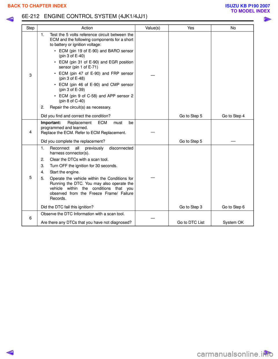
31. Test the 5 volts reference circuit between the
ECM and the following components for a short
to battery or ignition voltage:
• ECM (pin 19 of E-90) and BARO sensor (pin 3 of E-40)
• ECM (pin 31 of E-90) and EGR position sensor (pin 1 of E-71)
• ECM (pin 47 of E-90) and FRP sensor (pin 3 of E-48)
• ECM (pin 46 of E-90) and CMP sensor (pin 3 of E-39)
• ECM (pin 9 of C-58) and APP sensor 2 (pin 8 of C-40)
2. Repair the circuit(s) as necessary.
Did you find and correct the condition? —
Go to Step 5 Go to Step 4
4 Important:
Replacement ECM must be
programmed and learned.
Replace the ECM. Refer to ECM Replacement.
Did you complete the replacement? —
Go to Step 5
—
51. Reconnect all previously disconnected
harness connector(s).
2. Clear the DTCs with a scan tool.
3. Turn OFF the ignition for 30 seconds.
4. Start the engine.
5. Operate the vehicle within the Conditions for Running the DTC. You may also operate the
vehicle within the conditions that you
observed from the Freeze Frame/ Failure
Records.
Did the DTC fail this ignition? —
Go to Step 3 Go to Step 6
6 Observe the DTC Information with a scan tool.
Are there any DTCs that you have not diagnosed? —
Go to DTC List System OK
Step
Action Value(s)Yes No
BACK TO CHAPTER INDEX
TO MODEL INDEX
ISUZU KB P190 2007
Page 1831 of 6020
6E-214 ENGINE CONTROL SYSTEM (4JK1/4JJ1)
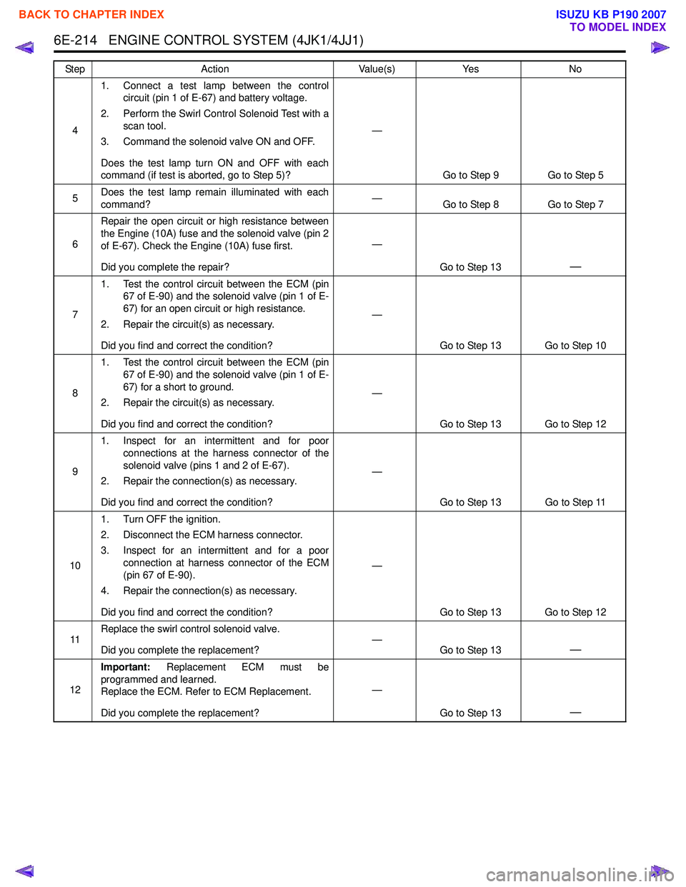
41. Connect a test lamp between the control
circuit (pin 1 of E-67) and battery voltage.
2. Perform the Swirl Control Solenoid Test with a scan tool.
3. Command the solenoid valve ON and OFF.
Does the test lamp turn ON and OFF with each
command (if test is aborted, go to Step 5)? —
Go to Step 9 Go to Step 5
5 Does the test lamp remain illuminated with each
command? —
Go to Step 8 Go to Step 7
6 Repair the open circuit or high resistance between
the Engine (10A) fuse and the solenoid valve (pin 2
of E-67). Check the Engine (10A) fuse first.
Did you complete the repair? —
Go to Step 13
—
71. Test the control circuit between the ECM (pin
67 of E-90) and the solenoid valve (pin 1 of E-
67) for an open circuit or high resistance.
2. Repair the circuit(s) as necessary.
Did you find and correct the condition? —
Go to Step 13 Go to Step 10
8 1. Test the control circuit between the ECM (pin
67 of E-90) and the solenoid valve (pin 1 of E-
67) for a short to ground.
2. Repair the circuit(s) as necessary.
Did you find and correct the condition? —
Go to Step 13 Go to Step 12
9 1. Inspect for an intermittent and for poor
connections at the harness connector of the
solenoid valve (pins 1 and 2 of E-67).
2. Repair the connection(s) as necessary.
Did you find and correct the condition? —
Go to Step 13 Go to Step 11
10 1. Turn OFF the ignition.
2. Disconnect the ECM harness connector.
3. Inspect for an intermittent and for a poor connection at harness connector of the ECM
(pin 67 of E-90).
4. Repair the connection(s) as necessary.
Did you find and correct the condition? —
Go to Step 13 Go to Step 12
11 Replace the swirl control solenoid valve.
Did you complete the replacement? —
Go to Step 13
—
12Important:
Replacement ECM must be
programmed and learned.
Replace the ECM. Refer to ECM Replacement.
Did you complete the replacement? —
Go to Step 13
—
Step Action Value(s)Yes No
BACK TO CHAPTER INDEX
TO MODEL INDEX
ISUZU KB P190 2007