2007 ISUZU KB P190 air condition
[x] Cancel search: air conditionPage 1861 of 6020
6E-244 ENGINE CONTROL SYSTEM (4JK1/4JJ1)
DTC P1262 (Flash Code 34)
Circuit Description
The charge up circuit in the ECM steps up the voltage
for fuel injectors and is divided into two banks, common
1 and common 2. The common 1 covers fuel injectors
in cylinders #1 and #4, and the common 2 covers fuel
injectors in cylinders #2 and #3. If the common 2 fuel
injector charge up circuit in the ECM is an insufficient
charge or an overcharge, this DTC will set.
Condition for Running the DTC • The battery voltage is more than 9 volts.
• The ignition switch is ON.
• The engine is not running.
Condition for Setting the DTC • The ECM detects that the common 2 fuel injector charge up circuit is an insufficient charge or an
overcharge. Action Taken When the DTC Sets
• The ECM illuminates the MIL when the diagnostic runs and fails. Refer to DTC Type Definitions for
Action Taken When the DTC Sets - Type A.
• The ECM limits fuel injection quantity.
• The ECM inhibits cruise control.
Condition for Clearing the DTC • Refer to DTC Type Definitions for Condition for Clearing the MIL/ DTC - Type A.
Diagnostic Aids • If an intermittent condition is suspected, refer to Intermittent Conditions in this section.
Schematic Reference: Engine Controls Schematics
Connector End View Reference: Engine Controls
Connector End Views or ECM Connector End Views
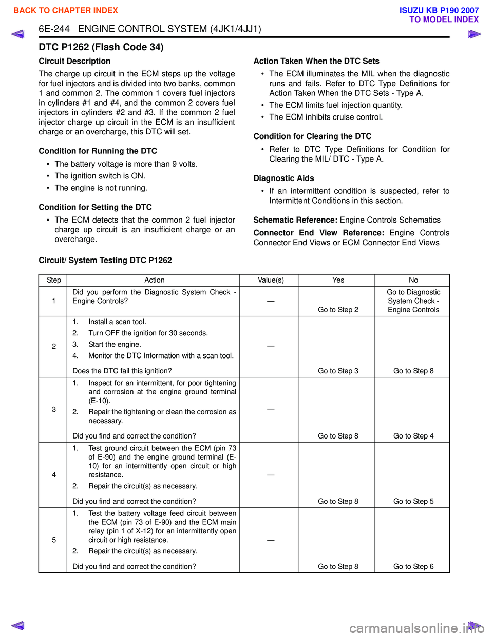
Circuit/ System Testing DTC P1262
Step Action Value(s)Yes No
1 Did you perform the Diagnostic System Check -
Engine Controls? —
Go to Step 2 Go to Diagnostic
System Check -
Engine Controls
2 1. Install a scan tool.
2. Turn OFF the ignition for 30 seconds.
3. Start the engine.
4. Monitor the DTC Information with a scan tool.
Does the DTC fail this ignition? —
Go to Step 3 Go to Step 8
3 1. Inspect for an intermittent, for poor tightening
and corrosion at the engine ground terminal
(E-10).
2. Repair the tightening or clean the corrosion as necessary.
Did you find and correct the condition? —
Go to Step 8 Go to Step 4
4 1. Test ground circuit between the ECM (pin 73
of E-90) and the engine ground terminal (E-
10) for an intermittently open circuit or high
resistance.
2. Repair the circuit(s) as necessary.
Did you find and correct the condition? —
Go to Step 8 Go to Step 5
5 1. Test the battery voltage feed circuit between
the ECM (pin 73 of E-90) and the ECM main
relay (pin 1 of X-12) for an intermittently open
circuit or high resistance.
2. Repair the circuit(s) as necessary.
Did you find and correct the condition? —
Go to Step 8 Go to Step 6
BACK TO CHAPTER INDEX
TO MODEL INDEX
ISUZU KB P190 2007
Page 1862 of 6020
ENGINE CONTROL SYSTEM (4JK1/4JJ1) 6E-245
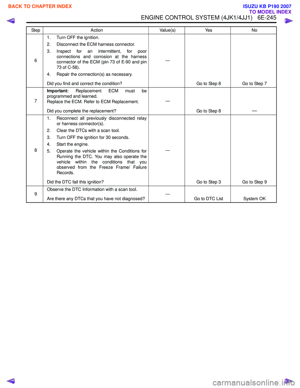
61. Turn OFF the ignition.
2. Disconnect the ECM harness connector.
3. Inspect for an intermittent, for poor connections and corrosion at the harness
connector of the ECM (pin 73 of E-90 and pin
73 of C-58).
4. Repair the connection(s) as necessary.
Did you find and correct the condition? —
Go to Step 8 Go to Step 7
7 Important:
Replacement ECM must be
programmed and learned.
Replace the ECM. Refer to ECM Replacement.
Did you complete the replacement? —
Go to Step 8
—
81. Reconnect all previously disconnected relay
or harness connector(s).
2. Clear the DTCs with a scan tool.
3. Turn OFF the ignition for 30 seconds.
4. Start the engine.
5. Operate the vehicle within the Conditions for Running the DTC. You may also operate the
vehicle within the conditions that you
observed from the Freeze Frame/ Failure
Records.
Did the DTC fail this ignition? —
Go to Step 3 Go to Step 9
9 Observe the DTC Information with a scan tool.
Are there any DTCs that you have not diagnosed? —
Go to DTC List System OK
Step
Action Value(s)Yes No
BACK TO CHAPTER INDEX
TO MODEL INDEX
ISUZU KB P190 2007
Page 1863 of 6020
6E-246 ENGINE CONTROL SYSTEM (4JK1/4JJ1)
DTC P1404 (Flash Code 45)
Circuit Description
The ECM controls the EGR valve opening based on the
engine running condition and by controlling the EGR
solenoid. The EGR valve position is detected by the
position sensor, and relayed to the ECM.
If the ECM detects that the actual EGR position is
higher than certain amount, this DTC will set. (Closed
Position Error DTC)
If the ECM detects a variance between the learned
closed position and actual closed position, this DTC will
also set. (Learned Position Error DTC)
Condition for Running the DTC
Closed Position Error DTC • DTCs P0112, P0113, P0116, P0117, P0118, P0404 P0405, P0406, P0652, P0653, P2227,
P2228 and P2229 are not set.
• The battery voltage is between 10 to 16 volts.
• The ignition switch is ON.
• The engine coolant temperature is between 20 to 11 0 °C (68 to 230 °F).
• The intake air temperature is between 0 to 110 °C
(32 to 230 °F).
• The barometric pressure is between 60 to 120 kPa (8.7 to 17.4 psi)
Learned Position Error DTC
• DTCs P0404, P0405 and P0406 are not set.
Condition for Setting the DTC
Closed Position Error DTC • The ECM detects that the actual EGR position is
more than 20% for 5 seconds when the EGR
control is commanded OFF.
Learned Position Error DTC
• The ECM detects that the EGR learned minimum position is more than 10% or less than -10% when
the ignition switch is OFF.
Action Taken When the DTC Sets • The ECM illuminates the MIL when the diagnostic runs and fails. Refer to DTC Type Definitions for
Action Taken When the DTC Sets - Type A.
• The ECM limits fuel injection quantity.
• The ECM inhibits pilot injection.
• The ECM inhibits EGR control. (Closed Position Error DTC)
• The ECM inhibits cruise control.
Condition for Clearing the DTC • Refer to DTC Type Definitions for Condition for Clearing the MIL/ DTC - Type A.
Diagnostic Aids • If an intermittent condition is suspected, refer to Intermittent Conditions in this section.
• A sticking or intermittently sticking EGR valve may set this DTC.
Schematic Reference: Engine Controls Schematics
Connector End View Reference: Engine Controls
Connector End Views or ECM Connector End Views
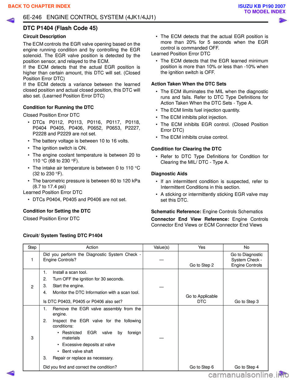
Circuit/ System Testing DTC P1404
Step Action Value(s)Yes No
1 Did you perform the Diagnostic System Check -
Engine Controls? —
Go to Step 2 Go to Diagnostic
System Check -
Engine Controls
2 1. Install a scan tool.
2. Turn OFF the ignition for 30 seconds.
3. Start the engine.
4. Monitor the DTC Information with a scan tool.
Is DTC P0403, P0405 or P0406 also set? —
Go to Applicable DTC Go to Step 3
3 1. Remove the EGR valve assembly from the
engine.
2. Inspect the EGR valve for the following conditions:
• Restricted EGR valve by foreign materials
• Excessive deposits at valve
• Bent valve shaft
3. Repair or replace as necessary.
Did you find and correct the condition? —
Go to Step 6 Go to Step 4
BACK TO CHAPTER INDEX
TO MODEL INDEX
ISUZU KB P190 2007
Page 1864 of 6020

ENGINE CONTROL SYSTEM (4JK1/4JJ1) 6E-247
41. Turn OFF the ignition.
2. Disconnect the EGR valve harness connector.
3. Inspect for an intermittent, for poor connections and corrosion at the harness
connector of the EGR valve (pins 1, 2, 3, 4
and 6 of E-71).
4. Disconnect the ECM harness connector.
5. Inspect for an intermittent, for poor connections and corrosion at the harness
connector of the ECM (pins 30, 31, 32, 62 and
63 of E-90).
6. Test for high resistance on each circuit.
7. Repair the connection(s) or circuit(s) as necessary.
Did you find and correct the condition? —
Go to Step 6 Go to Step 5
5 Replace the EGR valve. Refer to EGR Valve
Replacement.
Did you complete the replacement? —
Go to Step 6
—
61. Reconnect all previously disconnected
harness connector(s).
Notice: Ignition switch must be cycled before clear
the DTC.
2. Turn ON the ignition, with the engine OFF.
3. Turn OFF the ignition for 30 seconds.
4. Turn ON the ignition and clear the DTCs with a scan tool.
5. Turn OFF the ignition for 30 seconds.
6. Start the engine.
7. Operate the vehicle within the Conditions for Running the DTC. You may also operate the
vehicle within the conditions that you
observed from the Freeze Frame/ Failure
Records.
Did the DTC fail this ignition? —
Go to Step 2 Go to Step 7
7 Observe the DTC Information with a scan tool.
Are there any DTCs that you have not diagnosed? —
Go to DTC List System OK
Step
Action Value(s)Yes No
BACK TO CHAPTER INDEX
TO MODEL INDEX
ISUZU KB P190 2007
Page 1865 of 6020
6E-248 ENGINE CONTROL SYSTEM (4JK1/4JJ1)
DTC P1411, P1412 or P1413 (Flash Code 445)
Circuit Description
The ECM controls the EGR valve opening based on the
engine running condition and by controlling the EGR
solenoid. The EGR valve position is detected by the
position sensor, and relayed to the ECM. If the ECM
detects an excessively high temperature condition in its
internal EGR solenoid drive circuit for certain length of
time, DTC P1411, P1412 or P1413 will set.
Condition for Running the DTC • The battery voltage is more than 9 volts.
• The ignition switch is ON.
Condition for Setting the DTC • The ECM detects an excessively high temperature in its internal EGR solenoid drive circuit for longer
than 30 seconds. (DTC P1411)
• The ECM detects an excessively high temperature in its internal EGR solenoid drive circuit for longer
than 60 seconds in accumulation time during same
ignition cycle. (DTC P1412) • The ECM detects an excessively high temperature
in its internal EGR solenoid drive circuit for longer
than 120 seconds in accumulation time exceeding
ignition cycle. (DTC P1413)
Action Taken When the DTC Sets • The ECM illuminates the MIL when the diagnostic runs and fails. Refer to DTC Type Definitions for
Action Taken When the DTC Sets - Type A.
• The ECM limits fuel injection quantity.
• The ECM inhibits pilot injection.
• The ECM inhibits cruise control.
Condition for Clearing the DTC • Refer to DTC Type Definitions for Condition for Clearing the MIL/ DTC - Type A.
Diagnostic Aids • If an intermittent condition is suspected, refer to Intermittent Conditions in this section.
• A sticking or intermittently sticking EGR valve may set this DTC.
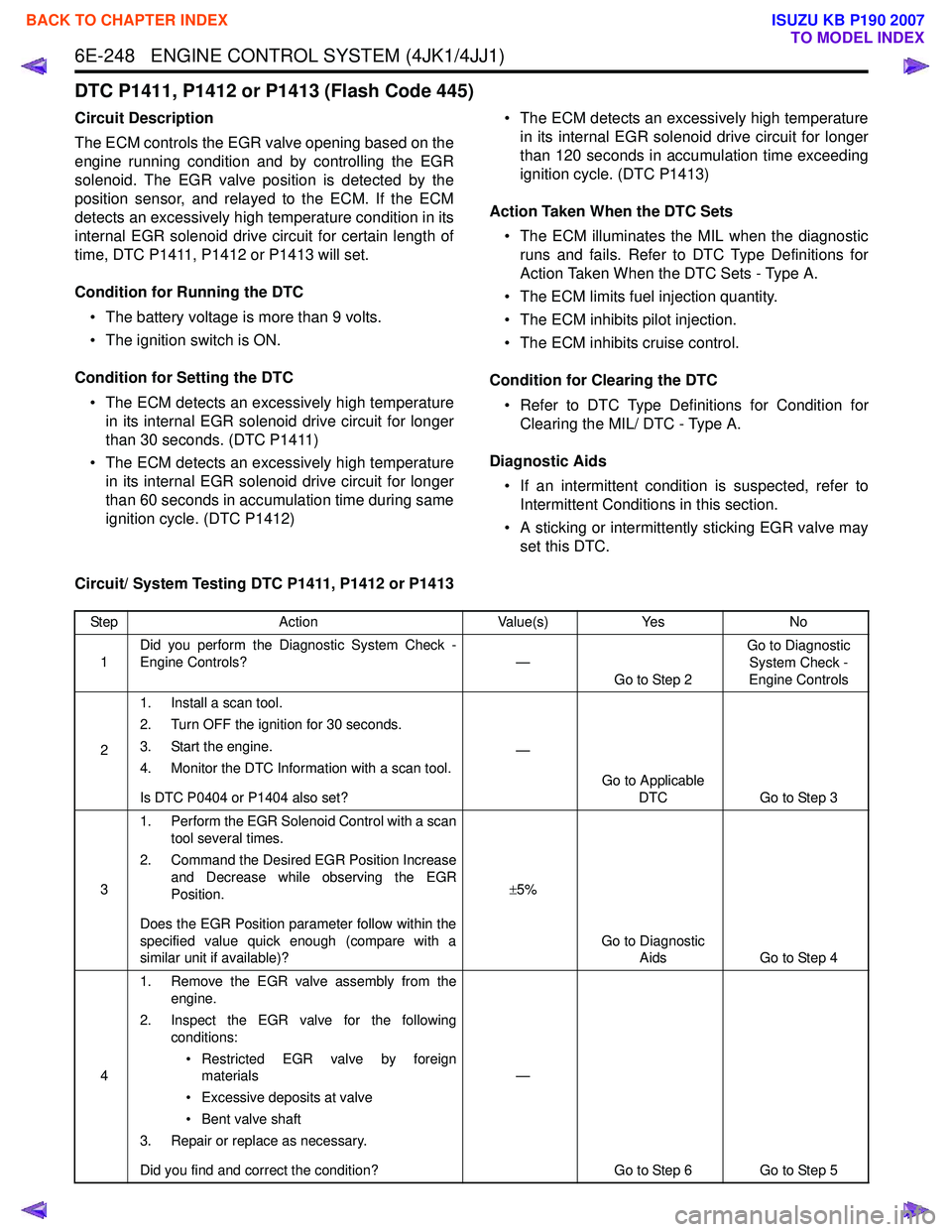
Circuit/ System Testing DTC P1411, P1412 or P1413
Step Action Value(s)Yes No
1 Did you perform the Diagnostic System Check -
Engine Controls? —
Go to Step 2 Go to Diagnostic
System Check -
Engine Controls
2 1. Install a scan tool.
2. Turn OFF the ignition for 30 seconds.
3. Start the engine.
4. Monitor the DTC Information with a scan tool.
Is DTC P0404 or P1404 also set? —
Go to Applicable DTC Go to Step 3
3 1. Perform the EGR Solenoid Control with a scan
tool several times.
2. Command the Desired EGR Position Increase and Decrease while observing the EGR
Position.
Does the EGR Position parameter follow within the
specified value quick enough (compare with a
similar unit if available)? ±
5%
Go to Diagnostic Aids Go to Step 4
4 1. Remove the EGR valve assembly from the
engine.
2. Inspect the EGR valve for the following conditions:
• Restricted EGR valve by foreign materials
• Excessive deposits at valve
• Bent valve shaft
3. Repair or replace as necessary.
Did you find and correct the condition? —
Go to Step 6 Go to Step 5
BACK TO CHAPTER INDEX
TO MODEL INDEX
ISUZU KB P190 2007
Page 1867 of 6020
6E-250 ENGINE CONTROL SYSTEM (4JK1/4JJ1)
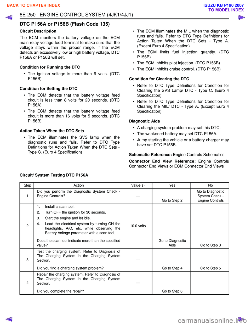
DTC P156A or P156B (Flash Code 135)
Circuit Description
The ECM monitors the battery voltage on the ECM
main relay voltage feed terminal to make sure that the
voltage stays within the proper range. If the ECM
detects an excessively low or high battery voltage, DTC
P156A or P156B will set.
Condition for Running the DTC • The ignition voltage is more than 9 volts. (DTC P156B)
Condition for Setting the DTC • The ECM detects that the battery voltage feed circuit is less than 8 volts for 20 seconds. (DTC
P156A)
• The ECM detects that the battery voltage feed circuit is more than 16 volts for 5 seconds. (DTC
P156B)
Action Taken When the DTC Sets • The ECM illuminates the SVS lamp when the diagnostic runs and fails. Refer to DTC Type
Definitions for Action Taken When the DTC Sets -
Type C. (Euro 4 Specification) • The ECM illuminates the MIL when the diagnostic
runs and fails. Refer to DTC Type Definitions for
Action Taken When the DTC Sets - Type A.
(Except Euro 4 Specification)
• The ECM limits fuel injection quantity. (DTC P156B)
• The ECM inhibits pilot injection. (DTC P156B)
• The ECM inhibits cruise control. (DTC P156B)
Condition for Clearing the DTC • Refer to DTC Type Definitions for Condition for Clearing the SVS Lamp/ DTC - Type C. (Euro 4
Specification)
• Refer to DTC Type Definitions for Condition for Clearing the MIL/ DTC - Type A. (Except Euro 4
Specification)
Diagnostic Aids • A charging system problem may set this DTC.
• The weakened battery may set DTC P156A.
• Jump starting the vehicle or a battery charger may have set DTC P156B.
Schematic Reference: Engine Controls Schematics
Connector End View Reference: Engine Controls
Connector End Views or ECM Connector End Views
Circuit/ System Testing DTC P156A
Step Action Value(s)Yes No
1 Did you perform the Diagnostic System Check -
Engine Controls? —
Go to Step 2 Go to Diagnostic
System Check -
Engine Controls
2 1. Install a scan tool.
2. Turn OFF the ignition for 30 seconds.
3. Start the engine and let idle.
4. Load the electrical system by turning ON the headlights, A/C, etc. while observing the
Battery Voltage parameter with a scan tool.
Does the scan tool indicate more than the specified
value? 10.0 volts
Go to Diagnostic Aids Go to Step 3
3 Test the charging system. Refer to Diagnosis of
The Charging System in the Charging System
Section.
Did you find a charging system problem? —
Go to Step 4 Go to Step 5
4 Repair the charging system. Refer to Diagnosis of
The Charging System in the Charging System
Section.
Did you complete the repair? —
Go to Step 6
—
BACK TO CHAPTER INDEX
TO MODEL INDEX
ISUZU KB P190 2007
Page 1868 of 6020
ENGINE CONTROL SYSTEM (4JK1/4JJ1) 6E-251
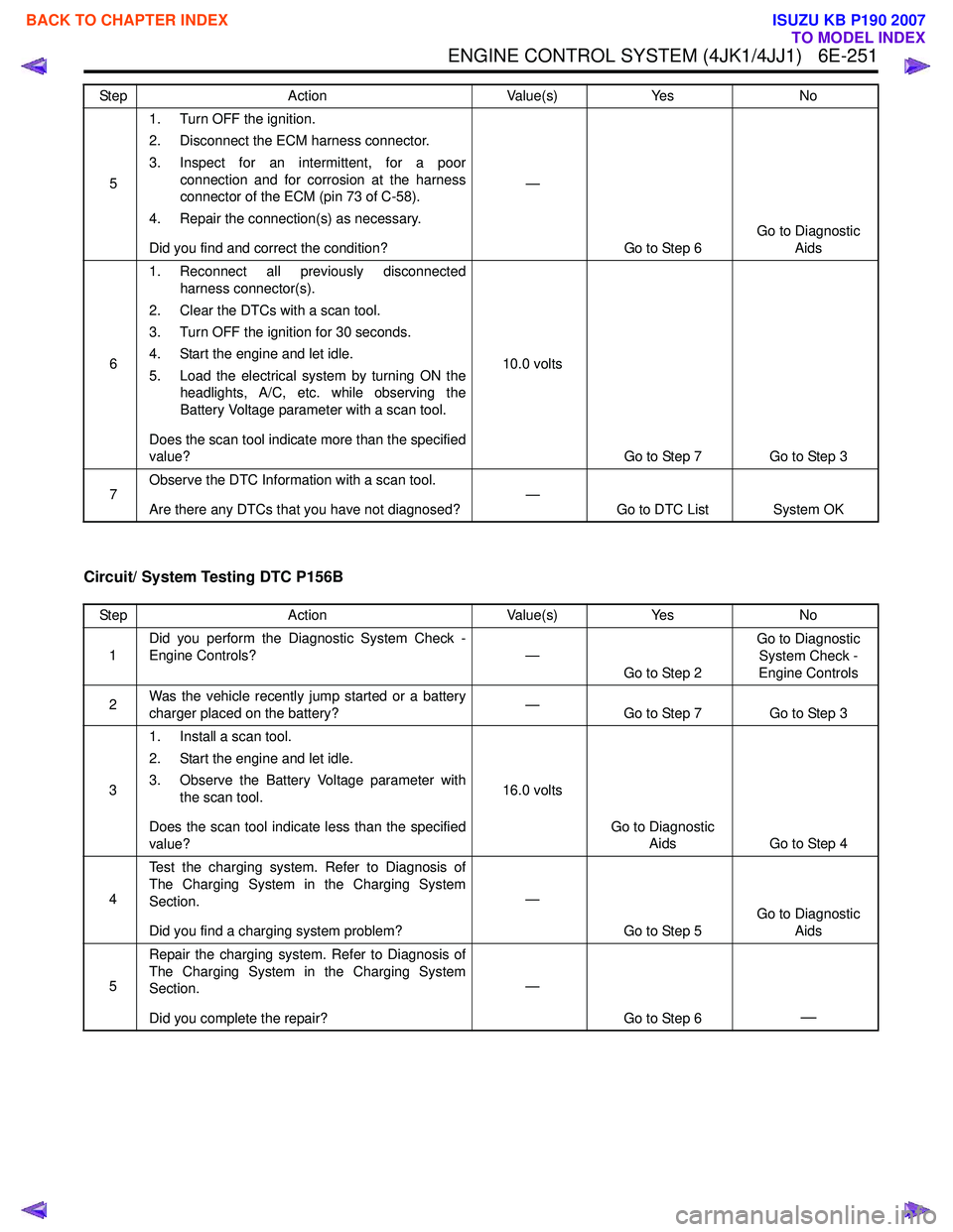
Circuit/ System Testing DTC P156B
51. Turn OFF the ignition.
2. Disconnect the ECM harness connector.
3. Inspect for an intermittent, for a poor connection and for corrosion at the harness
connector of the ECM (pin 73 of C-58).
4. Repair the connection(s) as necessary.
Did you find and correct the condition? —
Go to Step 6 Go to Diagnostic
Aids
6 1. Reconnect all previously disconnected
harness connector(s).
2. Clear the DTCs with a scan tool.
3. Turn OFF the ignition for 30 seconds.
4. Start the engine and let idle.
5. Load the electrical system by turning ON the headlights, A/C, etc. while observing the
Battery Voltage parameter with a scan tool.
Does the scan tool indicate more than the specified
value? 10.0 volts
Go to Step 7 Go to Step 3
7 Observe the DTC Information with a scan tool.
Are there any DTCs that you have not diagnosed? —
Go to DTC List System OK
Step
Action Value(s)Yes No
Step Action Value(s)Yes No
1 Did you perform the Diagnostic System Check -
Engine Controls? —
Go to Step 2 Go to Diagnostic
System Check -
Engine Controls
2 Was the vehicle recently jump started or a battery
charger placed on the battery? —
Go to Step 7 Go to Step 3
3 1. Install a scan tool.
2. Start the engine and let idle.
3. Observe the Battery Voltage parameter with the scan tool.
Does the scan tool indicate less than the specified
value? 16.0 volts
Go to Diagnostic Aids Go to Step 4
4 Test the charging system. Refer to Diagnosis of
The Charging System in the Charging System
Section.
Did you find a charging system problem? —
Go to Step 5 Go to Diagnostic
Aids
5 Repair the charging system. Refer to Diagnosis of
The Charging System in the Charging System
Section.
Did you complete the repair? —
Go to Step 6
—
BACK TO CHAPTER INDEX
TO MODEL INDEX
ISUZU KB P190 2007
Page 1874 of 6020
ENGINE CONTROL SYSTEM (4JK1/4JJ1) 6E-257
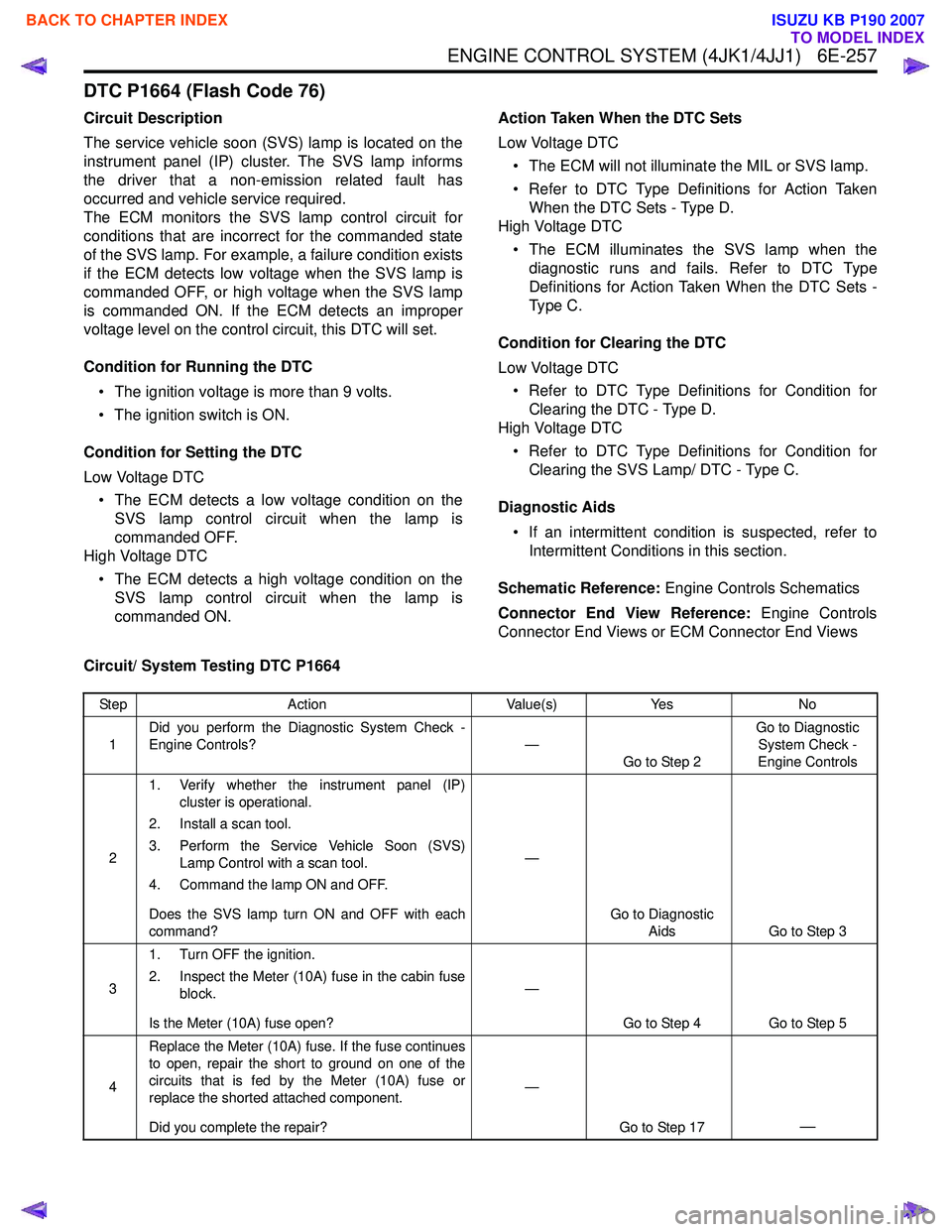
DTC P1664 (Flash Code 76)
Circuit Description
The service vehicle soon (SVS) lamp is located on the
instrument panel (IP) cluster. The SVS lamp informs
the driver that a non-emission related fault has
occurred and vehicle service required.
The ECM monitors the SVS lamp control circuit for
conditions that are incorrect for the commanded state
of the SVS lamp. For example, a failure condition exists
if the ECM detects low voltage when the SVS lamp is
commanded OFF, or high voltage when the SVS lamp
is commanded ON. If the ECM detects an improper
voltage level on the control circuit, this DTC will set.
Condition for Running the DTC • The ignition voltage is more than 9 volts.
• The ignition switch is ON.
Condition for Setting the DTC
Low Voltage DTC • The ECM detects a low voltage condition on the SVS lamp control circuit when the lamp is
commanded OFF.
High Voltage DTC
• The ECM detects a high voltage condition on the SVS lamp control circuit when the lamp is
commanded ON. Action Taken When the DTC Sets
Low Voltage DTC • The ECM will not illuminate the MIL or SVS lamp.
• Refer to DTC Type Definitions for Action Taken When the DTC Sets - Type D.
High Voltage DTC
• The ECM illuminates the SVS lamp when the diagnostic runs and fails. Refer to DTC Type
Definitions for Action Taken When the DTC Sets -
Type C.
Condition for Clearing the DTC
Low Voltage DTC • Refer to DTC Type Definitions for Condition for Clearing the DTC - Type D.
High Voltage DTC
• Refer to DTC Type Definitions for Condition for Clearing the SVS Lamp/ DTC - Type C.
Diagnostic Aids • If an intermittent condition is suspected, refer to Intermittent Conditions in this section.
Schematic Reference: Engine Controls Schematics
Connector End View Reference: Engine Controls
Connector End Views or ECM Connector End Views
Circuit/ System Testing DTC P1664
Step Action Value(s)Yes No
1 Did you perform the Diagnostic System Check -
Engine Controls? —
Go to Step 2 Go to Diagnostic
System Check -
Engine Controls
2 1. Verify whether the instrument panel (IP)
cluster is operational.
2. Install a scan tool.
3. Perform the Service Vehicle Soon (SVS) Lamp Control with a scan tool.
4. Command the lamp ON and OFF.
Does the SVS lamp turn ON and OFF with each
command? —
Go to Diagnostic Aids Go to Step 3
3 1. Turn OFF the ignition.
2. Inspect the Meter (10A) fuse in the cabin fuse block.
Is the Meter (10A) fuse open? —
Go to Step 4 Go to Step 5
4 Replace the Meter (10A) fuse. If the fuse continues
to open, repair the short to ground on one of the
circuits that is fed by the Meter (10A) fuse or
replace the shorted attached component.
Did you complete the repair? —
Go to Step 17
—
BACK TO CHAPTER INDEX
TO MODEL INDEX
ISUZU KB P190 2007