2007 ISUZU KB P190 torque
[x] Cancel search: torquePage 2473 of 6020
E N G IN E SPEED C O NTR O L S Y STEM ( C 24SE) 6 H-1
Service Precaution
WARNING: THIS VEHICLE HAS A SUPPLEMENTAL
RESTRAINT S
YSTEM (SRS). REFER TO THE SRS
COMPONENT AND WIRING LOCATION VIEW IN
ORDER TO DETERMINE WHETHER YOU ARE
PERFORMING SERVICE ON OR NEAR THE SRS
COMPONENTS OR THE SRS WIRING. WHEN YOU
ARE PERFORMING SERVICE ON OR NEAR THE
SRS COMPONENTS OR THE SRS WIRING, REFER
TO THE SRS SERVICE INFORMATION. FAILURE TO
FOLLOW WARNINGS COULD RESULT IN
POSSIBLE AIR BAG DEPLOYMENT, PERSONAL
INJURY, OR OTHERWISE UNNEEDED SRS SYSTEM
REPAIRS.
CAUTION: Always use the correct fastener in the
proper location. When you replace a fastener, use
ONLY the exact part number for that application.
ISUZU will call out those fasteners that require a
replacement after removal. ISUZU will also call out
the fasteners that require thread lockers or thread
sealant. UNLESS OTHERWISE SPECIFIED, do not
use supplemental coatings (Paints, greases, o
r
other corrosion inhibitors) on threaded fasteners or
fastener joint interfaces. Generally, such coatings
adversely affect the fastener torque and the joint
clamping force, and may damage the fastener.
When you install fasteners, use the correct
tightening sequence and specifications. Following
these instructions can help you avoid damage to
parts and systems.
BACK TO CHAPTER INDEX
TO MODEL INDEX
ISUZU KB P190 2007
Page 2477 of 6020
6J-2 INDUCTION
Service Precaution
CAUTION:
Always use the correct fastener in the proper location.
When you replace a fastener, use ONLY the exact part
number for that application. ISUZU will call out those
fasteners that require a replacement after removal. ISUZU
will also call out the fasteners that require thread lockers
or thread sealant. UNLESS OTHERWISE SPECIFIED, do
not use supplemental coatings (Paints, greases, or other
corrosion inhibitors) on threaded fasteners or fastener
joint interfaces. Generally, such coatings adversely affect
the fastener torque and the joint clamping force, and may
damage the fastener. When you install fasteners, use the
correct tightening sequence and specifications. Following
these instructions can help you avoid damage to parts
and systems.
RTW 46JSH000101
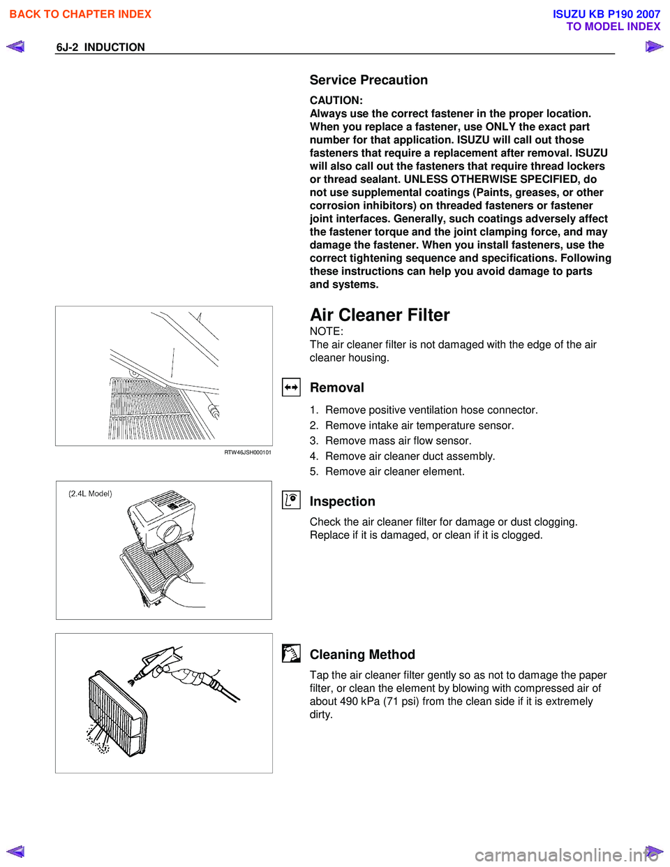
Air Cleaner Filter
NOTE:
The air cleaner filter is not damaged with the edge of the air
cleaner housing.
Removal
1. Remove positive ventilation hose connector.
2. Remove intake air temperature sensor.
3. Remove mass air flow sensor.
4. Remove air cleaner duct assembly.
5. Remove air cleaner element.
Inspection
Check the air cleaner filter for damage or dust clogging.
Replace if it is damaged, or clean if it is clogged.
Cleaning Method
Tap the air cleaner filter gently so as not to damage the paper
filter, or clean the element by blowing with compressed air of
about 490 kPa (71 psi) from the clean side if it is extremely
dirty.
BACK TO CHAPTER INDEX
TO MODEL INDEX
ISUZU KB P190 2007
Page 2480 of 6020
Engine Mechanical – V6 Page 6A1–1
6A1
Engine Mechanical – V6
ATTENTION
Before performing any service operation or other procedure described in this Section, refer to 1.1
WARNING, CAUTION and NOTES for correct workshop practices with regard to safety and/or property
damage.
1 General Information ............................................................................................................ ...................8
1.1 WARNING, CAUTION and NOTES .................................................................................................... ................... 8
Definition of WARNING, CAUTION and NOTE Statements ............................................................................. .... 8
WARNING defined ............................................................................................................................................. 8
CAUTION defined .............................................................................................................................................. 8
NOTE defined..................................................................................................................................................... 9
1.2 Engine Components .............................................................................................................................................. 9
Major Component Assemblies..................................................................................................... ......................... 9
Intake Manifold Assembly ................................................................................................................................... 10
Engine Front Cover.............................................................................................................................................. 12
Camshaft Timing Components ..................................................................................................... ...................... 13
Camshaft Cover Assembly.................................................................................................................................. 14
Cylinder Head Assembly ..................................................................................................................................... 15
Oil Pump ............................................................................................................................................................... 16
Engine Block Assembly .......................................................................................................... ............................ 17
Pistons, Rings, Bearing and Connecting Rod ..................................................................................... .............. 18
Oil Pan Assembly................................................................................................................................................. 19
Oil Filter Assembly .............................................................................................................................................. 20
1.3 Engine Serial Number........................................................................................................... ............................... 20
1.4 Engine Construction............................................................................................................................................ 21
Cylinder Block ...................................................................................................................................................... 21
Cylinder Heads ................................................................................................................. .................................... 21
Crankshaft ............................................................................................................................................................ 22
Pistons, Pins and Connecting Rods .............................................................................................. .................... 22
Camshaft Drive System ....................................................................................................................................... 22
1.5 Engine Lubrication System ...................................................................................................... ........................... 24
Lubrication Description....................................................................................................................................... 24
1.6 Service Notes ....................................................................................................................................................... 24
Cleanliness and Care........................................................................................................... ................................ 24
Replacing Engine Gaskets ....................................................................................................... ........................... 24
Re-Using Gaskets and Applying Sealants......................................................................................... ............... 24
Separating Components................................................................................................................................... 24
Cleaning Gasket Surfaces................................................................................................................................ 24
Assembling Components .......................................................................................................... ....................... 25
Use of Room Temperature Vulcanising and Anaerobic Sealer....................................................................... .25
Room Temperature Vulcanising Sealer............................................................................................................ 25
Anaerobic Sealer .............................................................................................................................................. 25
Pipe Joint Compound ............................................................................................................ ........................... 26
Separating Parts .................................................................................................................................................. 26
Tools and Equipment ............................................................................................................ .............................. 26
Fasteners .............................................................................................................................................................. 27
Clamp Load ..................................................................................................................... ................................. 27
Torque Angle and Torque to Yield Fasteners..................................................................................... .............. 27
2 Diagnosis ..............................................................................................................................................28
2.1 Engine Diagnosis ............................................................................................................... .................................. 28
2.2 Symptoms............................................................................................................................................................. 28
Strategy Based Diagnosis ....................................................................................................... ............................ 28
BACK TO CHAPTER INDEX
TO MODEL INDEX
ISUZU KB P190 2007
Page 2486 of 6020
Engine Mechanical – V6 Page 6A1–7
Engine Block Right-hand Deck Face................................................................................................................ 279
Engine Front Cover............................................................................................................................................ 280
Upper Intake Manifold Top ...................................................................................................... .......................... 281
Upper Intake Manifold Front .................................................................................................... ......................... 282
Upper Intake Manifold Rear............................................................................................................................... 283
Lower Intake Manifold Top ................................................................................................................................ 284
Oil Pan Front ...................................................................................................................................................... 285
Oil Pan Rear........................................................................................................................................................ 286
Oil Pan Bottom ................................................................................................................. .................................. 287
5 Specifications .....................................................................................................................................288
6 Torque Wrench Specifications................................................................................................... .......292
7 Special Tools ......................................................................................................................................294
BACK TO CHAPTER INDEX
TO MODEL INDEX
ISUZU KB P190 2007
Page 2504 of 6020
Engine Mechanical – V6 Page 6A1–25
• Do not use any other method or technique to remove sealant or gasket material from a part.
• Do not use abrasive pads, sand paper, or power tools to clean the gasket surfaces as these methods of cleaning
can cause damage to the component sealing surfaces. Abrasive pads also produce fine grit that the oil filter cannot
remove from the oil. This grit is abrasive and has been known to cause internal engine damage.
Assembling Components
• W hen assembling components, use only the sealant specified or equivalent in the service procedure.
• Sealing surfaces should be clean and free of debris or oil.
• Specific components such as crankshaft oil seals or valve stem oil seals may require lubrication during assembly.
• Components requiring lubrication will be identified in the service procedure.
• W hen applying sealant to a component, apply the amount specified in the service procedure.
• Do not allow the sealant to enter into any blind threaded holes as it may prevent the bolt from clamping correctly or
cause component damage when tightened.
• Only ever tighten bolts to the correct torque specification. Do not over-tighten.
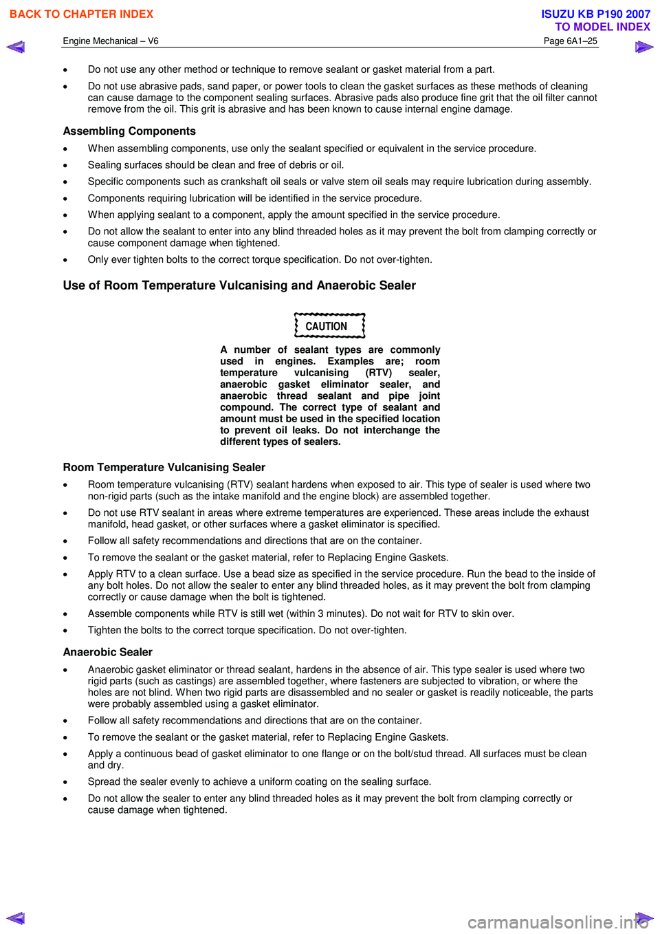
Use of Room Temperature Vulcanising and Anaerobic Sealer
CAUTION
A number of sealant types are commonly
used in engines. Examples are; room
temperature vulcanising (RTV) sealer,
anaerobic gasket eliminator sealer, and
anaerobic thread sealant and pipe joint
compound. The correct type of sealant and
amount must be used in the specified location
to prevent oil leaks. Do not interchange the
different types of sealers.
Room Temperature Vulcanising Sealer
• Room temperature vulcanising (RTV) sealant hardens when exposed to air. This type of sealer is used where two
non-rigid parts (such as the intake manifold and the engine block) are assembled together.
• Do not use RTV sealant in areas where extreme temperatures are experienced. These areas include the exhaust
manifold, head gasket, or other surfaces where a gasket eliminator is specified.
• Follow all safety recommendations and directions that are on the container.
• To remove the sealant or the gasket material, refer to Replacing Engine Gaskets.
• Apply RTV to a clean surface. Use a bead size as specified in the service procedure. Run the bead to the inside of
any bolt holes. Do not allow the sealer to enter any blind threaded holes, as it may prevent the bolt from clamping
correctly or cause damage when the bolt is tightened.
• Assemble components while RTV is still wet (within 3 minutes). Do not wait for RTV to skin over.
• Tighten the bolts to the correct torque specification. Do not over-tighten.
Anaerobic Sealer
• Anaerobic gasket eliminator or thread sealant, hardens in the absence of air. This type sealer is used where two
rigid parts (such as castings) are assembled together, where fasteners are subjected to vibration, or where the
holes are not blind. W hen two rigid parts are disassembled and no sealer or gasket is readily noticeable, the parts
were probably assembled using a gasket eliminator.
• Follow all safety recommendations and directions that are on the container.
• To remove the sealant or the gasket material, refer to Replacing Engine Gaskets.
• Apply a continuous bead of gasket eliminator to one flange or on the bolt/stud thread. All surfaces must be clean
and dry.
• Spread the sealer evenly to achieve a uniform coating on the sealing surface.
• Do not allow the sealer to enter any blind threaded holes as it may prevent the bolt from clamping correctly or
cause damage when tightened.
BACK TO CHAPTER INDEX
TO MODEL INDEX
ISUZU KB P190 2007
Page 2505 of 6020
Engine Mechanical – V6 Page 6A1–26
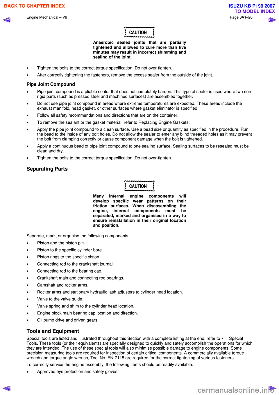
CAUTION
Anaerobic sealed joints that are partially
tightened and allowed to cure more than five
minutes may result in incorrect shimming and
sealing of the joint.
• Tighten the bolts to the correct torque specification. Do not over-tighten.
• After correctly tightening the fasteners, remove the excess sealer from the outside of the joint.
Pipe Joint Compound
• Pipe joint compound is a pliable sealer that does not completely harden. This type of sealer is used where two non-
rigid parts (such as pressed steel and machined surfaces) are assembled together.
• Do not use pipe joint compound in areas where extreme temperatures are expected. These areas include the
exhaust manifold, head gasket, or other surfaces where gasket eliminator is specified.
• Follow all safety recommendations and directions that are on the container.
• To remove the sealant or the gasket material, refer to Replacing Engine Gaskets.
• Apply the pipe joint compound to a clean surface. Use a bead size or quantity as specified in the procedure. Run
the bead to the inside of any bolt holes. Do not allow the sealer to enter any blind threaded holes as it may prevent
the bolt from clamping correctly or cause component damage when the bolt is tightened.
• Apply a continuous bead of pipe joint compound to one sealing surface. Sealing surfaces to be resealed must be
clean and dry.
• Tighten the bolts to the correct torque specification. Do not over-tighten.
Separating Parts
CAUTION
Many internal engine components will
develop specific wear patterns on their
friction surfaces. When disassembling the
engine, internal components must be
separated, marked and organised in a way to
ensure reinstallation in their original location
and position.
Separate, mark, or organise the following components:
• Piston and the piston pin.
• Piston to the specific cylinder bore.
• Piston rings to the specific piston.
• Connecting rod to the crankshaft journal.
• Connecting rod to the bearing cap.
• Crankshaft main and connecting rod bearings.
• Camshaft and rocker arms.
• Rocker arms and stationary hydraulic lash adjusters to cylinder head location.
• Valve to the valve guide.
• Valve spring and shim to the cylinder head location.
• Engine block main bearing cap location and direction.
• Oil pump drive and driven gears.
Tools and Equipment
Special tools are listed and illustrated throughout this Section with a complete listing at the end, refer to 7 Special
Tools. These tools (or their equivalents) are specially designed to quickly and safely accomplish the operations for which
they are intended. The use of these special tools will also minimise possible damage to engine components. Some
precision measuring tools are required for inspection of certain critical components. A commercially available torque
wrench and torque angle wrench, Tool No. EN-7115 are required for the correct tightening of various fasteners.
To correctly service the engine assembly, the following items should be readily available:
• Approved eye protection and safety gloves.
BACK TO CHAPTER INDEX
TO MODEL INDEX
ISUZU KB P190 2007
Page 2506 of 6020
Engine Mechanical – V6 Page 6A1–27
• A clean, well-lit, work area.
• A suitable parts cleaning tank.
• A compressed air supply.
• Trays or storage containers to keep parts and fasteners organised.
• An adequate set of hand tools.
• Approved engine repair stand.
• An approved engine lifting device that will adequately support the weight of the components.
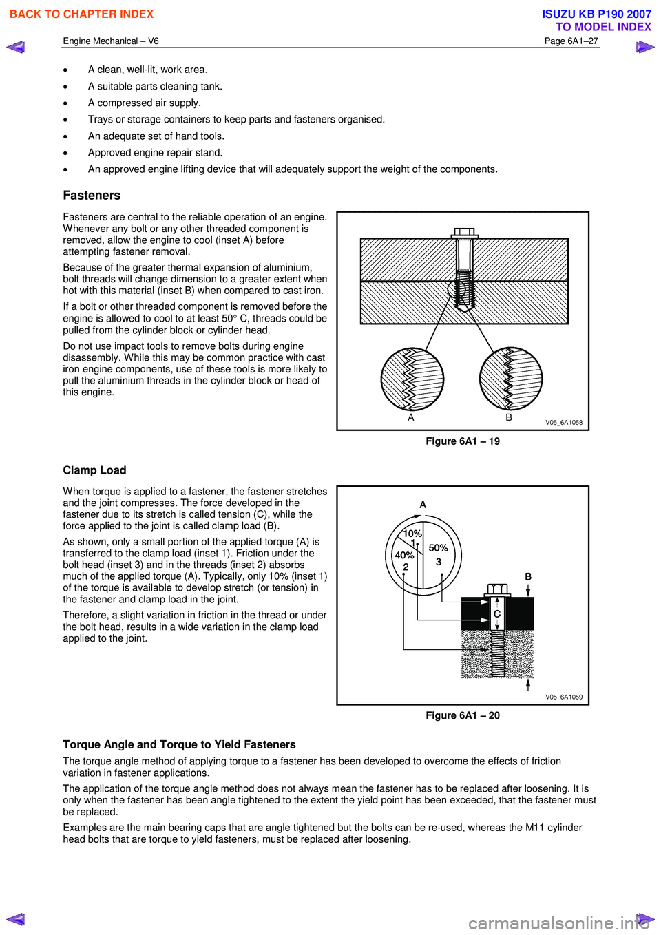
Fasteners
Fasteners are central to the reliable operation of an engine.
W henever any bolt or any other threaded component is
removed, allow the engine to cool (inset A) before
attempting fastener removal.
Because of the greater thermal expansion of aluminium,
bolt threads will change dimension to a greater extent when
hot with this material (inset B) when compared to cast iron.
If a bolt or other threaded component is removed before the
engine is allowed to cool to at least 50 ° C, threads could be
pulled from the cylinder block or cylinder head.
Do not use impact tools to remove bolts during engine
disassembly. W hile this may be common practice with cast
iron engine components, use of these tools is more likely to
pull the aluminium threads in the cylinder block or head of
this engine.
Figure 6A1 – 19
Clamp Load
W hen torque is applied to a fastener, the fastener stretches
and the joint compresses. The force developed in the
fastener due to its stretch is called tension (C), while the
force applied to the joint is called clamp load (B).
As shown, only a small portion of the applied torque (A) is
transferred to the clamp load (inset 1). Friction under the
bolt head (inset 3) and in the threads (inset 2) absorbs
much of the applied torque (A). Typically, only 10% (inset 1)
of the torque is available to develop stretch (or tension) in
the fastener and clamp load in the joint.
Therefore, a slight variation in friction in the thread or under
the bolt head, results in a wide variation in the clamp load
applied to the joint.
Figure 6A1 – 20
Torque Angle and Torque to Yield Fasteners
The torque angle method of applying torque to a fastener has been developed to overcome the effects of friction
variation in fastener applications.
The application of the torque angle method does not always mean the fastener has to be replaced after loosening. It is
only when the fastener has been angle tightened to the extent the yield point has been exceeded, that the fastener must
be replaced.
Examples are the main bearing caps that are angle tightened but the bolts can be re-used, whereas the M11 cylinder
head bolts that are torque to yield fasteners, must be replaced after loosening.
BACK TO CHAPTER INDEX
TO MODEL INDEX
ISUZU KB P190 2007
Page 2513 of 6020
Engine Mechanical – V6 Page 6A1–34
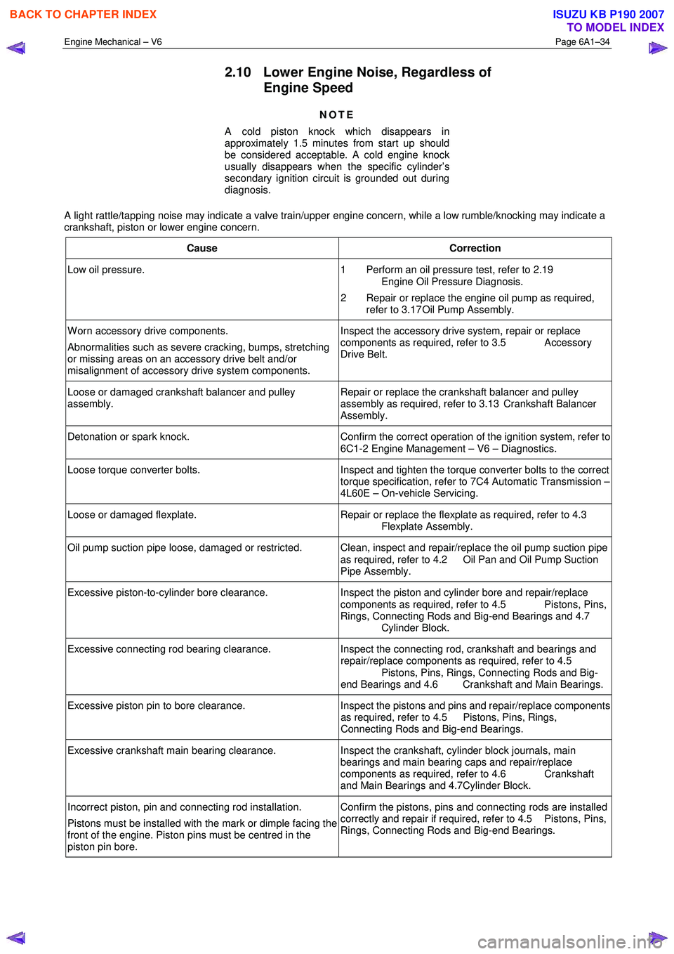
2.10 Lower Engine Noise, Regardless of
Engine Speed
NOTE
A cold piston knock which disappears in
approximately 1.5 minutes from start up should
be considered acceptable. A cold engine knock
usually disappears when the specific cylinder’s
secondary ignition circuit is grounded out during
diagnosis.
A light rattle/tapping noise may indicate a valve train/upper engine concern, while a low rumble/knocking may indicate a
crankshaft, piston or lower engine concern.
Cause Correction
Low oil pressure. 1 Perform an oil pressure test, refer to 2.19
Engine Oil Pressure Diagnosis.
2 Repair or replace the engine oil pump as required, refer to 3.17 Oil Pump Assembly.
W orn accessory drive components.
Abnormalities such as severe cracking, bumps, stretching
or missing areas on an accessory drive belt and/or
misalignment of accessory drive system components. Inspect the accessory drive system, repair or replace
components as required, refer to 3.5 Accessory
Drive Belt.
Loose or damaged crankshaft balancer and pulley
assembly. Repair or replace the crankshaft balancer and pulley
assembly as required, refer to 3.13 Crankshaft Balancer
Assembly.
Detonation or spark knock. Confirm the correct operation of the ignition system, refer to
6C1-2 Engine Management – V6 – Diagnostics.
Loose torque converter bolts. Inspect and tighten the torque converter bolts to the correct
torque specification, refer to 7C4 Automatic Transmission –
4L60E – On-vehicle Servicing.
Loose or damaged flexplate. Repair or replace the flexplate as required, refer to 4.3
Flexplate Assembly.
Oil pump suction pipe loose, damaged or restricted. Clean, inspect and repair/replace the oil pump suction pipe as required, refer to 4.2 Oil Pan and Oil Pump Suction
Pipe Assembly.
Excessive piston-to-cylinder bore clearance. Inspect the piston and cylinder bore and repair/replace
components as required, refer to 4.5 Pistons, Pins,
Rings, Connecting Rods and Big-end Bearings and 4.7
Cylinder Block.
Excessive connecting rod bearing clearance. Inspect the connecting rod, crankshaft and bearings and
repair/replace components as required, refer to 4.5
Pistons, Pins, Rings, Connecting Rods and Big-
end Bearings and 4.6 Crankshaft and Main Bearings.
Excessive piston pin to bore clearance. Inspect the pistons and pins and repair/replace components
as required, refer to 4.5 Pistons, Pins, Rings,
Connecting Rods and Big-end Bearings.
Excessive crankshaft main bearing clearance. Inspect the crankshaft, cylinder block journals, main
bearings and main bearing caps and repair/replace
components as required, refer to 4.6 Crankshaft
and Main Bearings and 4.7Cylinder Block.
Incorrect piston, pin and connecting rod installation.
Pistons must be installed with the mark or dimple facing the
front of the engine. Piston pins must be centred in the
piston pin bore. Confirm the pistons, pins and connecting rods are installed
correctly and repair if required, refer to 4.5 Pistons, Pins,
Rings, Connecting Rods and Big-end Bearings.
BACK TO CHAPTER INDEX
TO MODEL INDEX
ISUZU KB P190 2007