Page 2604 of 6020
Engine Mechanical – V6 Page 6A1–125
13 Install the primary timing chain upper guide (1).
14 Install the primary timing chain upper guide bolts (2) and tighten to the correct torque specification.
Primary timing chain upper guide
attaching bolt torque specification ...........20.0 – 26.0 Nm
Figure 6A1 – 179
15 Ensure that the primary timing chain tensioner is being installed.
Figure 6A1 – 180
16 Reset the primary timing chain tensioner.
NOTE
To reset the tensioner, use a suitably sized flat
blade screwdriver (1) or Tool No. J 45027 (4) to
wind the plunger in a clockwise direction, into
the tensioner shaft (2).
Figure 6A1 – 181
BACK TO CHAPTER INDEX
TO MODEL INDEX
ISUZU KB P190 2007
Page 2606 of 6020
Engine Mechanical – V6 Page 6A1–127
23 Place the primary timing chain tensioner (2) into
position and loosely install the bolts (1) to the engine
block.
Figure 6A1 – 185
24 Verify the proper placement of the primary timing chain tensioner gasket tab (1).
25 Tighten the primary timing chain tensioner bolts (2) to the correct torque specification.
Primary timing chain tensioner
attaching bolt torque specification ...........20.0 – 26.0 Nm
Figure 6A1 – 186
26 Release the primary timing chain tensioner (1) by pulling out Tool No. EN 46112 (2) and unlocking the
tensioner shaft.
Figure 6A1 – 187
BACK TO CHAPTER INDEX
TO MODEL INDEX
ISUZU KB P190 2007
Page 2611 of 6020
Engine Mechanical – V6 Page 6A1–132
11 Position the chain guide (2).
12 Install the secondary timing chain guide bolts (1) and tighten to the correct torque specification.
Secondary timing chain guide
attaching bolt torque specification ...........20.0 – 26.0 Nm
Figure 6A1 – 199
13 Ensure the right-hand secondary timing chain shoe is selected and orientated correctly.
CAUTION
The right-hand secondary camshaft drive
shoe is marked with the letters ‘RH’. Ensure
that the right-hand drive shoe is used when
installing to the right-hand side in this
procedure and that the letters ‘RH” are
facing the front of the vehicle when installed.
Figure 6A1 – 200
14 Position the right-hand secondary timing chain shoe (1).
Figure 6A1 – 201
BACK TO CHAPTER INDEX
TO MODEL INDEX
ISUZU KB P190 2007
Page 2612 of 6020
Engine Mechanical – V6 Page 6A1–133
15 Install the secondary timing chain shoe bolt (1) and
tighten to the correct torque specification.
Secondary timing chain shoe
attaching bolt torque specification ...........20.0 – 26.0 Nm
Figure 6A1 – 202
16 Ensure the right-hand secondary timing chain tensioner is selected and orientated correctly.
Figure 6A1 – 203
17 Reset the right-hand secondary timing chain tensioner.
NOTE
To reset the tensioner, use a suitably sized flat
blade screwdriver (1) or Tool No. J 45027 to
wind the plunger in a clockwise direction, into
the tensioner shaft (2).
Figure 6A1 – 204
BACK TO CHAPTER INDEX
TO MODEL INDEX
ISUZU KB P190 2007
Page 2614 of 6020
Engine Mechanical – V6 Page 6A1–135
24 Place the right-hand secondary timing chain tensioner
(2) into position and loosely install the bolts (1) to the
engine block.
Figure 6A1 – 208
25 Verify the proper placement of the right-hand secondary timing chain tensioner gasket tab (1).
26 Tighten the right-hand secondary timing chain tensioner bolts (2) to the correct torque specification.
Secondary timing chain tensioner
attaching bolt torque specification ...........20.0 – 26.0 Nm
Figure 6A1 – 209
27 Release the right-hand timing chain tensioner (1) by pulling out Tool No. EN 46112 (2) and unlocking the
tensioner plunger.
CAUTION
If Tool No. EN 46112 (1) is not removed from
the tensioner body (2), the plunger will
remain in the locked position and no tension
will be placed on the timing chain, this will
cause damage to the engine.
Figure 6A1 – 210
BACK TO CHAPTER INDEX
TO MODEL INDEX
ISUZU KB P190 2007
Page 2620 of 6020

Engine Mechanical – V6 Page 6A1–141
Reassemble
CAUTION
As there are no serviceable components
within the oil pump, a disassembled oil pump
must be replaced.
Reinstall
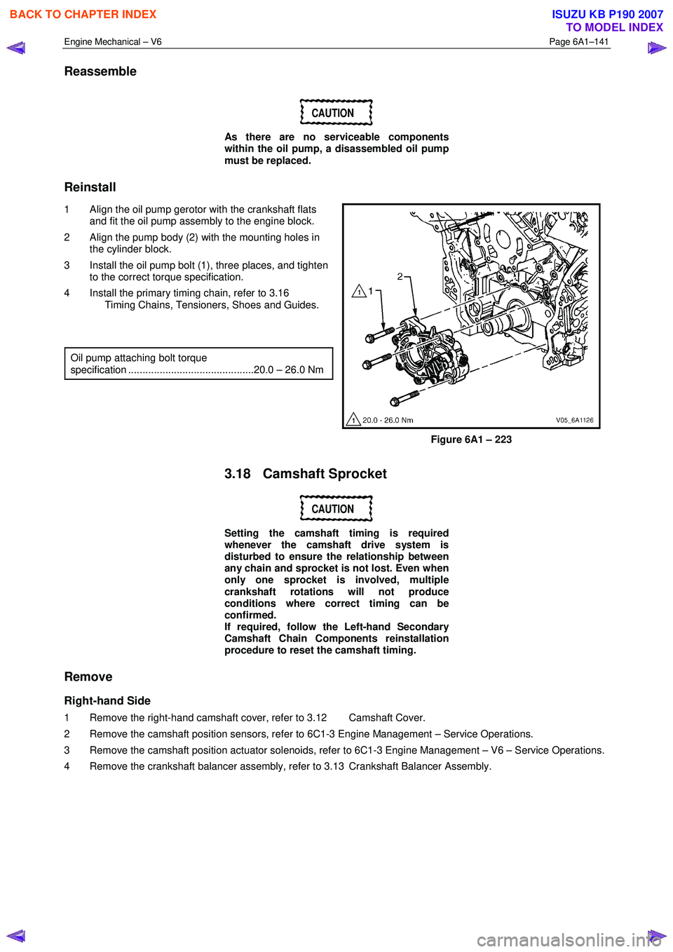
1 Align the oil pump gerotor with the crankshaft flats and fit the oil pump assembly to the engine block.
2 Align the pump body (2) with the mounting holes in the cylinder block.
3 Install the oil pump bolt (1), three places, and tighten to the correct torque specification.
4 Install the primary timing chain, refer to 3.16 Timing Chains, Tensioners, Shoes and Guides.
Oil pump attaching bolt torque
specification ............................................20.0 – 26.0 Nm
Figure 6A1 – 223
3.18 Camshaft Sprocket
CAUTION
Setting the camshaft timing is required
whenever the camshaft drive system is
disturbed to ensure the relationship between
any chain and sprocket is not lost. Even when
only one sprocket is involved, multiple
crankshaft rotations will not produce
conditions where correct timing can be
confirmed.
If required, follow the Left-hand Secondary
Camshaft Chain Components reinstallation
procedure to reset the camshaft timing.
Remove
Right-hand Side
1 Remove the right-hand camshaft cover, refer to 3.12 Camshaft Cover.
2 Remove the camshaft position sensors, refer to 6C1-3 Engine Management – Service Operations.
3 Remove the camshaft position actuator solenoids, refer to 6C1-3 Engine Management – V6 – Service Operations.
4 Remove the crankshaft balancer assembly, refer to 3.13 Crankshaft Balancer Assembly.
BACK TO CHAPTER INDEX
TO MODEL INDEX
ISUZU KB P190 2007
Page 2626 of 6020

Engine Mechanical – V6 Page 6A1–147
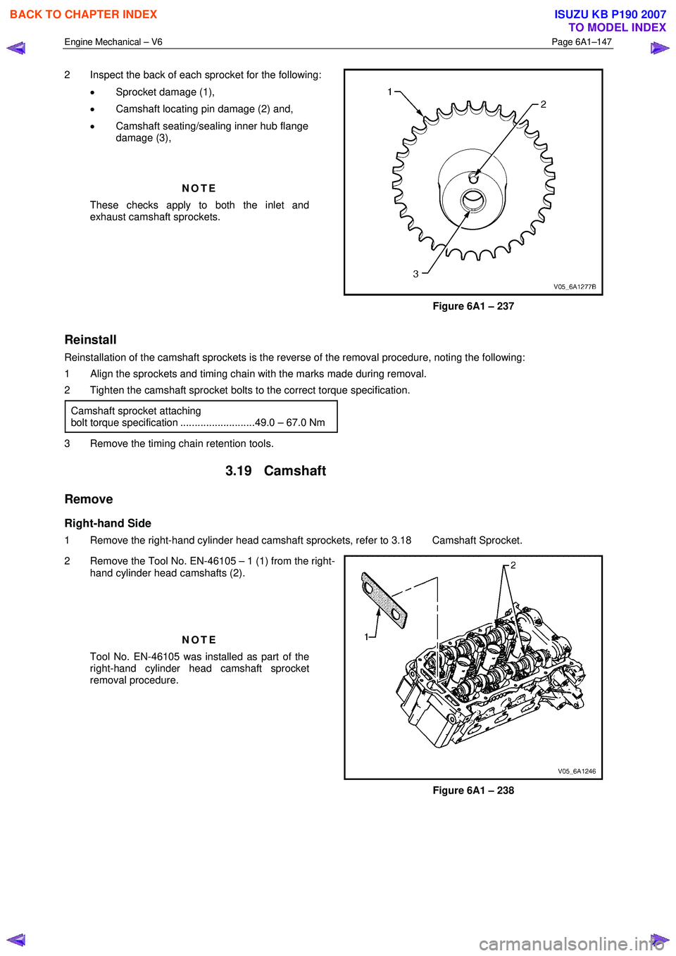
2 Inspect the back of each sprocket for the following:
• Sprocket damage (1),
• Camshaft locating pin damage (2) and,
• Camshaft seating/sealing inner hub flange
damage (3),
NOTE
These checks apply to both the inlet and
exhaust camshaft sprockets.
Figure 6A1 – 237
Reinstall
Reinstallation of the camshaft sprockets is the reverse of the removal procedure, noting the following:
1 Align the sprockets and timing chain with the marks made during removal.
2 Tighten the camshaft sprocket bolts to the correct torque specification.
Camshaft sprocket attaching
bolt torque specification ..........................49.0 – 67.0 Nm
3 Remove the timing chain retention tools.
3.19 Camshaft
Remove
Right-hand Side
1 Remove the right-hand cylinder head camshaft sprockets, refer to 3.18 Camshaft Sprocket.
2 Remove the Tool No. EN-46105 – 1 (1) from the right- hand cylinder head camshafts (2).
NOTE
Tool No. EN-46105 was installed as part of the
right-hand cylinder head camshaft sprocket
removal procedure.
Figure 6A1 – 238
BACK TO CHAPTER INDEX
TO MODEL INDEX
ISUZU KB P190 2007
Page 2634 of 6020

Engine Mechanical – V6 Page 6A1–155
9 Install the camshaft bearing thrust cap (1) in the first
journal of the right-hand cylinder head.
10 Install the remaining bearing caps (2) with their orientation mark toward the centre of the cylinder
head.
11 Hand start all the camshaft bearing cap bolts (3).
Figure 6A1 – 259
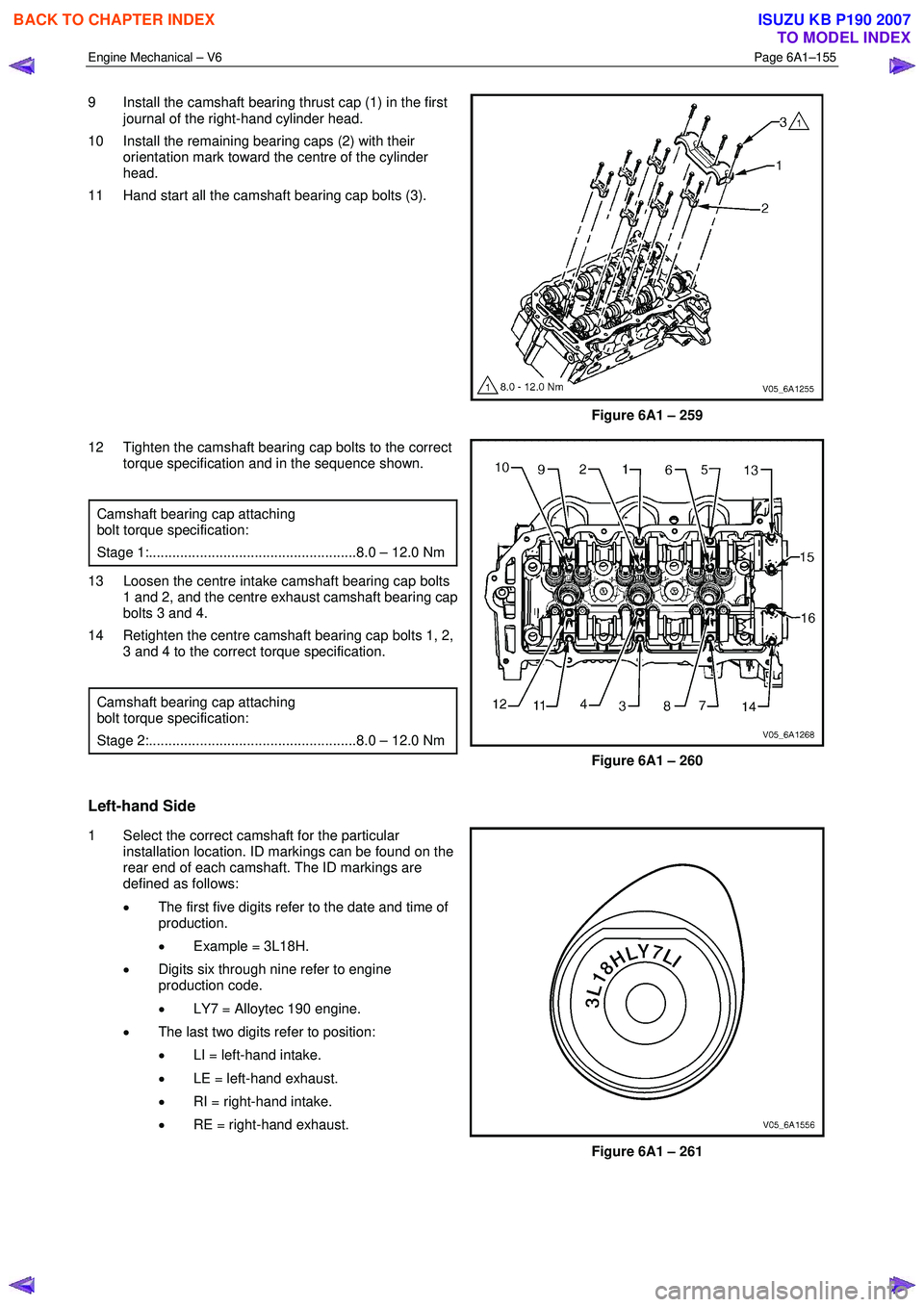
12 Tighten the camshaft bearing cap bolts to the correct torque specification and in the sequence shown.
Camshaft bearing cap attaching
bolt torque specification:
Stage 1:.....................................................8.0 – 12.0 Nm
13 Loosen the centre intake camshaft bearing cap bolts 1 and 2, and the centre exhaust camshaft bearing cap
bolts 3 and 4.
14 Retighten the centre camshaft bearing cap bolts 1, 2, 3 and 4 to the correct torque specification.
Camshaft bearing cap attaching
bolt torque specification:
Stage 2:.....................................................8.0 – 12.0 Nm
Figure 6A1 – 260
Left-hand Side
1 Select the correct camshaft for the particular installation location. ID markings can be found on the
rear end of each camshaft. The ID markings are
defined as follows:
• The first five digits refer to the date and time of
production.
• Example = 3L18H.
• Digits six through nine refer to engine
production code.
• LY7 = Alloytec 190 engine.
• The last two digits refer to position:
• LI = left-hand intake.
• LE = left-hand exhaust.
• RI = right-hand intake.
• RE = right-hand exhaust.
Figure 6A1 – 261
BACK TO CHAPTER INDEX
TO MODEL INDEX
ISUZU KB P190 2007