2007 ISUZU KB P190 torque
[x] Cancel search: torquePage 2713 of 6020
Engine Mechanical – V6 Page 6A1–234
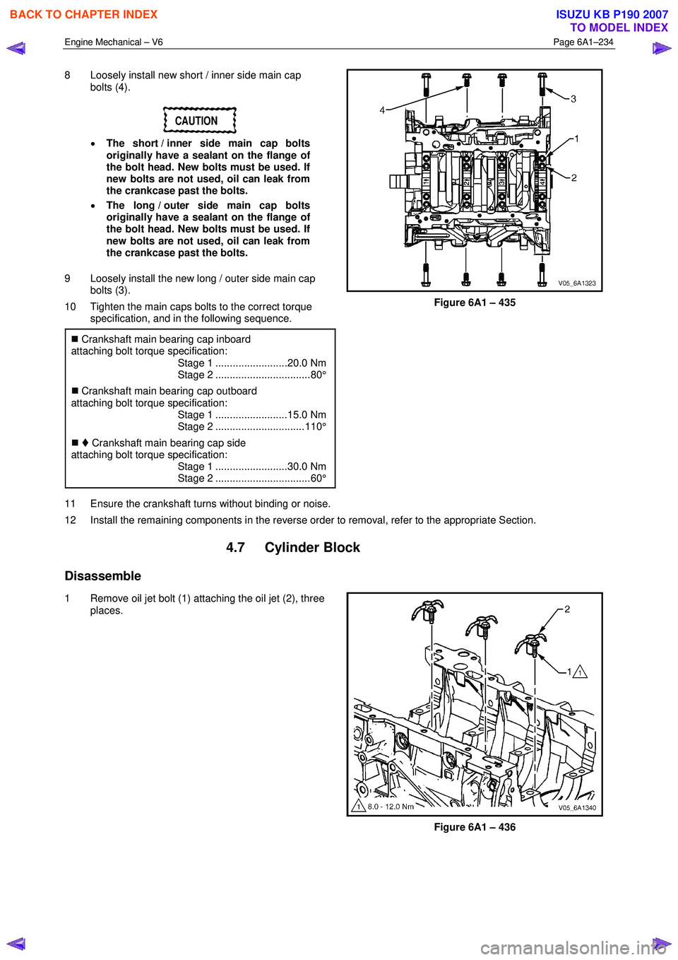
8 Loosely install new short / inner side main cap
bolts (4).
CAUTION
• The short / inner side main cap bolts
originally have a sealant on the flange of
the bolt head. New bolts must be used. If
new bolts are not used, oil can leak from
the crankcase past the bolts.
• The long / outer side main cap bolts
originally have a sealant on the flange of
the bolt head. New bolts must be used. If
new bolts are not used, oil can leak from
the crankcase past the bolts.
9 Loosely install the new long / outer side main cap bolts (3).
10 Tighten the main caps bolts to the correct torque specification, and in the following sequence.
�„ Crankshaft main bearing cap inboard
attaching bolt torque specification:
Stage 1 .........................20.0 Nm
Stage 2 ................................. 80°
�„ Crankshaft main bearing cap outboard
attaching bolt torque specification:
Stage 1 .........................15.0 Nm
Stage 2 ............................... 110°
�„ Crankshaft main bearing cap side
attaching bolt torque specification:
Stage 1 .........................30.0 Nm
Stage 2 ................................. 60°
Figure 6A1 – 435
11 Ensure the crankshaft turns without binding or noise.
12 Install the remaining components in the reverse order to removal, refer to the appropriate Section.
4.7 Cylinder Block
Disassemble
1 Remove oil jet bolt (1) attaching the oil jet (2), three places.
Figure 6A1 – 436
BACK TO CHAPTER INDEX
TO MODEL INDEX
ISUZU KB P190 2007
Page 2721 of 6020
Engine Mechanical – V6 Page 6A1–242
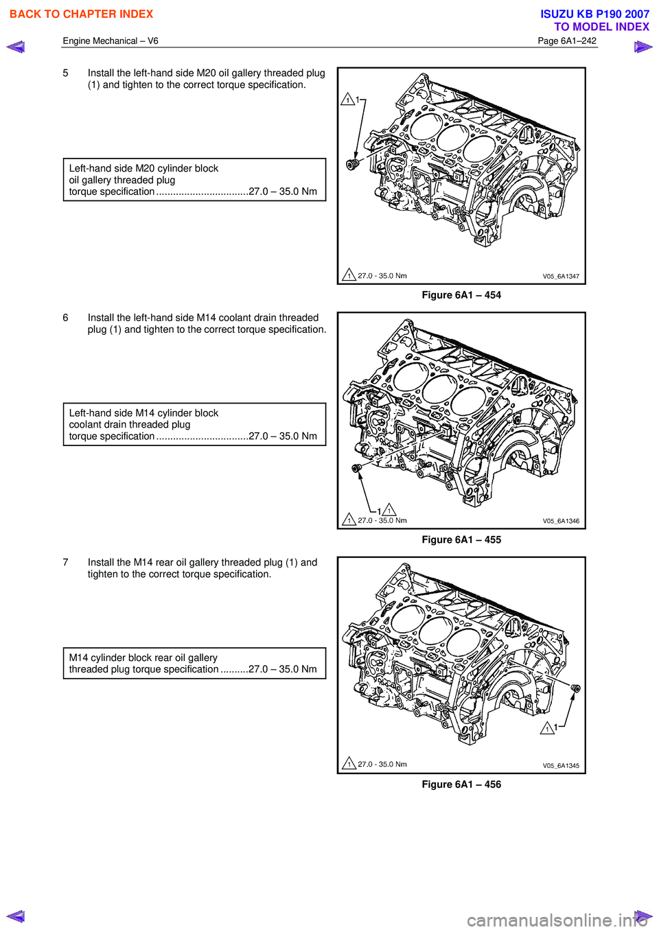
5 Install the left-hand side M20 oil gallery threaded plug
(1) and tighten to the correct torque specification.
Left-hand side M20 cylinder block
oil gallery threaded plug
torque specification .................................27.0 – 35.0 Nm
Figure 6A1 – 454
6 Install the left-hand side M14 coolant drain threaded plug (1) and tighten to the correct torque specification.
Left-hand side M14 cylinder block
coolant drain threaded plug
torque specification .................................27.0 – 35.0 Nm
Figure 6A1 – 455
7 Install the M14 rear oil gallery threaded plug (1) and tighten to the correct torque specification.
M14 cylinder block rear oil gallery
threaded plug torque specification ..........27.0 – 35.0 Nm
Figure 6A1 – 456
BACK TO CHAPTER INDEX
TO MODEL INDEX
ISUZU KB P190 2007
Page 2722 of 6020
Engine Mechanical – V6 Page 6A1–243
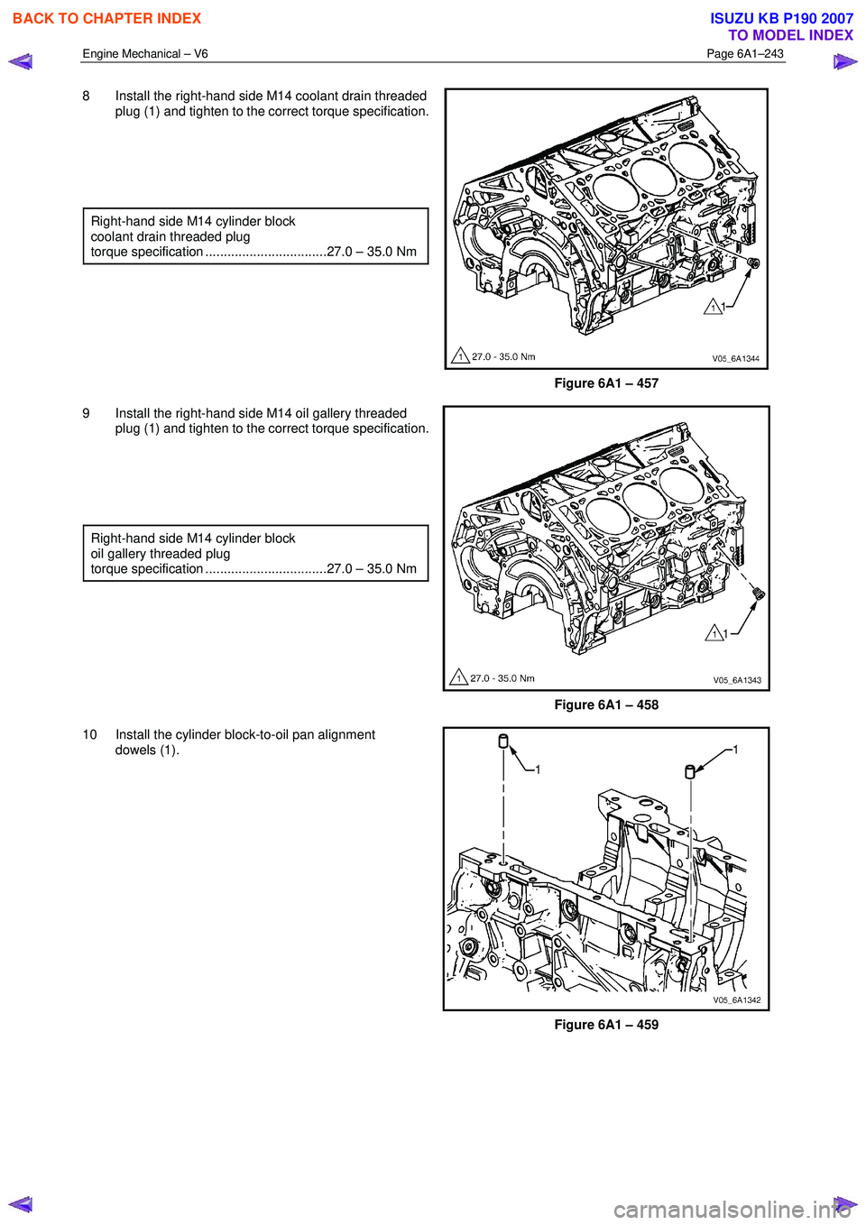
8 Install the right-hand side M14 coolant drain threaded
plug (1) and tighten to the correct torque specification.
Right-hand side M14 cylinder block
coolant drain threaded plug
torque specification .................................27.0 – 35.0 Nm
Figure 6A1 – 457
9 Install the right-hand side M14 oil gallery threaded plug (1) and tighten to the correct torque specification.
Right-hand side M14 cylinder block
oil gallery threaded plug
torque specification .................................27.0 – 35.0 Nm
Figure 6A1 – 458
10 Install the cylinder block-to-oil pan alignment dowels (1).
Figure 6A1 – 459
BACK TO CHAPTER INDEX
TO MODEL INDEX
ISUZU KB P190 2007
Page 2723 of 6020
Engine Mechanical – V6 Page 6A1–244
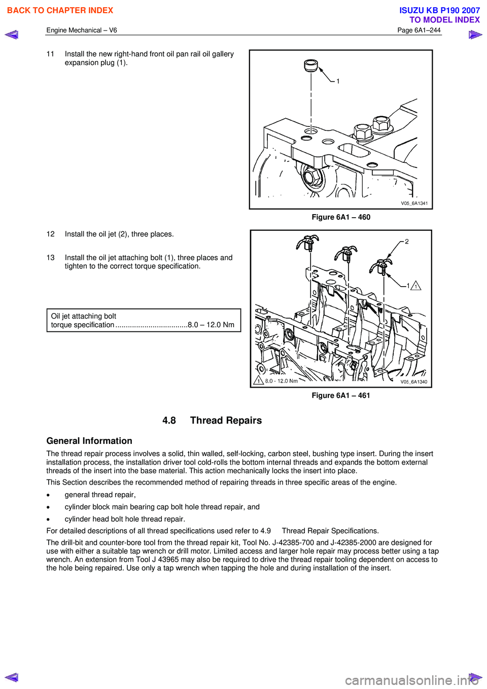
11 Install the new right-hand front oil pan rail oil gallery
expansion plug (1).
Figure 6A1 – 460
12 Install the oil jet (2), three places.
13 Install the oil jet attaching bolt (1), three places and tighten to the correct torque specification.
Oil jet attaching bolt
torque specification ...................................8.0 – 12.0 Nm
Figure 6A1 – 461
4.8 Thread Repairs
General Information
The thread repair process involves a solid, thin walled, self-locking, carbon steel, bushing type insert. During the insert
installation process, the installation driver tool cold-rolls the bottom internal threads and expands the bottom external
threads of the insert into the base material. This action mechanically locks the insert into place.
This Section describes the recommended method of repairing threads in three specific areas of the engine.
• general thread repair,
• cylinder block main bearing cap bolt hole thread repair, and
• cylinder head bolt hole thread repair.
For detailed descriptions of all thread specifications used refer to 4.9 Thread Repair Specifications.
The drill-bit and counter-bore tool from the thread repair kit, Tool No. J-42385-700 and J-42385-2000 are designed for
use with either a suitable tap wrench or drill motor. Limited access and larger hole repair may process better using a tap
wrench. An extension from Tool J 43965 may also be required to drive the thread repair tooling dependent on access to
the hole being repaired. Use only a tap wrench when tapping the hole and during installation of the insert.
BACK TO CHAPTER INDEX
TO MODEL INDEX
ISUZU KB P190 2007
Page 2771 of 6020
Engine Mechanical – V6 Page 6A1–292
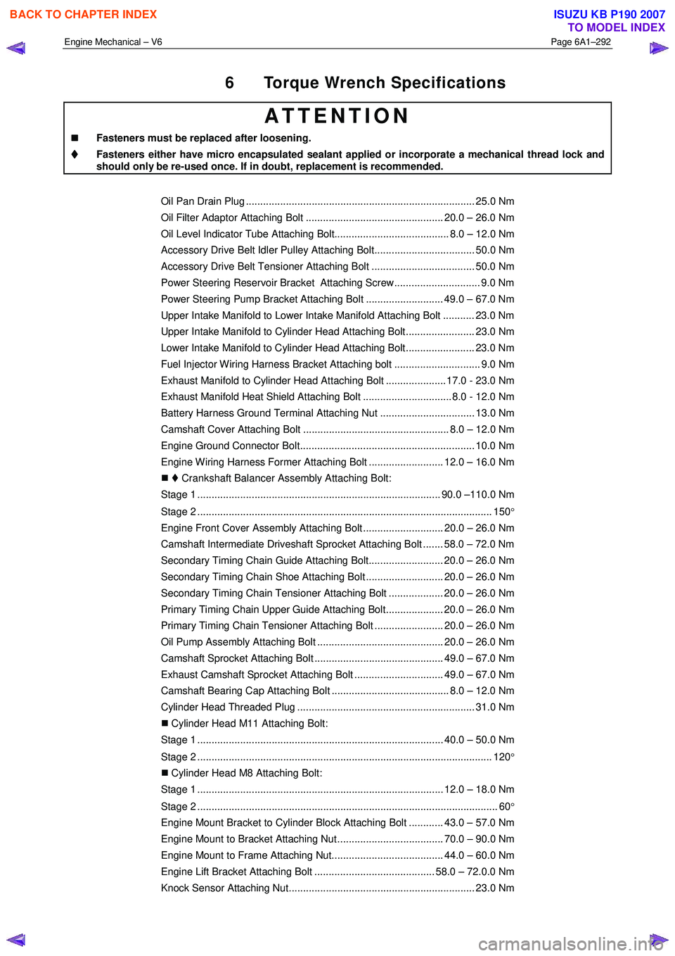
6 Torque Wrench Specifications
ATTENTION
�„
�„�„
�„
Fasteners must be replaced after loosening.
Fasteners either have micro encapsulated sealant applied or incorporate a mechanical thread lock and
should only be re-used once. If in doubt, replacement is recommended.
Oil Pan Drain Plug ................................................................................ 25.0 Nm
Oil Filter Adaptor Attaching Bolt ................................................ 20.0 – 26.0 Nm
Oil Level Indicator Tube Attaching Bolt........................................ 8.0 – 12.0 Nm
Accessory Drive Belt Idler Pulley Attaching Bolt................................... 50.0 Nm
Accessory Drive Belt Tensioner Attaching Bolt .................................... 50.0 Nm
Power Steering Reservoir Bracket Attaching Screw.............................. 9.0 Nm
Power Steering Pump Bracket Attaching Bolt ........................... 49.0 – 67.0 Nm
Upper Intake Manifold to Lower Intake Manifold Attaching Bolt ........... 23.0 Nm
Upper Intake Manifold to Cylinder Head Attaching Bolt........................ 23.0 Nm
Lower Intake Manifold to Cylinder Head Attaching Bolt........................ 23.0 Nm
Fuel Injector Wiring Harness Bracket Attaching bolt .............................. 9.0 Nm
Exhaust Manifold to Cylinder Head Attaching Bolt ..................... 17.0 - 23.0 Nm
Exhaust Manifold Heat Shield Attaching Bolt ............................... 8.0 - 12.0 Nm
Battery Harness Ground Terminal Attaching Nut ................................. 13.0 Nm
Camshaft Cover Attaching Bolt ................................................... 8.0 – 12.0 Nm
Engine Ground Connector Bolt............................................................. 10.0 Nm
Engine Wiring Harness Former Attaching Bolt .......................... 12.0 – 16.0 Nm
�„ Crankshaft Balancer Assembly Attaching Bolt:
Stage 1 ..................................................................................... 90.0 –110.0 Nm
Stage 2 ....................................................................................................... 150 °
Engine Front Cover Assembly Attaching Bolt ............................ 20.0 – 26.0 Nm
Camshaft Intermediate Driveshaft Sprocket Attaching Bolt ....... 58.0 – 72.0 Nm
Secondary Timing Chain Guide Attaching Bolt.......................... 20.0 – 26.0 Nm
Secondary Timing Chain Shoe Attaching Bolt ........................... 20.0 – 26.0 Nm
Secondary Timing Chain Tensioner Attaching Bolt ................... 20.0 – 26.0 Nm
Primary Timing Chain Upper Guide Attaching Bolt.................... 20.0 – 26.0 Nm
Primary Timing Chain Tensioner Attaching Bolt ........................ 20.0 – 26.0 Nm
Oil Pump Assembly Attaching Bolt ............................................ 20.0 – 26.0 Nm
Camshaft Sprocket Attaching Bolt ............................................. 49.0 – 67.0 Nm
Exhaust Camshaft Sprocket Attaching Bolt ............................... 49.0 – 67.0 Nm
Camshaft Bearing Cap Attaching Bolt ......................................... 8.0 – 12.0 Nm
Cylinder Head Threaded Plug .............................................................. 31.0 Nm
�„ Cylinder Head M11 Attaching Bolt:
Stage 1 ...................................................................................... 40.0 – 50.0 Nm
Stage 2 ....................................................................................................... 120 °
�„ Cylinder Head M8 Attaching Bolt:
Stage 1 ...................................................................................... 12.0 – 18.0 Nm
Stage 2 ......................................................................................................... 60 °
Engine Mount Bracket to Cylinder Block Attaching Bolt ............ 43.0 – 57.0 Nm
Engine Mount to Bracket Attaching Nut ..................................... 70.0 – 90.0 Nm
Engine Mount to Frame Attaching Nut....................................... 44.0 – 60.0 Nm
Engine Lift Bracket Attaching Bolt .......................................... 58.0 – 72.0.0 Nm
Knock Sensor Attaching Nut................................................................. 23.0 Nm
BACK TO CHAPTER INDEX
TO MODEL INDEX
ISUZU KB P190 2007
Page 2775 of 6020
Engine Mechanical – V6 Page 6A1–296
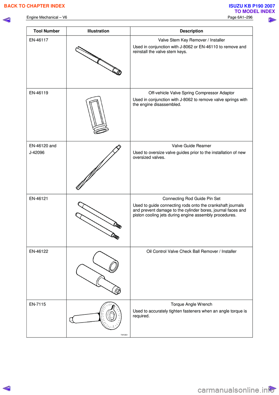
Tool Number Illustration Description
EN-46117
Valve Stem Key Remover / Installer
Used in conjunction with J-8062 or EN-46110 to remove and
reinstall the valve stem keys.
EN-46119
Off-vehicle Valve Spring Compressor Adaptor
Used in conjunction with J-8062 to remove valve springs with
the engine disassembled.
EN-46120 and
J-42096
Valve Guide Reamer
Used to oversize valve guides prior to the installation of new
oversized valves.
EN-46121
Connecting Rod Guide Pin Set
Used to guide connecting rods onto the crankshaft journals
and prevent damage to the cylinder bores, journal faces and
piston cooling jets during engine assembly procedures.
EN-46122
Oil Control Valve Check Ball Remover / Installer
EN-7115 Torque Angle W rench
Used to accurately tighten fasteners when an angle torque is
required.
BACK TO CHAPTER INDEX
TO MODEL INDEX
ISUZU KB P190 2007
Page 2778 of 6020
Engine Mechanical – V6 Page 6A1–1
Page 6A1–1
Section 6A1
Engine Mechanical – V6
ATTENTION
Before performing any service operation or other procedure described in this Section, refer to 1.1 WARNING,
CAUTION and NOTES for correct workshop practices with regard to safety and/or property damage.
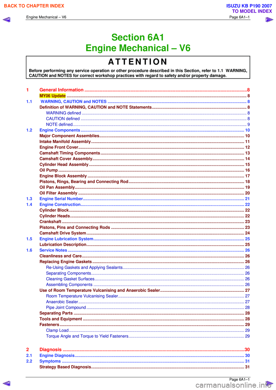
1 General Information ............................................................................................................ ...................8
MY06 Update .................................................................................................................... ......................................8
1.1 WARNING, CAUTION and NOTES .................................................................................................... ...................8
Definition of WARNING, CAUT ION and NOTE Statements ............................................................................. ....8
WARNING defined ................................................................................................................ .............................8
CAUTION defined ................................................................................................................ ..............................8
NOTE defined................................................................................................................... ..................................9
1.2 Engine Components .............................................................................................................. ..............................10
Major Component Assemblies............................................................................................................................ 10
Intake Manifold Assembly ....................................................................................................... ............................11
Engine Front Cover............................................................................................................. .................................12
Camshaft Timing Components ..................................................................................................... ......................13
Camshaft Cove r Assembly........................................................................................................ ..........................14
Cylinder Head Assembly ......................................................................................................... ............................15
Oil Pump ....................................................................................................................... ........................................16
Engine Block Assembly .......................................................................................................... ............................17
Pistons, Rings, Bearing and Connecting Rod ..................................................................................... ..............18
Oil Pan Assembly............................................................................................................... ..................................19
Oil Filter Assembly ............................................................................................................ ..................................20
1.3 Engine Serial Number........................................................................................................... ...............................21
1.4 Engine Construction............................................................................................................ ................................22
Cylinder Block ................................................................................................................. .....................................22
Cylinder Heads ..................................................................................................................................................... 22
Crankshaft ..................................................................................................................... .......................................23
Pistons, Pins and Connecting Rods .............................................................................................. ....................23
Camshaft Driv e System ....................................................................................................................................... 24
1.5 Engine Lubrication System .................................................................................................................................25
Lubrication Description........................................................................................................ ...............................25
1.6 Service Notes .................................................................................................................. .....................................26
Cleanliness and Care........................................................................................................... ................................26
Replacing Engine Gaskets .................................................................................................................................. 26
Re-Using Gaskets and Applying Sealants......................................................................................... ...............26
Separating Co mponents................................................................................................................................... 26
Cleaning Gasket Surfaces ................................................................................................................................ 26
Assembling Components ................................................................................................................................. 26
Use of Room Temperature Vulcanising and Anaerobic Sealer....................................................................... .27
Room Temperature Vu lcanising Sealer............................................................................................ ................27
Anaerobic Sealer ............................................................................................................... ...............................27
Pipe Joint Compound ............................................................................................................ ...........................28
Separating Parts ............................................................................................................... ...................................28
Tools and Equipment ............................................................................................................ ..............................28
Fasteners .............................................................................................................................................................. 29
Clamp Load ..................................................................................................................... .................................29
Torque Angle and Torque to Yield Fastener s................................................................................................... 29
2 Diagnosis ...................................................................................................................... ........................30
2.1 Engine Diagnosis ............................................................................................................... ..................................30
2.2 Symptoms ....................................................................................................................... .....................................31
Strategy Based Diagnosis................................................................................................................................... 31
BACK TO CHAPTER INDEX
TO MODEL INDEX
ISUZU KB P190 2007
Page 2784 of 6020
Engine Mechanical – V6 Page 6A1–7
Page 6A1–7
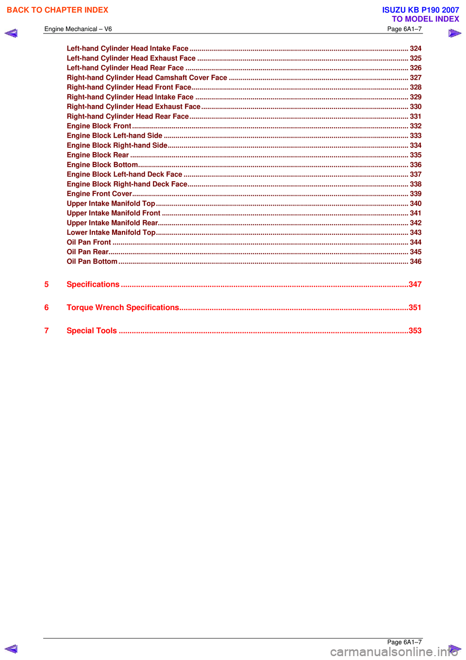
Left-hand Cylinder Head Intake Face ............................................................................................ ...................324
Left-hand Cylinder H ead Exhaust Face ........................................................................................... ................325
Left-hand Cylinder H ead Rear Face .............................................................................................. ...................326
Right-hand Cylinder Head Camshaft Cover Face ................................................................................... ........327
Right-hand Cylinder Head Front Face............................................................................................ ..................328
Right-hand Cylinder Head Intake Face ........................................................................................... .................329
Right-hand Cylinder He ad Exhaust Face .......................................................................................... ...............330
Right-hand Cylinder Head Rear Face ............................................................................................. ..................331
Engine Block Front ............................................................................................................................................ 332
Engine Block Left-hand Side .................................................................................................... ........................333
Engine Block Ri ght-hand Side ................................................................................................... .......................334
Engine Block Rear .............................................................................................................. ...............................335
Engine Block Bottom......................................................................................................................................... 336
Engine Block Left-hand Deck Face ............................................................................................... ...................337
Engine Block Righ t-hand Deck Face.............................................................................................. ..................338
Engine Front Cover............................................................................................................. ...............................339
Upper Intake Manifold Top ...................................................................................................... ..........................340
Upper Intake Mani fold Front .................................................................................................... .........................341
Upper Intake Ma nifold Rear..................................................................................................... ..........................342
Lower Intake Ma nifold Top...................................................................................................... ..........................343
Oil Pan Front .................................................................................................................. ....................................344
Oil Pan Rear........................................................................................................................................................ 345
Oil Pan Bottom ................................................................................................................................................... 346
5 Specifications .....................................................................................................................................347
6 Torque Wrench Specifications................................................................................................... .......351
7 Special Tools .................................................................................................................. ....................353
BACK TO CHAPTER INDEX
TO MODEL INDEX
ISUZU KB P190 2007