Page 2853 of 6020
Engine Mechanical – V6 Page 6A1–76
Page 6A1–76
3.8 Power Steering Pump Bracket
Remove
1 Remove the power steering pump and reservoir, refer to Section 3B Steering.
2 Remove the three bolts (1), (3) and (4) attaching t he power steering pump bracket (5) to the engine block.
3 Remove the power steering pump bracket.
Figure 6A1 – 33
Reinstall
Reinstallation of the power steering pump and pump bracket is the reverse of the removal procedure, noting the
following:
1 Hand start the bolts before tightening.
2 Tighten the bolts to the co rrect torque specification.
Power steering pump bracket
attaching bolt torque specification ......................22.0 Nm
BACK TO CHAPTER INDEX
TO MODEL INDEX
ISUZU KB P190 2007
Page 2859 of 6020

Engine Mechanical – V6 Page 6A1–82
Page 6A1–82
Reinstall
Reinstallation of the upper intake manifold and the upper and lower intake manifold assembly is the reverse of the
removal procedure, noting the following:
1 Only new gaskets are to be fitted betw een the upper and lower intake manifolds.
CAUTION
Tighten the intake manifold bolts in a circular
pattern starting at the centre bolt and moving
outward.
2 Ensure that all fasteners are tightened to the correct torque specification.
Upper intake manifold to lower
intake manifold attaching bolt
torque specificat ion ............................................ 23.0 Nm
Upper intake manifold to
cylinder head attaching bolt
torque specification ............................................ 23.0 Nm
Incorrect wiring connector installation may
cause component malfunction or component
damage.
3 Ensure all wiring connectors are fully engaged and if applicable, locked in place.
4 Ensure all wiring harnesses are correctly routed and attached securely in their retaining clips.
5 Ensure that all hoses and pipes ar e routed correctly and that any retaining clips are correctly installed.
6 Start and run the engine to c heck for correct operation.
BACK TO CHAPTER INDEX
TO MODEL INDEX
ISUZU KB P190 2007
Page 2866 of 6020

Engine Mechanical – V6 Page 6A1–89
Page 6A1–89
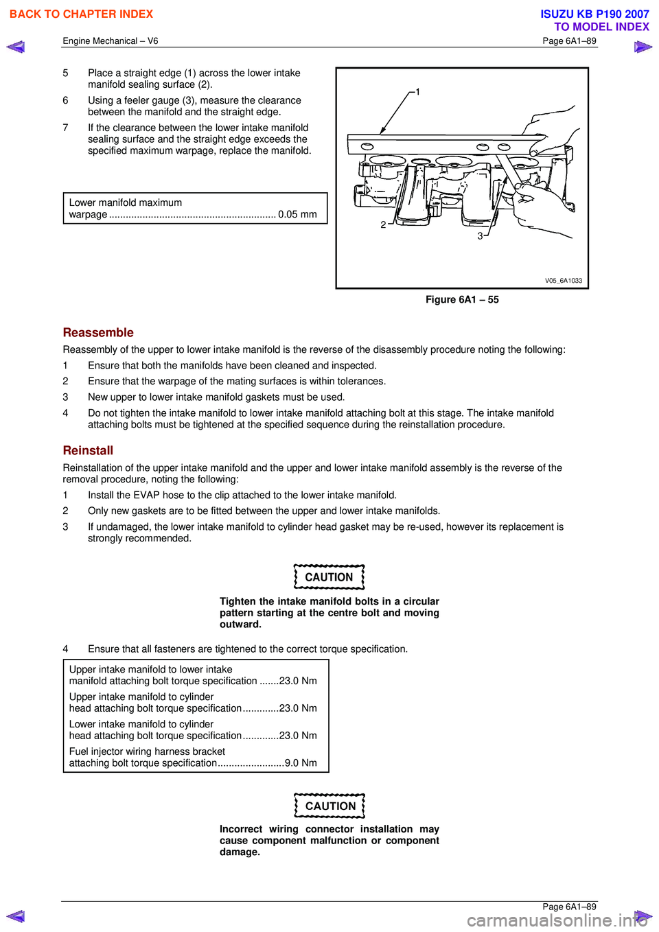
5 Place a straight edge (1) across the lower intake
manifold sealing surface (2).
6 Using a feeler gauge (3), measure the clearance
between the manifold and the straight edge.
7 If the clearance between the lower intake manifold sealing surface and the straight edge exceeds the
specified maximum warpage, replace the manifold.
Lower manifold maximum
warpage ............................................................ 0.05 mm
Figure 6A1 – 55
Reassemble
Reassembly of the upper to lower intake manifold is the reverse of the disassembly procedure noting the following:
1 Ensure that both the manifo lds have been cleaned and inspected.
2 Ensure that the warpage of the mati ng surfaces is within tolerances.
3 New upper to lower intake m anifold gaskets must be used.
4 Do not tighten the intake manifold to lower intake manifold attaching bolt at this stage. The intake manifold
attaching bolts must be tightened at the specif ied sequence during the reinstallation procedure.
Reinstall
Reinstallation of the upper intake manifold and the upper and lower intake manifo ld assembly is the reverse of the
removal procedure, noting the following:
1 Install the EVAP hose to the clip atta ched to the lower intake manifold.
2 Only new gaskets are to be fitted betw een the upper and lower intake manifolds.
3 If undamaged, the lower intake manifold to cylinder head gasket may be re-used, however its replacement is
strongly recommended.
CAUTION
Tighten the intake manifold bolts in a circular
pattern starting at the centre bolt and moving
outward.
4 Ensure that all fasteners are tightened to the correct torque specification.
Upper intake manifold to lower intake
manifold attaching bolt torq ue specification .......23.0 Nm
Upper intake manifold to cylinder
head attaching bolt torque specification .............23.0 Nm
Lower intake manifold to cylinder
head attaching bolt torque specification .............23.0 Nm
Fuel injector wiring harness bracket
attaching bolt torque specification ........................9.0 Nm
Incorrect wiring connector installation may
cause component malfunction or component
damage.
BACK TO CHAPTER INDEX
TO MODEL INDEX
ISUZU KB P190 2007
Page 2870 of 6020

Engine Mechanical – V6 Page 6A1–93
Page 6A1–93
Inspect
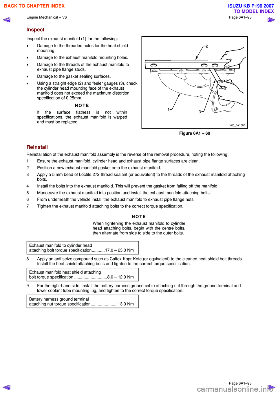
Inspect the exhaust manifold (1) for the following:
• Damage to the threaded holes for the heat shield
mounting.
• Damage to the exhaust manifold mounting holes.
• Damage to the threads of the exhaust manifold to
exhaust pipe flange studs.
• Damage to the gasket sealing surfaces.
• Using a straight edge (2) and feeler gauges (3), check
the cylinder head mounting face of the exhaust
manifold does not exceed the maximum distortion
specification of 0.25mm.
NOTE
If the surface flatness is not within
specifications, the exhaus t manifold is warped
and must be replaced.
Figure 6A1 – 60
Reinstall
Reinstallation of the exhaust manifold assembly is the reverse of the removal procedure, noting the following:
1 Ensure the exhaust manifold, cylinder head and exhaust pipe flange surfaces are clean.
2 Position a new exhaust manifold gasket onto the exhaust manifold.
3 Apply a 5 mm bead of Loctite 272 thread sealant (or equival ent) to the threads of the exhaust manifold attaching
bolts.
4 Install the bolts into the exhaust manifold. This will prevent the gasket from falling off the manifold.
5 Manoeuvre the exhaust manifold into position and install the exhaust manifold attaching bolts.
6 From underneath the vehicle install the exhaust manifold to exhaust pipe flange nuts.
7 Tighten the exhaust manifold attaching bolts to the correct torque specification.
NOTE
When tightening the exhaust manifold to cylinder
head attaching bolts, begin with the centre bolts,
then alternate from side to side to the outer bolts.
Exhaust manifold to cylinder head
attaching bolt torque spec ification ........... 17.0 – 23.0 Nm
8 Apply an anti seize compound such as Caltex Kopr-Kot e (or equivalent) to the cleaned heat shield bolt threads.
Install the heat shield attaching bolts and ti ghten to the correct torque specification.
Exhaust manifold heat shield attaching
bolt torque specificat ion ............................ 8.0 – 12.0 Nm
9 For the right-hand side, install the battery harness ground cable attaching nut through the ground terminal and
lower coolant tube mounting lug, and tighten to the correct torque specification.
Battery harness ground terminal
attaching nut torque s pecification.......................13.0 Nm
BACK TO CHAPTER INDEX
TO MODEL INDEX
ISUZU KB P190 2007
Page 2875 of 6020
Engine Mechanical – V6 Page 6A1–98
Page 6A1–98
5 Place the camshaft cover (1) into position onto the
cylinder head (2).
Figure 6A1 – 71
6 Loosely install the camshaft cover bolt (1), 13 places.
Figure 6A1 – 72
7 Tighten the camshaft cover bolts to the correct torque specification, in the sequence shown.
Camshaft cover attaching bolt
torque specificatio n ................................... 8. 0 – 12.0 Nm
Figure 6A1 – 73
BACK TO CHAPTER INDEX
TO MODEL INDEX
ISUZU KB P190 2007
Page 2876 of 6020
Engine Mechanical – V6 Page 6A1–99
Page 6A1–99
8 Remove Tool No. EN-46101 (1).
9 Tighten all remaining fasteners to the correct torque specification.
Engine ground connector bolt
torque specificat ion ............................................ 10.0 Nm
Engine wiring harness former attaching
bolt torque specification .......................... 12.0 – 16.0 Nm
Figure 6A1 – 74
BACK TO CHAPTER INDEX
TO MODEL INDEX
ISUZU KB P190 2007
Page 2879 of 6020
Engine Mechanical – V6 Page 6A1–102
Page 6A1–102
3 Using crankshaft balancer installer, Tool No.
J-41998-B (1), fully install the crankshaft balancer
assembly into the crankshaft.
CAUTION
To prevent damage to the crankshaft
threads, fully install crankshaft balancer
installer, Tool No. J-41998-B (1) into the
crankshaft before pressing the pulley and
balancer assembly.
Figure 6A1 – 79
4 Apply Loctite 272 or equivalent to the thread of a new crankshaft balancer assembly retaining bolt (1).
5 Install the crankshaft balancer assembly retaining bolt and tighten to the correct torque specification.
�„ Crankshaft balancer retaining
bolt torque specification:
Stage 1............ 90.0 – 110.0 Nm
Stage 2 ............................... 150°
Figure 6A1 – 80
BACK TO CHAPTER INDEX
TO MODEL INDEX
ISUZU KB P190 2007
Page 2886 of 6020
Engine Mechanical – V6 Page 6A1–109
Page 6A1–109
4 Place the front cover onto the special tools and slide
into position.
5 Remove the special tools from the cylinder block.
Figure 6A1 – 96
6 Hand start the front cover bolts (1).
Figure 6A1 – 97
7 Tighten the engine front cover bolts to the correct torque specification, in the sequence shown.
Engine front cover assembly attaching
bolt torque specificat ion .......................... 20.0 – 26.0 Nm
8 Fill the cooling system, refer to Section 6B1 Engine
Cooling – V6 .
9 Change the engine oil, refer to 3.1 Engine Oil.
Figure 6A1 – 98
BACK TO CHAPTER INDEX
TO MODEL INDEX
ISUZU KB P190 2007