Page 2926 of 6020

Engine Mechanical – V6 Page 6A1–149
Page 6A1–149
Primary Timing Chain Components – Excluding MY06 Update
1 If previously removed, install the left-hand secondary
timing chain components, refer to Left-hand
Secondary Timing Chain Components in this Section.
CAUTION
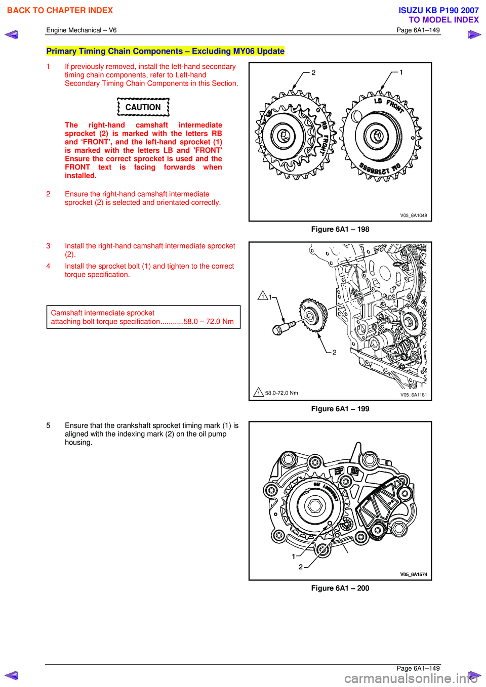
The right-hand camshaft intermediate
sprocket (2) is marked with the letters RB
and ‘FRONT’, and the left-hand sprocket (1)
is marked with the le tters LB and 'FRONT'
Ensure the correct sprocket is used and the
FRONT text is facing forwards when
installed.
2 Ensure the right-hand camshaft intermediate sprocket (2) is selected and orientated correctly.
Figure 6A1 – 198
3 Install the right-hand camshaft intermediate sprocket (2).
4 Install the sprocket bolt (1) and tighten to the correct torque specification.
Camshaft intermediate sprocket
attaching bolt torque spec ification ........... 58.0 – 72.0 Nm
Figure 6A1 – 199
5 Ensure that the crankshaft sprocket timing mark (1) is aligned with the indexing mark (2) on the oil pump
housing.
Figure 6A1 – 200
BACK TO CHAPTER INDEX
TO MODEL INDEX
ISUZU KB P190 2007
Page 2929 of 6020
Engine Mechanical – V6 Page 6A1–152
Page 6A1–152
NOTE
Do not remove the primary timing chain lower
guide (1). The primary timing chain lower guide
is not serviced separately. If the primary timing
chain lower guide must be replaced, the oil
pump assembly (2) must be replaced.
Figure 6A1 – 207
12 Ensure the primary timing chain upper guide is selected and orientated correctly.
Figure 6A1 – 208
13 Install the primary ti ming chain upper guide (1).
14 Install the primary timing chain upper guide bolts (2) and tighten to the correct torque specification.
Primary timing chain upper guide
attaching bolt torque spec ification ........... 20.0 – 26.0 Nm
Figure 6A1 – 209
BACK TO CHAPTER INDEX
TO MODEL INDEX
ISUZU KB P190 2007
Page 2932 of 6020
Engine Mechanical – V6 Page 6A1–155
Page 6A1–155
24 Verify the proper placement of the primary timing
chain tensioner gasket tab (1).
25 Tighten the primary timing c hain tensioner bolts (2) to
the correct torque specification.
Primary timing chain tensioner
attaching bolt torque spec ification ........... 20.0 – 26.0 Nm
Figure 6A1 – 216
26 Release the primary timing chain tensioner (1) by pulling out Tool No. EN 46112 (2) and unlocking the
tensioner shaft.
Figure 6A1 – 217
BACK TO CHAPTER INDEX
TO MODEL INDEX
ISUZU KB P190 2007
Page 2934 of 6020
Engine Mechanical – V6 Page 6A1–157
Page 6A1–157
3 Install the right-hand camshaft intermediate
sprocket (2).
4 Install the sprocket bolt (1) and tighten to the correct torque specification.
Camshaft intermediate sprocket
attaching bolt torque spec ification ........... 58.0 – 72.0 Nm
Figure 6A1 – 220
5 Ensure that the crankshaft sprocket timing mark (1) is aligned with the indexing mark (2) on the oil pump
housing.
Figure 6A1 – 221
6 Install the primary timing chain (1).
Figure 6A1 – 222
BACK TO CHAPTER INDEX
TO MODEL INDEX
ISUZU KB P190 2007
Page 2937 of 6020
Engine Mechanical – V6 Page 6A1–160
Page 6A1–160
NOTE
Do not remove the primary timing chain lower
guide (1). The primary timing chain lower guide
is not serviced separately. If the primary timing
chain lower guide must be replaced, the oil
pump assembly (2) must be replaced.
Figure 6A1 – 228
12 Ensure the primary timing chain upper guide is selected and orientated correctly.
Figure 6A1 – 229
13 Install the primary ti ming chain upper guide (1).
14 Install the primary timing chain upper guide bolts (2) and tighten to the correct torque specification.
Primary timing chain upper guide
attaching bolt torque spec ification ........... 20.0 – 26.0 Nm
Figure 6A1 – 230
BACK TO CHAPTER INDEX
TO MODEL INDEX
ISUZU KB P190 2007
Page 2940 of 6020
Engine Mechanical – V6 Page 6A1–163
Page 6A1–163
24 Verify the proper placement of the primary timing
chain tensioner gasket tab (1).
25 Tighten the primary timing c hain tensioner bolts (2) to
the correct torque specification.
Primary timing chain tensioner
attaching bolt torque spec ification ........... 20.0 – 26.0 Nm
Figure 6A1 – 237
26 Release the primary timing chain tensioner (1) by pulling out Tool No. EN 46112 (2) and unlocking the
tensioner shaft.
Figure 6A1 – 238
27 Verify the primary and left-hand secondary timing chain timing mark alignments (1 to 12).
Figure 6A1 – 239
28 Remove Tool No. EN 46105–1 from the left-hand cylinder head camshafts.
BACK TO CHAPTER INDEX
TO MODEL INDEX
ISUZU KB P190 2007
Page 2944 of 6020
Engine Mechanical – V6 Page 6A1–167
Page 6A1–167
CAUTION
Ensure that the right-hand secondary timing
chain guide is used when installing to the
right-hand side in this procedure.
10 Ensure that the right -hand secondary timing chain
guide is selected and orientated correctly.
Figure 6A1 – 249
11 Position the chain guide (2).
12 Install the secondary timing chain guide bolts (1) and tighten to the correct torque specification.
Secondary timing chain guide
attaching bolt torque spec ification ........... 20.0 – 26.0 Nm
Figure 6A1 – 250
BACK TO CHAPTER INDEX
TO MODEL INDEX
ISUZU KB P190 2007
Page 2945 of 6020
Engine Mechanical – V6 Page 6A1–168
Page 6A1–168
CAUTION
The right-hand secondary camshaft drive
shoe is marked with th e letters ‘RH’. Ensure
that the right-hand drive shoe is used when
installing to the right-hand side in this
procedure and that the letters ‘RH” are
facing the front of the vehicle when installed.
13 Ensure the right-hand secondary timing chain shoe is selected and orientated correctly.
Figure 6A1 – 251
14 Position the right-hand secondary timing chain shoe (1).
Figure 6A1 – 252
15 Install the secondary timing chain shoe bolt (1) and tighten to the correct torque specification.
Secondary timing chain shoe
attaching bolt torque spec ification ........... 20.0 – 26.0 Nm
Figure 6A1 – 253
BACK TO CHAPTER INDEX
TO MODEL INDEX
ISUZU KB P190 2007