Page 2948 of 6020

Engine Mechanical – V6 Page 6A1–171
Page 6A1–171
25 Verify the proper placement of the right-hand
secondary timing chain tensioner gasket tab (1).
26 Tighten the right-hand secondary timing chain tensioner bolts (2) to the co rrect torque specification.
Secondary timing chain tensioner
attaching bolt torque spec ification ........... 20.0 – 26.0 Nm
Figure 6A1 – 260
27 Release the right-hand timi ng chain tensioner (1) by
pulling out Tool No. EN 46112 (2) and unlocking the
tensioner plunger.
Figure 6A1 – 261
28 Verify all primary and secondary timing chain timing mark alignments (1 to 18).
29 Remove Tool No. EN 46105 and EN 46105-2 from the left and right-hand cylinder head camshafts.
30 Reinstall the spark plugs. Refer to Section 6C1-3
Engine Management – V6 – Service Operations.
31 Reinstall the engine front cover assembly, refer to 3.15 Front Cover Assembly .
Figure 6A1 – 262
Right-hand Secondary Timing Chain Components – MY06 Update
1 Install the primary timing chain components, refer to Primary Timing chain Components in this Section.
BACK TO CHAPTER INDEX
TO MODEL INDEX
ISUZU KB P190 2007
Page 2952 of 6020
Engine Mechanical – V6 Page 6A1–175
Page 6A1–175
CAUTION
Ensure that the right-hand secondary timing
chain guide is used when installing to the
right-hand side in this procedure.
10 Ensure that the right -hand secondary timing chain
guide is selected and orientated correctly.
Figure 6A1 – 272
11 Position the chain guide (2).
12 Install the secondary timing chain guide bolts (1) and tighten to the correct torque specification.
Secondary timing chain guide
attaching bolt torque spec ification ........... 20.0 – 26.0 Nm
Figure 6A1 – 273
13 Ensure the right-hand secondary timing chain shoe is selected and orientated correctly.
CAUTION
The right-hand secondary camshaft drive
shoe is marked with th e letters ‘RH’. Ensure
that the right-hand drive shoe is used when
installing to the right-hand side in this
procedure and that the letters ‘RH” are
facing the front of the vehicle when installed.
Figure 6A1 – 274
BACK TO CHAPTER INDEX
TO MODEL INDEX
ISUZU KB P190 2007
Page 2953 of 6020
Engine Mechanical – V6 Page 6A1–176
Page 6A1–176
14 Position the right-hand secondary timing chain shoe
(1).
Figure 6A1 – 275
15 Install the secondary timing chain shoe bolt (1) and tighten to the correct torque specification.
Secondary timing chain shoe
attaching bolt torque spec ification ........... 20.0 – 26.0 Nm
Figure 6A1 – 276
16 Ensure the right-hand secondary timing chain tensioner is selected and orientated correctly.
Figure 6A1 – 277
BACK TO CHAPTER INDEX
TO MODEL INDEX
ISUZU KB P190 2007
Page 2955 of 6020

Engine Mechanical – V6 Page 6A1–178
Page 6A1–178
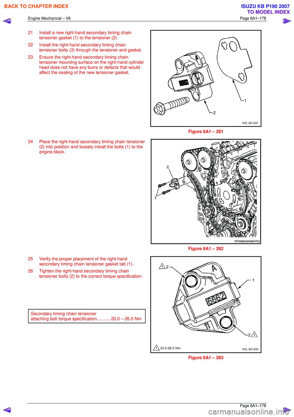
21 Install a new right-hand secondary timing chain
tensioner gasket (1) to the tensioner (2).
22 Install the right-hand secondary timing chain tensioner bolts (3) through the tensioner and gasket.
23 Ensure the right-hand secondary timing chain tensioner mounting surfac e on the right-hand cylinder
head does not have any burrs or defects that would
affect the sealing of the new tensioner gasket.
Figure 6A1 – 281
24 Place the right-hand secondar y timing chain tensioner
(2) into position and loosely install the bolts (1) to the
engine block.
Figure 6A1 – 282
25 Verify the proper plac ement of the right-hand
secondary timing chain tensioner gasket tab (1).
26 Tighten the right-hand secondary timing chain tensioner bolts (2) to the co rrect torque specification.
Secondary timing chain tensioner
attaching bolt torque spec ification ........... 20.0 – 26.0 Nm
Figure 6A1 – 283
BACK TO CHAPTER INDEX
TO MODEL INDEX
ISUZU KB P190 2007
Page 2962 of 6020
Engine Mechanical – V6 Page 6A1–185
Page 6A1–185
Reassemble
CAUTION
As there are no serviceable components
within the oil pump, a disassembled oil pump
must be replaced.
Reinstall
1 Align the oil pump gerotor with the crankshaft flats
and fit the oil pump assembly to the engine block.
2 Align the pump body (2) with the mounting holes in the cylinder block.
3 Install the oil pump bolt (1), three places, and tighten to the correct torque specification.
4 Install the primary timing chain, refer to 3.16 Timing
Chains, Tensioners, Shoes and Guides .
Oil pump attaching bolt torque
specificat ion ............................................ 20.0 – 26.0 Nm
Figure 6A1 – 297
BACK TO CHAPTER INDEX
TO MODEL INDEX
ISUZU KB P190 2007
Page 2969 of 6020
Engine Mechanical – V6 Page 6A1–192
Page 6A1–192
2 Inspect the back of each sprocket for the following:
• Sprocket damage (1),
• Camshaft locating pin damage (2) and,
• Camshaft seating/sealing inner hub flange
damage (3),
NOTE
These checks apply to both the inlet and
exhaust camshaft sprockets.
Figure 6A1 – 311
Reinstall
Reinstallation of the camshaft sprocke ts is the reverse of the removal procedure, noting the following:
1 Align the sprockets and timing chain with the marks made during removal.
2 Tighten the camshaft sprocket bolts to the correct torque specification.
Camshaft sprocket attaching
bolt torque specificat ion .......................... 49.0 – 67.0 Nm
3 Remove the timing chain retention tools.
BACK TO CHAPTER INDEX
TO MODEL INDEX
ISUZU KB P190 2007
Page 2977 of 6020
Engine Mechanical – V6 Page 6A1–200
Page 6A1–200
2 Inspect the back of each sprocket for the following:
• Sprocket damage (1),
• Camshaft locating pin damage (2) and,
• Camshaft seating/sealing inner hub flange
damage (3),
NOTE
These checks apply to both the inlet and
exhaust camshaft sprockets.
Figure 6A1 – 327
Reinstall
Reinstallation of the camshaft sprocke ts is the reverse of the removal procedure, noting the following:
1 Align the sprockets and timing chain with the marks made during removal.
2 Tighten the camshaft sprocket bolts to the correct torque specification.
Camshaft sprocket attaching
bolt torque specificat ion .......................... 49.0 – 67.0 Nm
3 Remove the timing chain retention tools.
BACK TO CHAPTER INDEX
TO MODEL INDEX
ISUZU KB P190 2007
Page 2986 of 6020

Engine Mechanical – V6 Page 6A1–209
Page 6A1–209
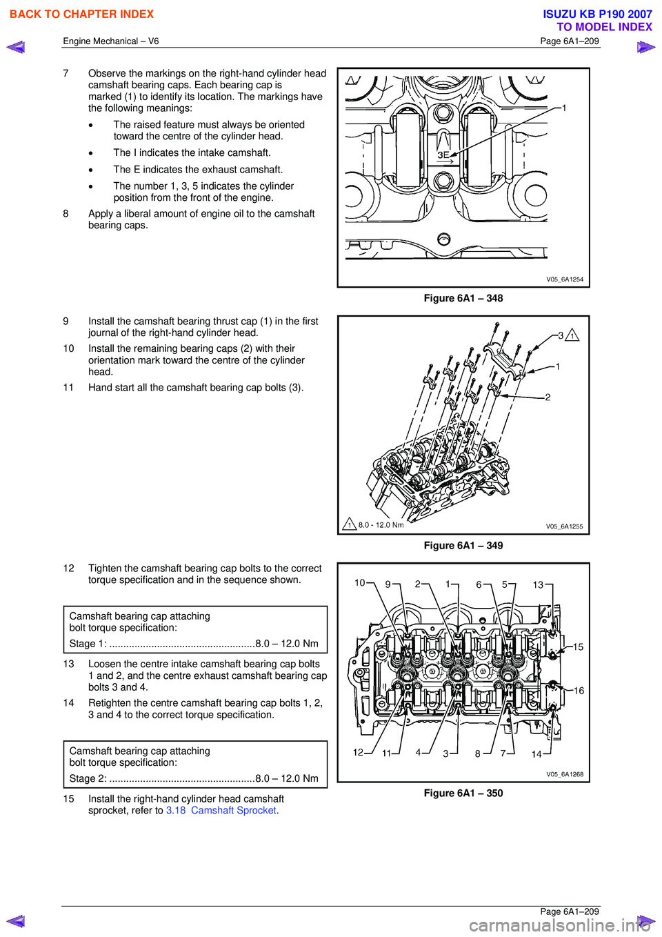
7 Observe the markings on the right-hand cylinder head
camshaft bearing caps. Each bearing cap is
marked (1) to identify its location. The markings have
the following meanings:
• The raised feature must always be oriented
toward the centre of the cylinder head.
• The I indicates the intake camshaft.
• The E indicates the exhaust camshaft.
• The number 1, 3, 5 indicates the cylinder
position from the fr ont of the engine.
8 Apply a liberal amount of engine oil to the camshaft bearing caps.
Figure 6A1 – 348
9 Install the camshaft bearing thrust cap (1) in the first journal of the right-hand cylinder head.
10 Install the remaining bearing caps (2) with their orientation mark toward t he centre of the cylinder
head.
11 Hand start all the camshaft bearing cap bolts (3).
Figure 6A1 – 349
12 Tighten the camshaft bearing cap bolts to the correct torque specification and in the sequence shown.
Camshaft bearing cap attaching
bolt torque specification:
Stage 1: .................................................... 8.0 – 12.0 Nm
13 Loosen the centre intake camshaft bearing cap bolts
1 and 2, and the centre exhaust camshaft bearing cap
bolts 3 and 4.
14 Retighten the centre camsha ft bearing cap bolts 1, 2,
3 and 4 to the correct torque specification.
Camshaft bearing cap attaching
bolt torque specification:
Stage 2: .................................................... 8.0 – 12.0 Nm
15 Install the right-hand cylinder head camshaft
sprocket, refer to 3.18 Camshaft Sprocket .
Figure 6A1 – 350
BACK TO CHAPTER INDEX
TO MODEL INDEX
ISUZU KB P190 2007