Page 2537 of 6020
Engine Mechanical – V6 Page 6A1–58
3.4 Oil Level Indicator Tube
Remove
1 Remove the oil level indicator from the oil level indicator tube.
2 Remove the bolt (2) attaching the oil level indicator tube (1) and engine wiring harness retaining bracket.
3 W ithdraw the oil level indicator tube from the oil pan.
4 Remove and discard the o-ring at the bottom of the oil level indicator tube.
Figure 6A1 – 28
Reinstall
Reinstallation of the oil level indicator tube is the reverse of the removal procedure, noting the following:
1 Install a new oil level indicator o-ring.
2 Ensure the attaching bolt passes through the engine wiring harness retaining bracket.
3 Tighten bolt to the correct torque specification.
Oil level indicator tube attaching bolt
torque specification ...................................8.0 – 12.0 Nm
BACK TO CHAPTER INDEX
TO MODEL INDEX
ISUZU KB P190 2007
Page 2539 of 6020
Engine Mechanical – V6 Page 6A1–60
NOTE
Ensure the drive belt ribs are correctly aligned
with the grooves in the accessory drive pulleys or
damage to the drive belt and accessory drive
components and pulleys may occur.
5 Reinstall the air intake duct to the air flow meter and the throttle body, refer to 6C1-3 Engine Management – V6 – Service Operations.
6 Run the engine to ensure correct operation.
3.6 Accessory Drive Belt Idler Pulley
Remove
1 Remove the accessory drive belt, refer to 3.5 Accessory Drive Belt.
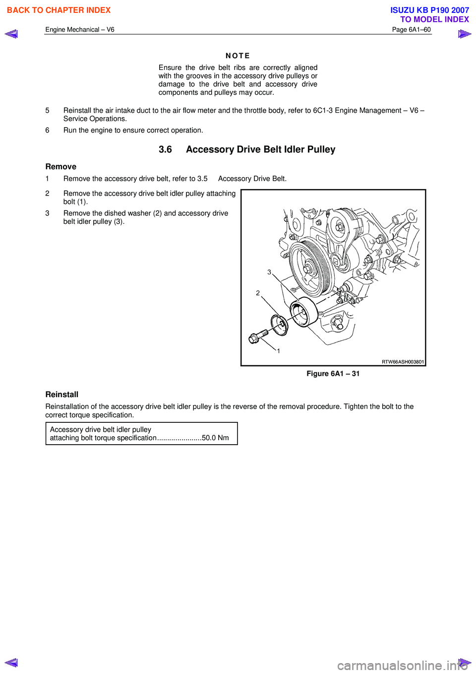
2 Remove the accessory drive belt idler pulley attaching bolt (1).
3 Remove the dished washer (2) and accessory drive belt idler pulley (3).
Figure 6A1 – 31
Reinstall
Reinstallation of the accessory drive belt idler pulley is the reverse of the removal procedure. Tighten the bolt to the
correct torque specification.
Accessory drive belt idler pulley
attaching bolt torque specification ......................50.0 Nm
BACK TO CHAPTER INDEX
TO MODEL INDEX
ISUZU KB P190 2007
Page 2540 of 6020
Engine Mechanical – V6 Page 6A1–61
3.7 Accessory Drive Belt Tensioner
Assembly
Remove
1 Remove the accessory drive belt, refer to 3.5 Accessory Drive Belt.
2 Remove the three bolts (2) attaching accessory drive belt tensioner assembly (1).
3 Remove the accessory drive belt tensioner assembly.
NOTE
The accessory drive belt tensioner pulley is not
serviced separately. If the pulley is found to be
faulty, the entire tensioner assembly must be
replaced.
Repairing a damaged accessory drive belt
pulley should not be attempted under any
circumstances.
Figure 6A1 – 32
Reinstall
Reinstallation of the accessory drive belt tensioner assembly is the reverse of the removal procedure. Tighten the bolts to
the correct torque specification.
Accessory drive belt tensioner
attaching bolt torque specification ......................50.0 Nm
BACK TO CHAPTER INDEX
TO MODEL INDEX
ISUZU KB P190 2007
Page 2541 of 6020
Engine Mechanical – V6 Page 6A1–62
3.8 Power Steering Pump Bracket
Remove
1 Remove the power steering pump and reservoir, refer to 3B_Steering.
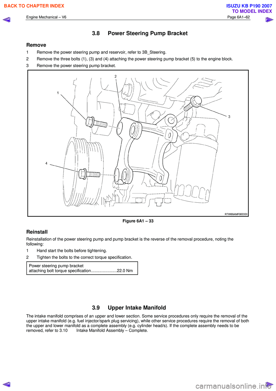
2 Remove the three bolts (1), (3) and (4) attaching the power steering pump bracket (5) to the engine block.
3 Remove the power steering pump bracket.
Figure 6A1 – 33
Reinstall
Reinstallation of the power steering pump and pump bracket is the reverse of the removal procedure, noting the
following:
1 Hand start the bolts before tightening.
2 Tighten the bolts to the correct torque specification.
Power steering pump bracket
attaching bolt torque specification ......................22.0 Nm
3.9 Upper Intake Manifold
The intake manifold comprises of an upper and lower section. Some service procedures only require the removal of the
upper intake manifold (e.g. fuel injector/spark plug servicing), while other service procedures require the removal of both
the upper and lower manifold as a complete assembly (e.g. cylinder head/s). If the complete assembly needs to be
removed, refer to 3.10 Intake Manifold Assembly – Complete.
BACK TO CHAPTER INDEX
TO MODEL INDEX
ISUZU KB P190 2007
Page 2547 of 6020
Engine Mechanical – V6 Page 6A1–68
CAUTION
Tighten the intake manifold bolts in a circular
pattern starting at the centre bolt and moving
outward.
2 Ensure that all fasteners are tightened to the correct torque specification. Upper intake manifold to lower
intake manifold attaching bolt
torque specification ............................................23.0 Nm
Upper intake manifold to
cylinder head attaching bolt
torque specification ............................................23.0 Nm
Incorrect wiring connector installation may
cause component malfunction or component
damage.
3 Ensure all wiring connectors are fully engaged and if applicable, locked in place.
4 Ensure all wiring harnesses are correctly routed and attached securely in their retaining clips.
5 Ensure that all hoses and pipes are routed correctly and that any retaining clips are correctly installed.
6 Start and run the engine to check for correct operation.
3.10 Intake Manifold Assembly – Complete
The intake manifold comprises of an upper and lower section. Some service procedures only require the removal of the
upper intake manifold (e.g. fuel injector/spark plug servicing), while other service procedures require the removal of both
the upper and lower manifold as a complete assembly (e.g. cylinder head/s). If only the upper intake manifold needs to
be removed, refer to 3.9 Upper Intake Manifold.
Remove
Disconnection of the battery affects certain
vehicle electronic systems. Refer to 1.1
WARNING, CAUTION and NOTES before
disconnecting the battery.
1 Depressurise the fuel system.
2 Disconnect the battery negative terminal.
BACK TO CHAPTER INDEX
TO MODEL INDEX
ISUZU KB P190 2007
Page 2554 of 6020
Engine Mechanical – V6 Page 6A1–75
CAUTION
Tighten the intake manifold bolts in a circular
pattern starting at the centre bolt and moving
outward.
4 Ensure that all fasteners are tightened to the correct torque specification. Upper intake manifold to lower intake
manifold attaching bolt torque specification .......23.0 Nm
Upper intake manifold to cylinder
head attaching bolt torque specification .............23.0 Nm
Lower intake manifold to cylinder
head attaching bolt torque specification .............23.0 Nm
Fuel injector wiring harness bracket
attaching bolt torque specification ........................9.0 Nm
Incorrect wiring connector installation may
cause component malfunction or component
damage.
5 Ensure all wiring connectors are fully engaged and if applicable, locked in place.
6 Ensure all wiring harnesses are correctly routed and attached securely in their retaining clips.
7 Ensure that all hoses and pipes are routed correctly and that any retaining clips are correctly installed.
8 After installation pull on any quick connect fittings to check that each is correctly installed.
9 Start and run the engine to check for correct operation.
3.11 Exhaust Manifold Assembly
Remove
Allow the engine to cool before commencing.
Disconnection of the battery affects certain
vehicle electronic systems, refer to 1.1
WARNING, CAUTION and NOTES before
disconnecting the battery.
1 Disconnect the battery negative terminal.
BACK TO CHAPTER INDEX
TO MODEL INDEX
ISUZU KB P190 2007
Page 2557 of 6020
Engine Mechanical – V6 Page 6A1–78
2 Position a new exhaust manifold gasket onto the exhaust manifold.
3 Apply a 5 mm bead of Loctite 272 thread sealant (or equivalent) to the threads of the exhaust manifold attaching bolts.
4 Install the bolts into the exhaust manifold. This will prevent the gasket from falling off the manifold.
5 Manoeuvre the exhaust manifold into position and install the exhaust manifold attaching bolts.
6 From underneath the vehicle install the exhaust manifold to exhaust pipe flange nuts.
7 Tighten the exhaust manifold attaching bolts to the correct torque specification.
NOTE
When tightening the exhaust manifold to cylinder
head attaching bolts, begin with the centre bolts,
then alternate from side to side to the outer bolts.
Exhaust manifold to cylinder head
attaching bolt torque specification ...........17.0 – 23.0 Nm
8 Apply an anti seize compound such as Caltex Kopr-Kote (or equivalent) to the cleaned heat shield bolt threads. Install the heat shield attaching bolts and tighten to the correct torque specification.
Exhaust manifold heat shield attaching
bolt torque specification ............................8.0 – 12.0 Nm
9 For the right-hand side, install the battery harness ground cable attaching nut through the ground terminal and lower coolant tube mounting lug, and tighten to the correct torque specification.
Battery harness ground terminal
attaching nut torque specification.......................13.0 Nm
BACK TO CHAPTER INDEX
TO MODEL INDEX
ISUZU KB P190 2007
Page 2562 of 6020
Engine Mechanical – V6 Page 6A1–83
5 Place the camshaft cover (1) into position onto the
cylinder head (2).
Figure 6A1 – 71
6 Loosely install the camshaft cover bolt (1), 13 places.
Figure 6A1 – 72
7 Tighten the camshaft cover bolts to the correct torque specification, in the sequence shown.
Camshaft cover attaching bolt
torque specification ...................................8.0 – 12.0 Nm
Figure 6A1 – 73
BACK TO CHAPTER INDEX
TO MODEL INDEX
ISUZU KB P190 2007