2007 ISUZU KB P190 torque
[x] Cancel search: torquePage 2436 of 6020

6E–266 ENGINE DRIVEABILITY AND EMISSIONS
MANIFOLD ABSOLUTE PRESSURE (MAP)
SENSOR
Location
Installed on the intake manifold.
Removal Procedure 1. Disconenct the negative battery cable.
2. Disconnect a MAP sensor connector from the MAP sensor.
3. Loosen a bolt and remove the MAP sensor from the intake manifold.
4. Remove the MAP sensor from the bracket.
Installation Procedure 1. Tighten the MAP sensor by a bolt with specified tightening torque.
Tightening Torque
• Bolt: 8N·m (0.8kgf·m) 2. Connect a MAP sensor connector to the MAP sensor.
3. Connect the negative battery cable.
NOTE: Verify any DTCs (diagnosis Trouble Code) are
not stored after replacement.
THROTTLE POSITION SENSOR (TPS)
Location
Installed on the throttle body.
Removal Procedure 1. Disconnect the negative battery cable.
2. Disconnect the TPS connector.
3. Loosen two screws and remove TPS from the throttle body.
Installation Procedure 1. Temporary tighten the TPS by two screws.
2. Connect a TPS connectors to the TPS.
3. Connect the Tech2 to the vehicle.
4. Connect the negative battery cable.
5. Select "Data Display" with the Tech2.
6. Check the throttle position data and adjust the TPS position.
7. Tighten two screws.
NOTE: Verify any DTCs (diagnosis Trouble Code) are
not stored after replacement.
BACK TO CHAPTER INDEX
TO MODEL INDEX
ISUZU KB P190 2007
Page 2438 of 6020
6E–268 ENGINE DRIVEABILITY AND EMISSIONS
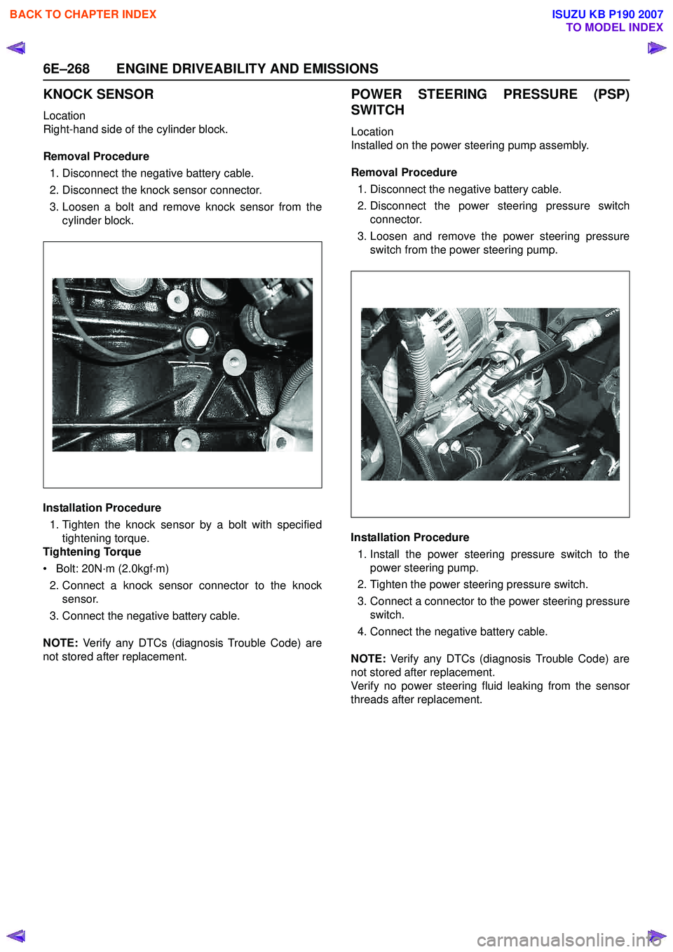
KNOCK SENSOR
Location
Right-hand side of the cylinder block.
Removal Procedure 1. Disconnect the negative battery cable.
2. Disconnect the knock sensor connector.
3. Loosen a bolt and remove knock sensor from the cylinder block.
Installation Procedure 1. Tighten the knock sensor by a bolt with specified tightening torque.
Tightening Torque
• Bolt: 20N·m (2.0kgf·m) 2. Connect a knock sensor connector to the knock sensor.
3. Connect the negative battery cable.
NOTE: Verify any DTCs (diagnosis Trouble Code) are
not stored after replacement.
POWER STEERING PRESSURE (PSP)
SWITCH
Location
Installed on the power steering pump assembly.
Removal Procedure 1. Disconnect the negative battery cable.
2. Disconnect the power steering pressure switch connector.
3. Loosen and remove the power steering pressure switch from the power steering pump.
Installation Procedure 1. Install the power steering pressure switch to the power steering pump.
2. Tighten the power steering pressure switch.
3. Connect a connector to the power steering pressure switch.
4. Connect the negative battery cable.
NOTE: Verify any DTCs (diagnosis Trouble Code) are
not stored after replacement.
Verify no power steering fluid leaking from the sensor
threads after replacement.
BACK TO CHAPTER INDEX
TO MODEL INDEX
ISUZU KB P190 2007
Page 2439 of 6020

ENGINE DRIVEABILITY AND EMISSIONS 6E–269
HEATED OXYGEN SENSOR (HO2S)
Location
Installed on the exhaust pipe.
Removal Procedure 1. Disconnect the negative battery cable.
2. Disconnect the O
2 sensor connector.
3. Loosen and remove the O
2 sensor from the exhaust
pipe.
Inspection
Inspect the louvered end of the sensor for grease, dirt,
excessive carbon build up or other contamination.
Installation Procedure
1. Install the O
2 sensor to the exhaust pipe.
2. Tighten the O
2 sensor with specified tightening
torque.
Tightening Torque
• Bolt: 42N·m (4.3kgf·m)
3. Connect a O
2 sensor connector to the O2 sensor.
4. Connect the negative battery cable.
NOTE: Verify any DTCs (diagnosis Trouble Code) are
not stored after replacement.
Verify no exhaust gas leaking from the sensor threads
after replacement.
EVAP CANISTER PURGE VALVE
SOLENOID
Location
On the intake manifold.
Removal Procedure 1. Disconenct the negative battery cable.
2. Disconnect a purge solenoid connector from the purge solenoid.
3. Disconnect two hoses from the purge solenoid valve.
4. Slide from the bracket and remove the purge solenoid.
Installation Procedure 1. Insert EVAP purge solenoid valve onto the bracket.
2. Connect two hoses to the purge solenoid valve.
3. Connect a purge solenoid connector to the purge solenoid.
4. Connect the negative battery cable.
NOTE: Verify any DTCs (diagnosis Trouble Code) are
not stored after replacement.
Verify proper connection of two hoses.
BACK TO CHAPTER INDEX
TO MODEL INDEX
ISUZU KB P190 2007
Page 2446 of 6020
6E–276 ENGINE DRIVEABILITY AND EMISSIONS
• Oil in the combustion chamber.
• The spark plug gap is not set correctly.
If spark plug fouling is excessive, check the fuel and al
system for possible causes of trouble. If fuel and al
system are normal, install spark plugs of a higher heat
range which have the same physical dimensions as the
original equipment spark plugs.
The following symptoms are characteristics of spark
plugs that are running too hot:
• Fuel mixture is too lean.
• Heat range is incorrect.
If vehicle usage does not conform to normal driving
conditions, a more suitable spark plug may be
substituted.
If fuel and al system are normal, in most cases of this
sort, the problem can be corrected by using a colder
type spark plug with the same physical dimensions as
the original equipment spark plug.
3. Check the gaskets for damage and replace if necessary.
4. Measure the spark plug gap. The specification is 1.0 to 1.1mm (0.039 to 0.043").
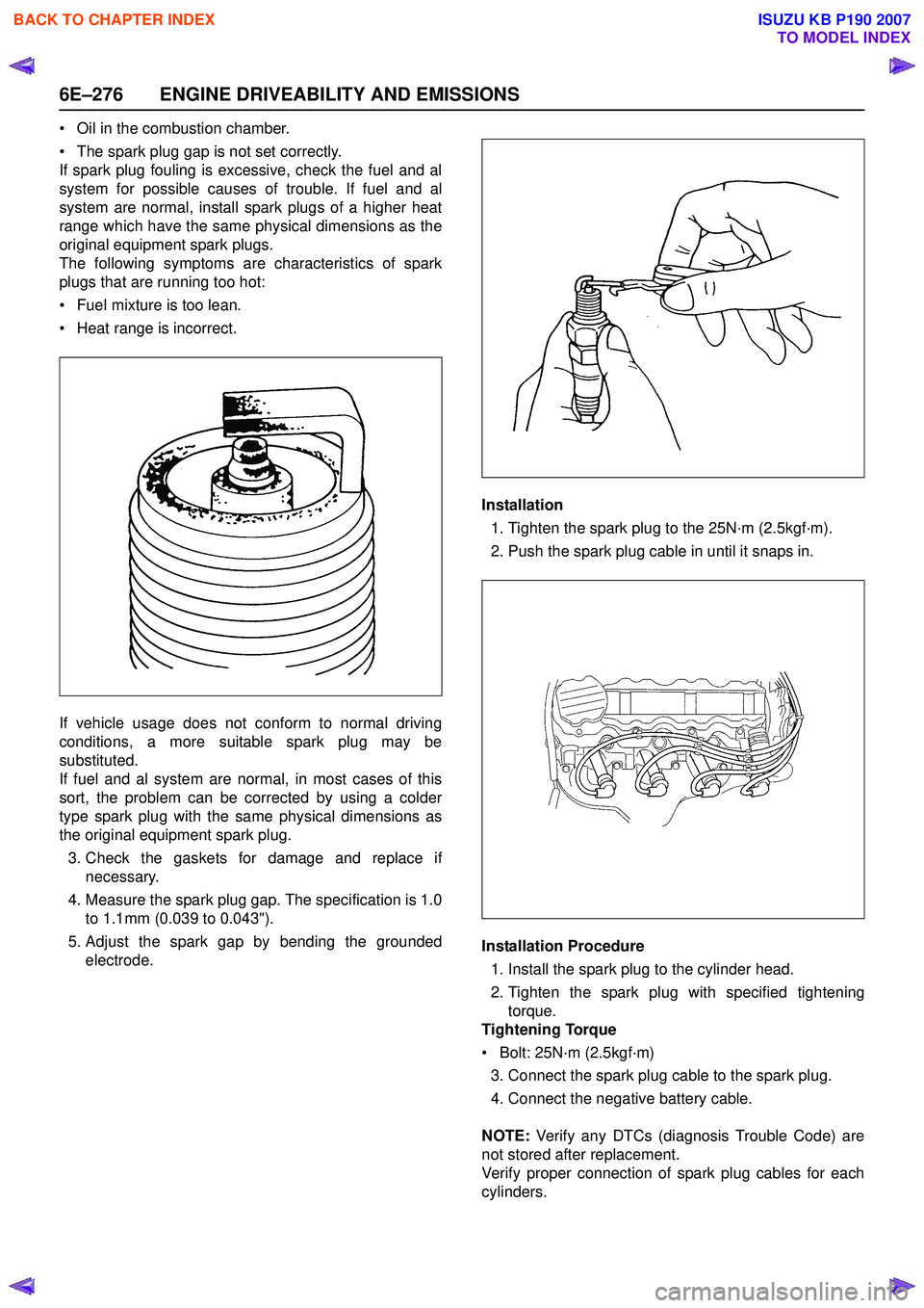
5. Adjust the spark gap by bending the grounded electrode. Installation
1. Tighten the spark plug to the 25N·m (2.5kgf·m).
2. Push the spark plug cable in until it snaps in.
Installation Procedure 1. Install the spark plug to the cylinder head.
2. Tighten the spark plug with specified tightening torque.
Tightening Torque
• Bolt: 25N·m (2.5kgf·m) 3. Connect the spark plug cable to the spark plug.
4. Connect the negative battery cable.
NOTE: Verify any DTCs (diagnosis Trouble Code) are
not stored after replacement.
Verify proper connection of spark plug cables for each
cylinders.
BACK TO CHAPTER INDEX
TO MODEL INDEX
ISUZU KB P190 2007
Page 2450 of 6020
ENGINE EXHAUST 6F-1
SECTION 6F
ENGINE EXHAUST
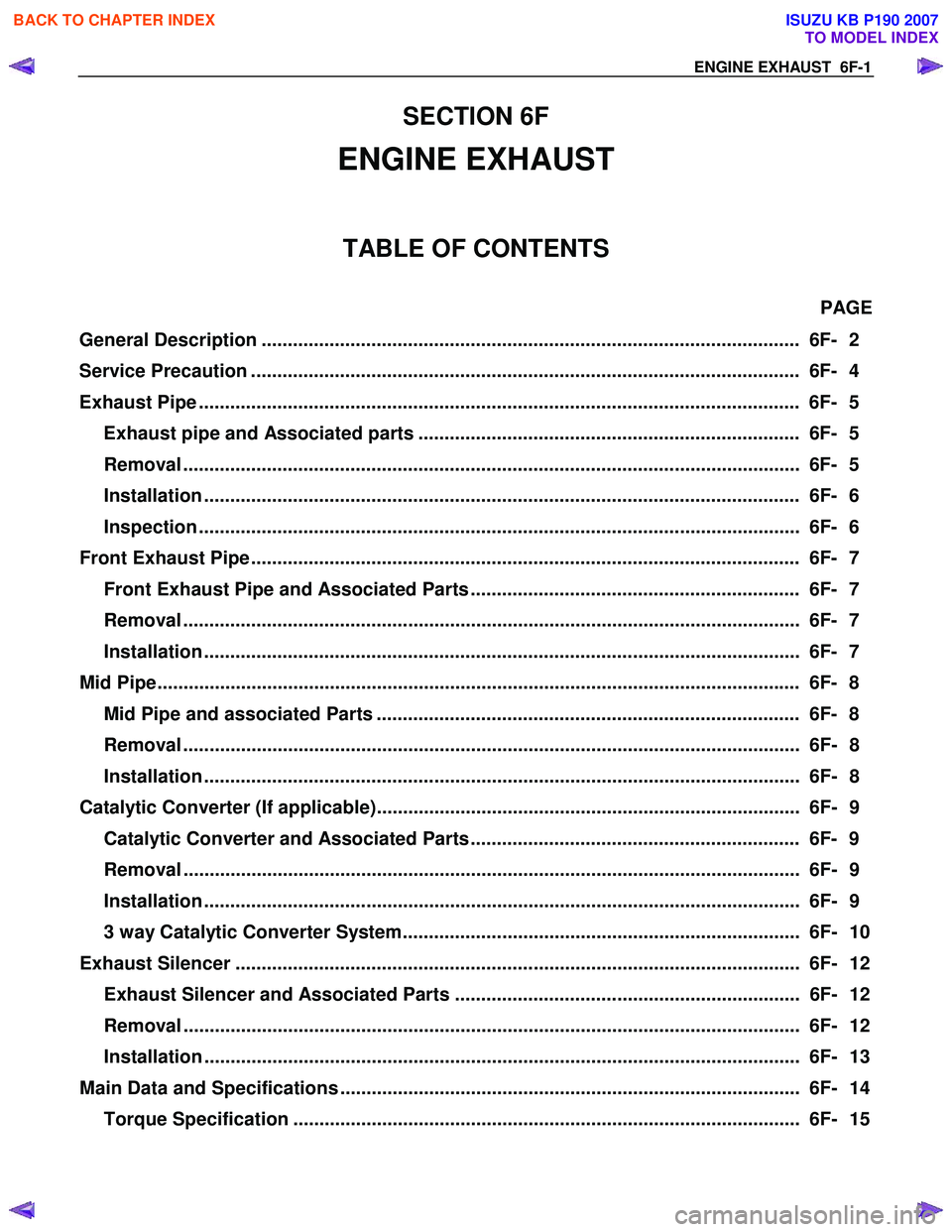
TABLE OF CONTENTS
PAGE
General Description ....................................................................................................... 6F- 2
Service Precaution ......................................................................................................... 6F- 4
Exhaust Pipe ................................................................................................................... 6F- 5
Exhaust pipe and Associated parts ......................................................................... 6F- 5
Removal ...................................................................................................................... 6F- 5
Installation .................................................................................................................. 6F- 6
Inspection ................................................................................................................... 6F- 6
Front Exhaust Pipe ......................................................................................................... 6F- 7
Front Exhaust Pipe and Associated Parts ............................................................... 6F- 7
Removal ...................................................................................................................... 6F- 7
Installation .................................................................................................................. 6F- 7
Mid Pipe....................................................................................................................... .... 6F- 8
Mid Pipe and associated Parts ................................................................................. 6F- 8
Removal ...................................................................................................................... 6F- 8
Installation .................................................................................................................. 6F- 8
Catalytic Converter (If applicable)................................................................................. 6F- 9 Catalytic Converter and Associated Parts ............................................................... 6F- 9
Removal ...................................................................................................................... 6F- 9
Installation .................................................................................................................. 6F- 9
3 way Catalytic Converter System............................................................................ 6F- 10
Exhaust Silencer ............................................................................................................ 6F- 12
Exhaust Silencer and Associated Parts .................................................................. 6F- 12
Removal ...................................................................................................................... 6F- 12
Installation .................................................................................................................. 6F- 13
Main Data and Specifications ........................................................................................ 6F- 14
Torque Specification ................................................................................................. 6F- 15
BACK TO CHAPTER INDEX
TO MODEL INDEX
ISUZU KB P190 2007
Page 2453 of 6020

6F-4 ENGINE EXHAUST
Service Precaution
CAUTION:
Always use the correct fastener in the proper location.
When you replace a fastener, use ONLY the exact part
number for that application. ISUZU will call out those
fasteners that require a replacement after removal. ISUZU
will also call out the fasteners that require thread lockers
or thread sealant. UNLESS OTHERWISE SPECIFIED, do
not use supplemental coatings (Paints, greases, or other
corrosion inhibitors) on threaded fasteners or fastener
joint interfaces. Generally, such coatings adversely affect
the fastener torque and the joint clamping force, and may
damage the fastener. When you install fasteners, use the
correct tightening sequence and specifications. Following
these instructions can help you avoid damage to parts
and systems.
BACK TO CHAPTER INDEX
TO MODEL INDEX
ISUZU KB P190 2007
Page 2455 of 6020
6F-6 ENGINE EXHAUST
Installation
To install, follow the removal steps in the reverse order.
Important - Installation
1. Front Exhaust Pipe Flange Nut
Connect the exhaust pipe to the exhaust manifold.
Front exhaust pipe to manifold nut.
Torque
N⋅m (kgf ⋅m)
28 (2.9)
Inspection
Make the necessary adjustments, and part replacements if
excessive wear or damage is discover during inspection.
1. Front Exhaust Pipe
2. Center Exhaust Pipe and Catalytic Converter Flange Nut
3. Exhaust Pipe Damper Rubber
4. Exhaust Silencer with Rear Exhaust Pipe
Check the pipes for for corrosion, cracking , damage or
misalignment and repair if required.
Check the damper rubber for deterioration or damage and
repair if required.
BACK TO CHAPTER INDEX
TO MODEL INDEX
ISUZU KB P190 2007
Page 2456 of 6020
ENGINE EXHAUST 6F-7
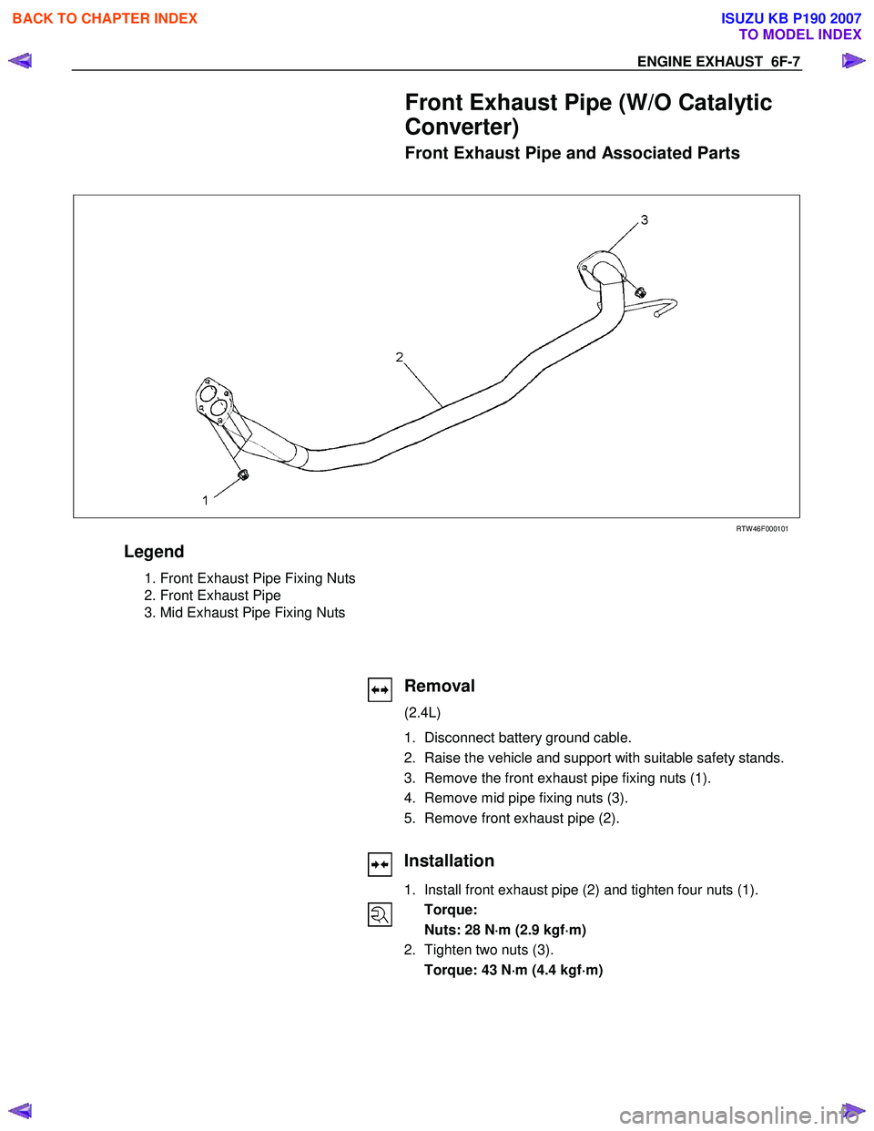
Front Exhaust Pipe (W/O Catalytic
Converter)
Front Exhaust Pipe and Associated Parts
RTW 46F000101
Legend
1. Front Exhaust Pipe Fixing Nuts
2. Front Exhaust Pipe
3. Mid Exhaust Pipe Fixing Nuts
Removal
(2.4L)
1. Disconnect battery ground cable.
2. Raise the vehicle and support with suitable safety stands.
3. Remove the front exhaust pipe fixing nuts (1).
4. Remove mid pipe fixing nuts (3).
5. Remove front exhaust pipe (2).
Installation
1. Install front exhaust pipe (2) and tighten four nuts (1). Torque:
Nuts: 28 N ⋅
⋅⋅
⋅
m (2.9 kgf ⋅
⋅⋅
⋅
m)
2. Tighten two nuts (3). Torque: 43 N ⋅
⋅⋅
⋅
m (4.4 kgf ⋅
⋅⋅
⋅
m)
BACK TO CHAPTER INDEX
TO MODEL INDEX
ISUZU KB P190 2007