2007 ISUZU KB P190 torque
[x] Cancel search: torquePage 2150 of 6020
6D3-2 STARTING AND CHARGING SYSTEM
Starting System
General Description
Cranking Circuit
The cranking system consists of a battery, starter, starter
switch, starter relay, etc. These main components are
connected.
Starter
The cranking system employs a magnetic type reduction
starter in which the motor shaft is also used as a pinion shaft.
W hen the starter switch is turned on, the contacts of magnetic
switch are closed, and the armature rotates. At the same time,
the plunger is attracted, and the pinion is pushed forward by
the shift lever to mesh with the ring gear.
Then, the ring gear runs to start the engine. W hen the engine
starts and the starter switch is turned off, the plunger returns,
the pinion is disengaged from the ring gear, and the armature
stops rotation. W hen the engine speed is higher than the
pinion, the pinion idles, so that the armature is not driven.
Service Precaution
CAUTION:
Always use the correct fastener in the proper location.
When you replace a fastener, use ONLY the exact part
number for that application. ISUZU will call out those
fasteners that require a replacement after removal. ISUZU
will also call out the fasteners that require thread lockers
or thread sealant. UNLESS OTHERWISE SPECIFIED, do
not use supplemental coatings (Paints, greases, or other
corrosion inhibitors) on threaded fasteners or fastener
joint interfaces. Generally, such coatings adversely affect
the fastener torque and the joint clamping force, and may
damage the fastener. When you install fasteners, use the
correct tightening sequence and specifications. Following
these instructions can help you avoid damage to parts
and systems.
Diagnosis
Condition Possible cause Correction
Starter does not run Charging failure Repair charging system
Battery Failure Replace Battery
Terminal connection failure Repair or replace terminal connector
and/or wiring harness
Starter switch failure Repair or replace starter switch
Starter failure Repair or replace starter
BACK TO CHAPTER INDEX
TO MODEL INDEX
ISUZU KB P190 2007
Page 2151 of 6020
STARTING AND CHARGING SYSTEM 6D3-3
Starter
Removal
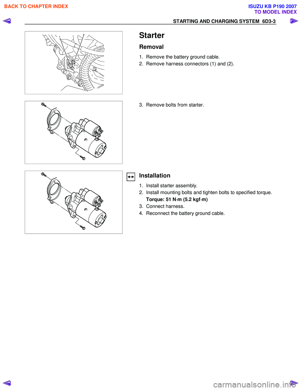
1. Remove the battery ground cable.
2. Remove harness connectors (1) and (2).
3. Remove bolts from starter.
Installation
1. Install starter assembly.
2. Install mounting bolts and tighten bolts to specified torque.
Torque: 51 N ⋅
⋅⋅
⋅
m (5.2 kgf ⋅
⋅⋅
⋅
m)
3. Connect harness.
4. Reconnect the battery ground cable.
BACK TO CHAPTER INDEX
TO MODEL INDEX
ISUZU KB P190 2007
Page 2157 of 6020
STARTING AND CHARGING SYSTEM 6D3-9
Generator Power
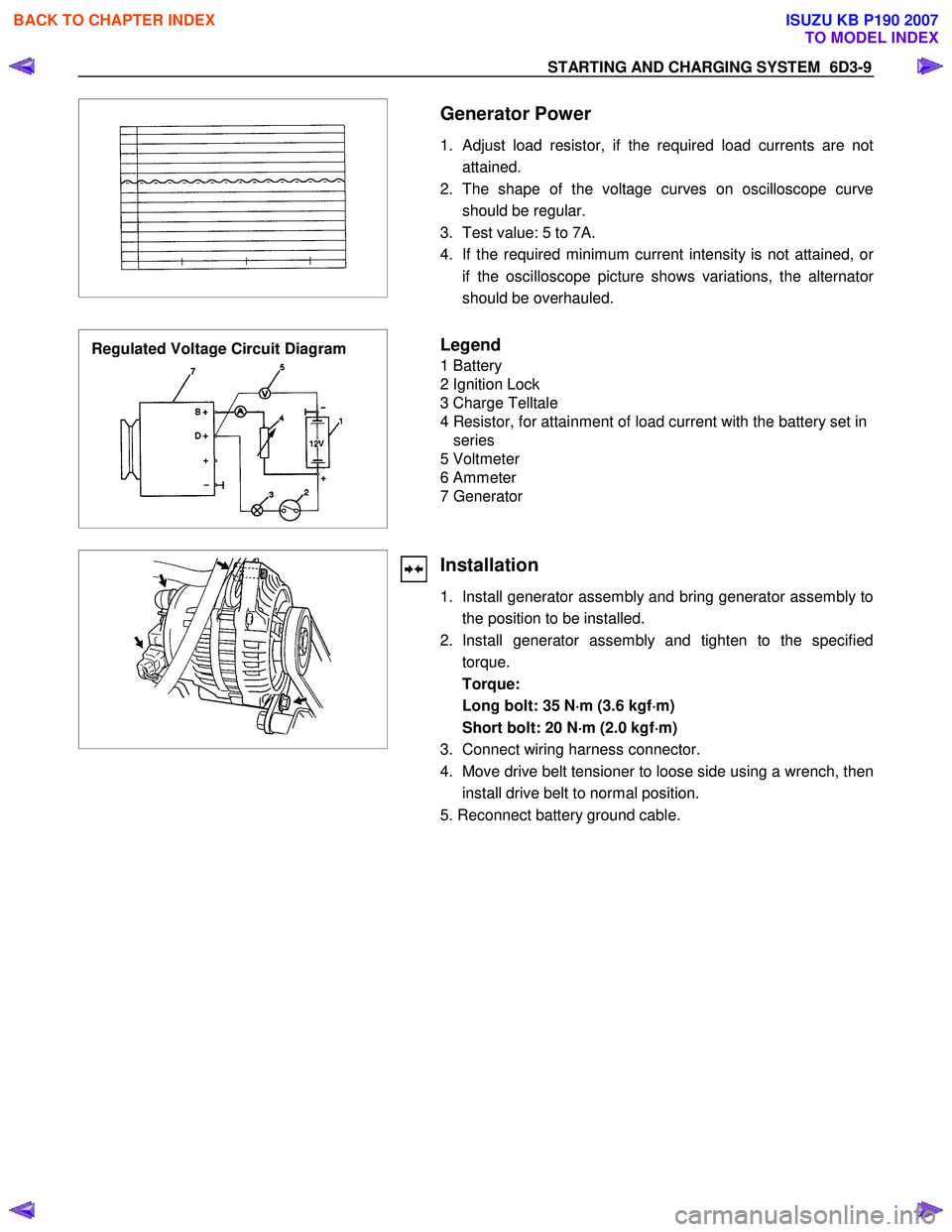
1. Adjust load resistor, if the required load currents are not attained.
2. The shape of the voltage curves on oscilloscope curve should be regular.
3. Test value: 5 to 7A.
4. If the required minimum current intensity is not attained, o
r
if the oscilloscope picture shows variations, the alternator
should be overhauled.
Regulated Voltage Circuit Diagram
Legend
1 Battery
2 Ignition Lock
3 Charge Telltale
4 Resistor, for attainment of load current with the battery set in series
5 Voltmeter
6 Ammeter
7 Generator
Installation
1. Install generator assembly and bring generator assembly to the position to be installed.
2. Install generator assembly and tighten to the specified torque.
Torque:
Long bolt: 35 N ⋅
⋅⋅
⋅
m (3.6 kgf ⋅
⋅⋅
⋅
m)
Short bolt: 20 N ⋅
⋅⋅
⋅
m (2.0 kgf ⋅
⋅⋅
⋅
m)
3. Connect wiring harness connector.
4. Move drive belt tensioner to loose side using a wrench, then install drive belt to normal position.
5. Reconnect battery ground cable.
BACK TO CHAPTER INDEX
TO MODEL INDEX
ISUZU KB P190 2007
Page 2166 of 6020
6D3-18 STARTING AND CHARGING SYSTEM
Reassembly
Generator
(a) Press new bearing onto slipring end of the rotor taking care to aplly the force to the bearing inner race only, otherwise
the bearing will be noisy and it's life will be shortened.
(b) Fit a new bearing to the drive end housing, fit the bearing plate, and four retaining screws, press the rotor into the
bearing, using a support tool to take the thrust against the
bearing inner.
The support is fitted from the pulley side of the bearing. In this way the thrust is not taken by the drive end housing.
(c) To fit pulley, mount an 8mm Allen key in the vice with the short end upwards, place a 24mm ring spanner on the shaft
nut, position the internal hexagon of the rotor shaft onto the
Allen key, tighten the nut to the required torque(See torque
chart)
(d) Inspect the bearing support ring for signs of damage, if in doubt replace the ring by pressing it into the housing b
y
hand, do not use excessive force.
(e) To refit the rectifier, fit new mica washers to the positive heatsink B+ bolt and retaining screw each washer must
have heatsink compound applied to both surfaces before
fitting.
Fit the three retaining screws to the rectifier then install into slipring end housing. Tighten the B+ bolt to the reuired
torque.
(f) To refit the stator, make sure the spigot surface are clean and free from damage, fit the stator into the slipring end
housing noting the correct lead connection positioning. Fit
the stator leads into the wire loops in the recrifier. Using a
pair of pliers squeeze the loop to retain the stator lead prior
to soldering. Repeat for each lead in turn, solder the leads
into position using 60/40 resin cored solder. Make sure the
leads will be clear of the internal fan when the rotor is
assmebled into the stator.
(g) Carefully install the rotor into the stator/slipring end housing assembly, noting the alignment of the housings and through
bolt holes. Fit the through bolts making sure the stator is
seated correctly, tighten the through bolts to the correct
torque setting (uneven torque can produce magnetic noise
levels above normal).
(h) Fitting the regulator. Compress the brushes into the brush holder by hand, slip the regulator through the opening in the
rear of the slipring end housing until the brushes come in
contact with the slipring. Press the regulator towards the
slipring until the holes are aligned then fit the retaining
screws and tighten.
BACK TO CHAPTER INDEX
TO MODEL INDEX
ISUZU KB P190 2007
Page 2169 of 6020
STARTING AND CHARGING SYSTEM 6D3-21
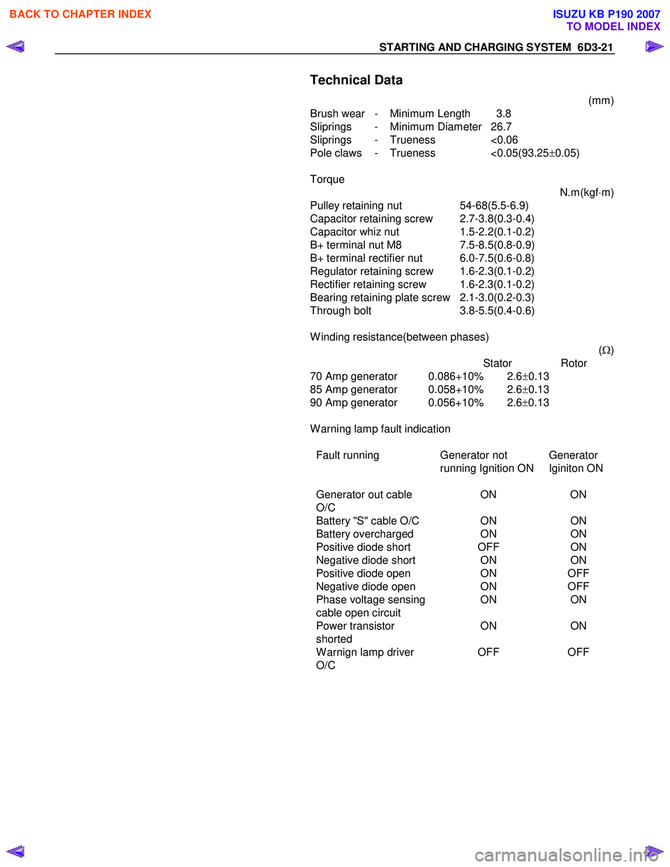
Technical Data
(mm)
Brush wear - Minimum Length 3.8
Sliprings - Minimum Diameter 26.7
Sliprings - Trueness <0.06
Pole claws - Trueness <0.05(93.25 ±0.05)
Torque N.m(kgf⋅m)
Pulley retaining nut 54-68(5.5-6.9)
Capacitor retaining screw 2.7-3.8(0.3-0.4)
Capacitor whiz nut 1.5-2.2(0.1-0.2)
B+ terminal nut M8 7.5-8.5(0.8-0.9)
B+ terminal rectifier nut 6.0-7.5(0.6-0.8)
Regulator retaining screw 1.6-2.3(0.1-0.2)
Rectifier retaining screw 1.6-2.3(0.1-0.2)
Bearing retaining plate screw 2.1-3.0(0.2-0.3)
Through bolt 3.8-5.5(0.4-0.6)
W inding resistance(between phases) (Ω )
Stator Rotor
70 Amp generator 0.086+10% 2.6 ±0.13
85 Amp generator 0.058+10% 2.6 ±0.13
90 Amp generator 0.056+10% 2.6 ±0.13
W arning lamp fault indication
Fault running Generator not
running Ignition ON Generator
Iginiton ON
Generator out cable
O/C ON
ON
Battery "S" cable O/C ONON
Battery overcharged ONON
Positive diode short OFFON
Negative diode short ONON
Positive diode open ONOFF
Negative diode open ONOFF
Phase voltage sensing ONON
cable open circuit
Power transistor
shorted ON
ON
W arnign lamp driver
O/C OFF
OFF
BACK TO CHAPTER INDEX
TO MODEL INDEX
ISUZU KB P190 2007
Page 2225 of 6020
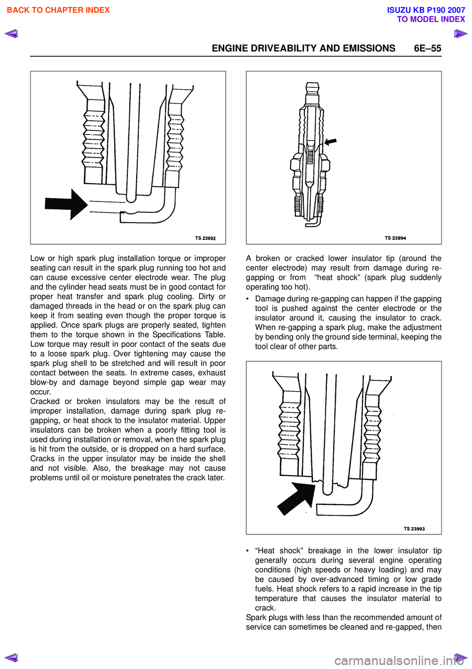
ENGINE DRIVEABILITY AND EMISSIONS 6E–55
Low or high spark plug installation torque or improper
seating can result in the spark plug running too hot and
can cause excessive center electrode wear. The plug
and the cylinder head seats must be in good contact for
proper heat transfer and spark plug cooling. Dirty or
damaged threads in the head or on the spark plug can
keep it from seating even though the proper torque is
applied. Once spark plugs are properly seated, tighten
them to the torque shown in the Specifications Table.
Low torque may result in poor contact of the seats due
to a loose spark plug. Over tightening may cause the
spark plug shell to be stretched and will result in poor
contact between the seats. In extreme cases, exhaust
blow-by and damage beyond simple gap wear may
occur.
Cracked or broken insulators may be the result of
improper installation, damage during spark plug re-
gapping, or heat shock to the insulator material. Upper
insulators can be broken when a poorly fitting tool is
used during installation or removal, when the spark plug
is hit from the outside, or is dropped on a hard surface.
Cracks in the upper insulator may be inside the shell
and not visible. Also, the breakage may not cause
problems until oil or moisture penetrates the crack later. A broken or cracked lower insulator tip (around the
center electrode) may result from damage during re-
gapping or from “heat shock” (spark plug suddenly
operating too hot).
• Damage during re-gapping can happen if the gapping tool is pushed against the center electrode or the
insulator around it, causing the insulator to crack.
When re-gapping a spark plug, make the adjustment
by bending only the ground side terminal, keeping the
tool clear of other parts.
• “Heat shock” breakage in the lower insulator tip generally occurs during several engine operating
conditions (high speeds or heavy loading) and may
be caused by over-advanced timing or low grade
fuels. Heat shock refers to a rapid increase in the tip
temperature that causes the insulator material to
crack.
Spark plugs with less than the recommended amount of
service can sometimes be cleaned and re-gapped, then
BACK TO CHAPTER INDEX
TO MODEL INDEX
ISUZU KB P190 2007
Page 2434 of 6020
6E–264 ENGINE DRIVEABILITY AND EMISSIONS
ON-VEHICLE SERVICE PROCEDURE
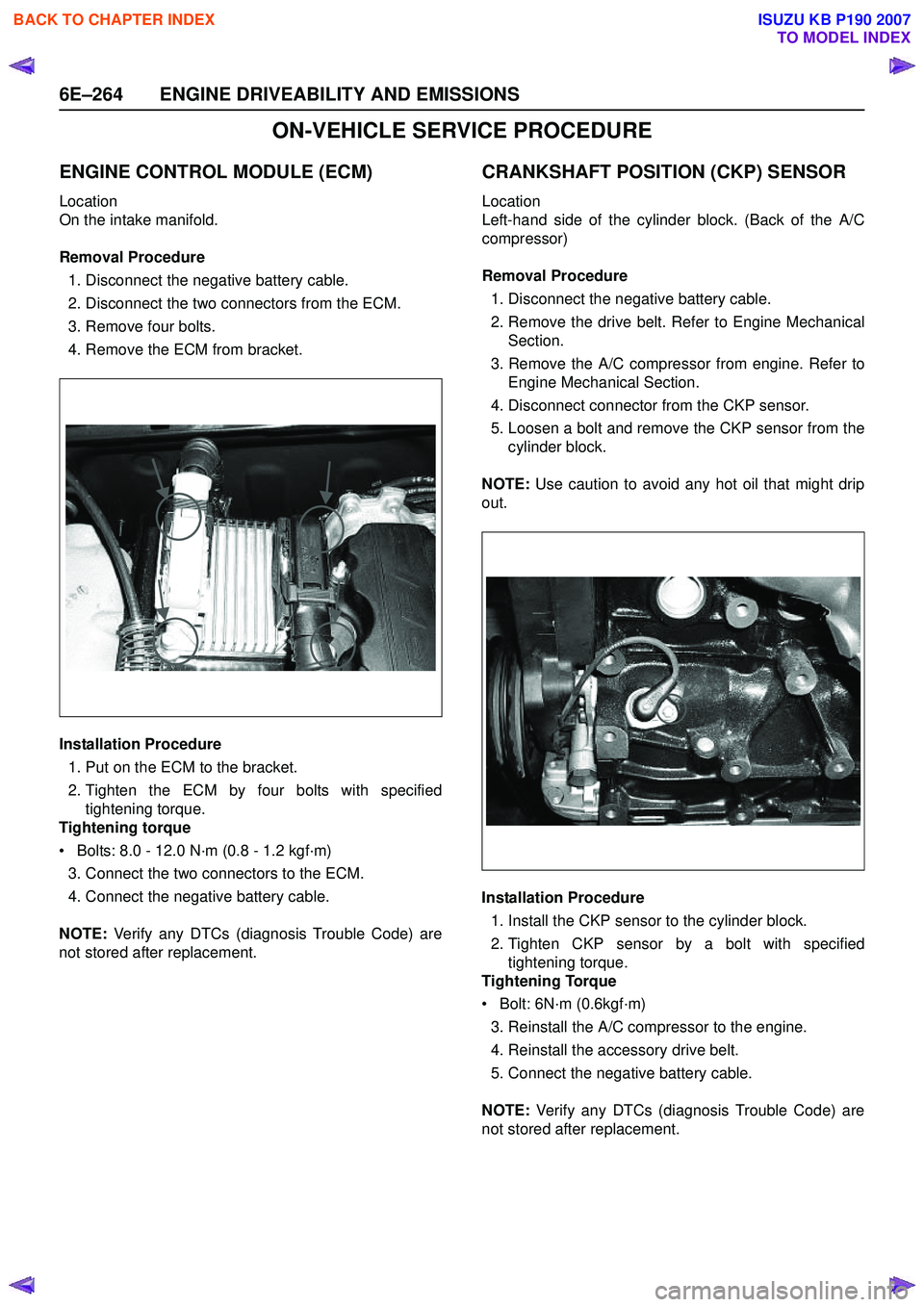
ENGINE CONTROL MODULE (ECM)
Location
On the intake manifold.
Removal Procedure 1. Disconnect the negative battery cable.
2. Disconnect the two connectors from the ECM.
3. Remove four bolts.
4. Remove the ECM from bracket.
Installation Procedure 1. Put on the ECM to the bracket.
2. Tighten the ECM by four bolts with specified tightening torque.
Tightening torque
• Bolts: 8.0 - 12.0 N·m (0.8 - 1.2 kgf·m) 3. Connect the two connectors to the ECM.
4. Connect the negative battery cable.
NOTE: Verify any DTCs (diagnosis Trouble Code) are
not stored after replacement.
CRANKSHAFT POSITION (CKP) SENSOR
Location
Left-hand side of the cylinder block. (Back of the A/C
compressor)
Removal Procedure 1. Disconnect the negative battery cable.
2. Remove the drive belt. Refer to Engine Mechanical Section.
3. Remove the A/C compressor from engine. Refer to Engine Mechanical Section.
4. Disconnect connector from the CKP sensor.
5. Loosen a bolt and remove the CKP sensor from the cylinder block.
NOTE: Use caution to avoid any hot oil that might drip
out.
Installation Procedure 1. Install the CKP sensor to the cylinder block.
2. Tighten CKP sensor by a bolt with specified tightening torque.
Tightening Torque
• Bolt: 6N·m (0.6kgf·m)
3. Reinstall the A/C compressor to the engine.
4. Reinstall the accessory drive belt.
5. Connect the negative battery cable.
NOTE: Verify any DTCs (diagnosis Trouble Code) are
not stored after replacement.
BACK TO CHAPTER INDEX
TO MODEL INDEX
ISUZU KB P190 2007
Page 2435 of 6020
ENGINE DRIVEABILITY AND EMISSIONS 6E–265
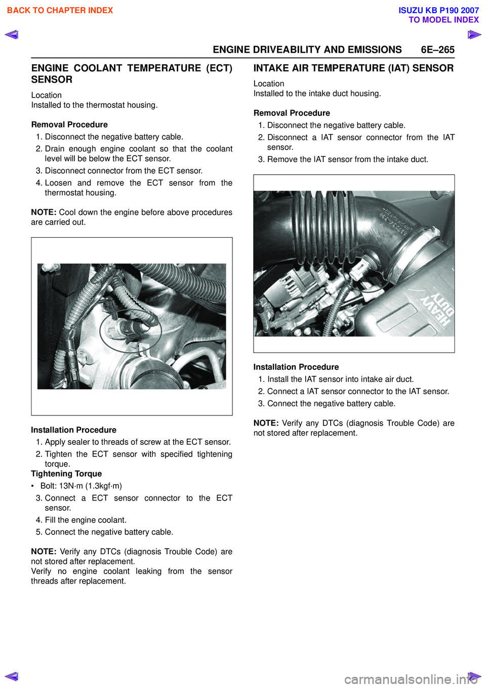
ENGINE COOLANT TEMPERATURE (ECT)
SENSOR
Location
Installed to the thermostat housing.
Removal Procedure 1. Disconnect the negative battery cable.
2. Drain enough engine coolant so that the coolant level will be below the ECT sensor.
3. Disconnect connector from the ECT sensor.
4. Loosen and remove the ECT sensor from the thermostat housing.
NOTE: Cool down the engine before above procedures
are carried out.
Installation Procedure
1. Apply sealer to threads of screw at the ECT sensor.
2. Tighten the ECT sensor with specified tightening torque.
Tightening Torque
• Bolt: 13N·m (1.3kgf·m)
3. Connect a ECT sensor connector to the ECT sensor.
4. Fill the engine coolant.
5. Connect the negative battery cable.
NOTE: Verify any DTCs (diagnosis Trouble Code) are
not stored after replacement.
Verify no engine coolant leaking from the sensor
threads after replacement.
INTAKE AIR TEMPERATURE (IAT) SENSOR
Location
Installed to the intake duct housing.
Removal Procedure 1. Disconnect the negative battery cable.
2. Disconnect a IAT sensor connector from the IAT sensor.
3. Remove the IAT sensor from the intake duct.
Installation Procedure 1. Install the IAT sensor into intake air duct.
2. Connect a IAT sensor connector to the IAT sensor.
3. Connect the negative battery cable.
NOTE: Verify any DTCs (diagnosis Trouble Code) are
not stored after replacement.
BACK TO CHAPTER INDEX
TO MODEL INDEX
ISUZU KB P190 2007