Page 5106 of 6020
8A-168 ELECTRICAL-BODY AND CHASSIS
HALOGEN HEADLIGHT BULB (B type)
Removal
1. Open the bonnet.
2. Disconnect the headlight bulb connectors.
RTW 580SH000101
3. Turn the bulb counterclockwise to remove it.
Installation
To install the headlight, follow the removal procedure in
reverse order.
Pay close attention to the important points mentioned in the
following paragraphs.
Connector
Be absolutely sure that the headlight connector is securely
connected.
This will prevent a contact and an open circuit.
BACK TO CHAPTER INDEX TO MODEL INDEXISUZU KB P190 2007
Page 5108 of 6020
8A-170 ELECTRICAL-BODY AND CHASSIS
FRONT TURN SIGNAL LIGHT BULB
(A type)
Removal
HALOGEN STD TYPE RTW 78ASH000201
1. Turn the socket counterclockwise to disconnect it from the
front turn signal light housing.
2. Turn the bulb
1 counterclockwise to remove it.
1
HALOGEN PROJECTOR TYPE RTW 78ASH001001
FRONT COMBINATION LIGHT
ASSEMBLY (B type)
Removal
1. Open the bonnet.
RTW 580SH000901
2. Remove the bolt of front combination light assembly
3. Disconnect the front combination light harness connector.
4. Remove the front combination light assembly.
Installation
To install the front combination light assembly follow the
removal procedure in the reverse order.
Connector
Be absolutely sure that the front combination light harness
connector is correctly installed.
This will prevent a poor contact and an open circuit.
BACK TO CHAPTER INDEX TO MODEL INDEXISUZU KB P190 2007
Page 5109 of 6020
ELECTRICAL-BODY AND CHASSIS 8A-171
FRONT TURN SIGNAL LIGHT BULB
Removal
RTW 580SH000201
1. Remove the front combination light assembly.
• Refer to “FRONT COMBINATION LIGHT ASSEMBLY”
removal procedure in this section.
2. Turn the bulb counterclockwise to remove it. (Gray socket side)
Installation
Follow the removal procedure in the reverse order to install the
front turn signal light.
Pay close attention to the important points mentioned in the
following paragraphs.
Connector
Be absolutely sure that the clearance light connector is
securely connected.
This will prevent a poor contact and an open circuit.
CLEARANCE LIGHT BULB (A type)
Removal
HALOGEN STD TYPE RTW 78ASH000301
1. Turn the socket counterclockwise to disconnect it from the
clearance light housing.
2. Turn the bulb
1 counterclockwise to remove it.
1 HALOGEN PROJECTOR TYPE RTW 78ASH001101
BACK TO CHAPTER INDEX
TO MODEL INDEXISUZU KB P190 2007
Page 5110 of 6020

8A-172 ELECTRICAL-BODY AND CHASSIS
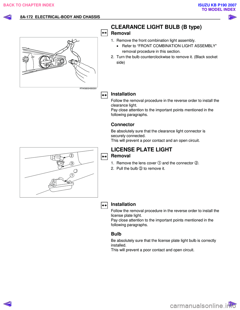
CLEARANCE LIGHT BULB (B type)
Removal
RTW 580SH000301
1. Remove the front combination light assembly.
• Refer to “FRONT COMBINATION LIGHT ASSEMBLY”
removal procedure in this section.
2. Turn the bulb counterclockwise to remove it. (Black socket side)
Installation
Follow the removal procedure in the reverse order to install the
clearance light.
Pay close attention to the important points mentioned in the
following paragraphs.
Connector
Be absolutely sure that the clearance light connector is
securely connected.
This will prevent a poor contact and an open circuit.
LICENSE PLATE LIGHT
Removal
1. Remove the lens cover 1 and the connector 2.
2. Pull the bulb
3 to remove it.
Installation
Follow the removal procedure in the reverse order to install the
license plate light.
Pay close attention to the important points mentioned in the
following paragraphs.
Bulb
Be absolutely sure that the license plate light bulb is correctly
installed.
This will prevent a poor contact and open circuit.
BACK TO CHAPTER INDEX TO MODEL INDEXISUZU KB P190 2007
Page 5115 of 6020
ELECTRICAL-BODY AND CHASSIS 8A-177
HEADLIGHT ADJUSTMENT
Preparation
Place the vehicle with 1 person in driver seat on a level surface
and check to see if the inflation pressure of the tires is correct,
the lenses are clean, the battery is sufficiently charged, and
adjust to place vehicle by using the screen.
1. Set a vertical screen on a level surface.
2. Toward the screen
1from the bulb center mark of the
headlight, extend parallel lines to the floor. Mark point
A
and B on the screen at the intersection of parallel line and
the screen.
3. Draw vertical lines through point
A and B on the screen.
4. Keep the vehicle 2 1m apart from the screen 1.
5. Draw a horizontal line through point
A and Bon the screen
1.
6. Turn the headlight low beam on.
7. Adjust the CUTLINE 11.6 mm below the horizontal line
H.
8. Adjust the BENDING POINT to the vertical line
V.
NOTE:
Always adjust vertical adjustment first.
BACK TO CHAPTER INDEX TO MODEL INDEXISUZU KB P190 2007
Page 5117 of 6020
ELECTRICAL-BODY AND CHASSIS 8A-179
RTW 78ASH002901
LIGHTING RELAY, TAIL RELAY
Check continuity between the relay terminals.
2 - 1............................ No continuity
(W hen battery voltage is applied between 3 and 4)
2 - 1............................ Continuity
GLOVE BOX ILLUMINATION
Removal
1. Remove the bulb cover 1.
2. Remove the bulb
2.
Installation
To install, follow the removal steps in the reverse order.
POWER/3rd START SW
Removal
• Refer to the “Front consol” Section 10 of this manual.
1. Disconnect the battery ground cable.
2. Remove the power/3rd start switch.
3. Remove the bulb.
Installation
To install, follow the removal steps in the reverse order.
A/T LEVER LIGHT BULB
Removal
• Refer to the “Front consol” Section 10 of this manual.
1. Remove the A/T lever cover.
2. Remove the light bulb
1.
Installation
To install, follow the removal steps in the reverse order.
BACK TO CHAPTER INDEX TO MODEL INDEXISUZU KB P190 2007
Page 5125 of 6020

ELECTRICAL-BODY AND CHASSIS 8A-187
RTW 780SH000601
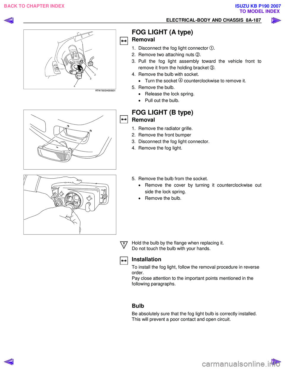
FOG LIGHT (A type)
Removal
1. Disconnect the fog light connector 1 .
2. Remove two attaching nuts
2.
3. Pull the fog light assembly toward the vehicle front to remove it from the holding bracket
3 .
4. Remove the bulb with socket. • Turn the socket
4 counterclockwise to remove it.
5. Remove the bulb. • Release the lock spring.
• Pull out the bulb.
FOG LIGHT (B type)
Removal
1. Remove the radiator grille.
2. Remove the front bumper
3. Disconnect the fog light connector.
4. Remove the fog light.
5. Remove the bulb from the socket.
• Remove the cover by turning it counterclockwise out
side the lock spring.
• Remove the bulb.
Hold the bulb by the flange when replacing it.
Do not touch the bulb with your hands.
Installation
To install the fog light, follow the removal procedure in reverse
order.
Pay close attention to the important points mentioned in the
following paragraphs.
Bulb
Be absolutely sure that the fog light bulb is correctly installed.
This will prevent a poor contact and open circuit.
BACK TO CHAPTER INDEX TO MODEL INDEXISUZU KB P190 2007
Page 5126 of 6020
8A-188 ELECTRICAL-BODY AND CHASSIS
RTW 780SH000801
FOG LIGHT ADJUSTMENT (A type)
Vertical Adjustment
Turn the adjusting screw with a screwdriver to adjust the aim of
the fog light vertically.
FOG LIGHT ADJUSTMENT (B type)
Vertical Adjustment
Turn the adjusting screw with a screwdriver to adjust the aim of
the fog light vertically.
RTW 78ASH000401
FRONT FOG & REAR FOG SWITCH
RTW 48ASH000401
Inspection
Check to see if there is any continuity between the terminals of
the front fog light switch.
Replace the switch when the result of inspection is found
abnormal.
Removal
Preparation:
Disconnect the battery ground cable.
1. Ventilation grille
2. Harness connector
3. Front fog light & Rear fog light switch To remove the switch, push the lock from the back side of
the cluster assembly.
4. Remove the bulb.
BACK TO CHAPTER INDEX TO MODEL INDEXISUZU KB P190 2007