2007 ISUZU KB P190 bulb
[x] Cancel search: bulbPage 1177 of 6020
Engine Control System (4JH1) 6E-143
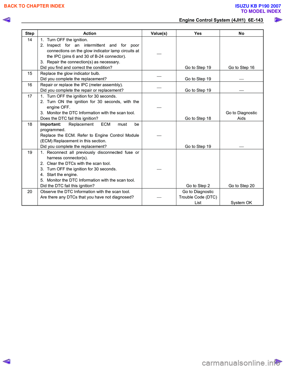
Step Action Value(s) Yes No
14 1. Turn OFF the ignition.
2. Inspect for an intermittent and for poor connections on the glow indicator lamp circuits at
the IPC (pins 6 and 30 of B-24 connector).
3. Repair the connection(s) as necessary.
Did you find and correct the condition?
Go to Step 19 Go to Step 16
15 Replace the glow indicator bulb. Did you complete the replacement?
Go to Step 19
16 Repair or replace the IPC (meter assembly).
Did you complete the repair or replacement?
Go to Step 19
17 1. Turn OFF the ignition for 30 seconds.
2. Turn ON the ignition for 30 seconds, with the engine OFF.
3. Monitor the DTC Information with the scan tool.
Does the DTC fail this ignition?
Go to Step 18 Go to Diagnostic
Aids
18 Important: Replacement ECM must be
programmed.
Replace the ECM. Refer to Engine Control Module
(ECM) Replacement in this section.
Did you complete the replacement?
Go to Step 19
19 1. Reconnect all previously disconnected fuse or
harness connector(s).
2. Clear the DTCs with the scan tool.
3. Turn OFF the ignition for 30 seconds.
4. Start the engine.
5. Monitor the DTC Information with the scan tool.
Did the DTC fail this ignition?
Go to Step 2 Go to Step 20
20 Observe the DTC Information with the scan tool. Are there any DTCs that you have not diagnosed? Go to Diagnostic
Trouble Code (DTC) List System OK
BACK TO CHAPTER INDEX
TO MODEL INDEX
ISUZU KB P190 2007
Page 1268 of 6020

6E-234 Engine Control System (4JH1)
DTC P1690 (Symptom Code 4) (Flash Code 77)
Circuit Description
The malfunction indicator lamp (MIL) is located on the
instrument panel cluster (IPC). The battery voltage is
supplied to the MIL. The engine control module (ECM)
turns the MIL ON by grounding the MIL control circuit.
After a fixed time passes, the ECM turns OFF the MIL
with the ignition ON and the engine OFF. The MIL has
the following functions:
• The MIL informs the driver that a malfunction has
occurred and the vehicle should be taken in fo
r
service as soon as possible.
• The MIL illuminates during a bulb test and a
system test.
•
A DTC will be stored if a MIL is requested by the
ECM.
If the ECM detects an open circuit or short circuit on the
MIL control circuit, this DTC will set.
Condition for Running the DTC • The ignition switch is ON.
Condition for Setting the DTC
• The ECM detects a low voltage condition on the
MIL control circuit for longer than 3 seconds when
the MIL is commanded OFF.
Action Taken When the DTC Sets • The ECM does not illuminates the MIL when the
diagnostic runs and fails.
Condition for Clearing the DTC • A history DTC clears after 40 consecutive driving
cycles without a fault. Or clear with the scan tool.
Diagnostic Aids
• If an intermittent condition is suspected, refer to
Intermittent Conditions in this section.
DTC P1690 (Symptom Code 4) (Flash Code 77)
Schematic Reference: Engine Controls Schematics
Connector End View Reference: Engine Controls
Connector End Views or Engine Control Module (ECM)
Connector End Views
Step Action Value(s) Yes No
1 Did you perform the Diagnostic System Check-
Engine Controls?
Go to Step 2 Go to Diagnostic
System Check-
Engine Controls
2 1. Install the scan tool. 2. Turn ON the ignition, with the engine OFF.
3. Perform the Malfunction Indicator Lamp (MIL) test with the scan tool.
4. Command the MIL ON with the scan tool.
Does the MIL turn ON when commanded ON with
the scan tool?
Go to Step 3 Go to Step 4
3 Command the MIL OFF with the scan tool. Does the MIL OFF?
Go to Step 17 Go to Step 10
4 1. Turn OFF the ignition.
2. Inspect the Meter (15A) fuse (C-14) in the cabin fuse block.
Is the Meter (15A) fuse (C-14) open?
Go to Step 5 Go to Step 6
5 Replace the Meter (15A) fuse (C-14). If the fuse continues to open, repair the short to ground on one
of the circuits that fed by the Meter (15A) fuse (C-14)
or replace the shorted attached component fed by
the Meter (15A) fuse (C-14).
Did you complete the repair?
Go to Step 19
6 1. Turn OFF the ignition.
2. Disconnect the engine control module (ECM) harness connector.
3. Turn ON the ignition, with the engine OFF.
4. Connect a 3-amp fused jumper wire between the MIL control circuit of the ECM harness connector
(pin 42 of C-56 connector) and a known good
ground.
Does the MIL illuminate?
Go to Step 11 Go to Step 7
BACK TO CHAPTER INDEX
TO MODEL INDEX
ISUZU KB P190 2007
Page 1269 of 6020
Engine Control System (4JH1) 6E-235
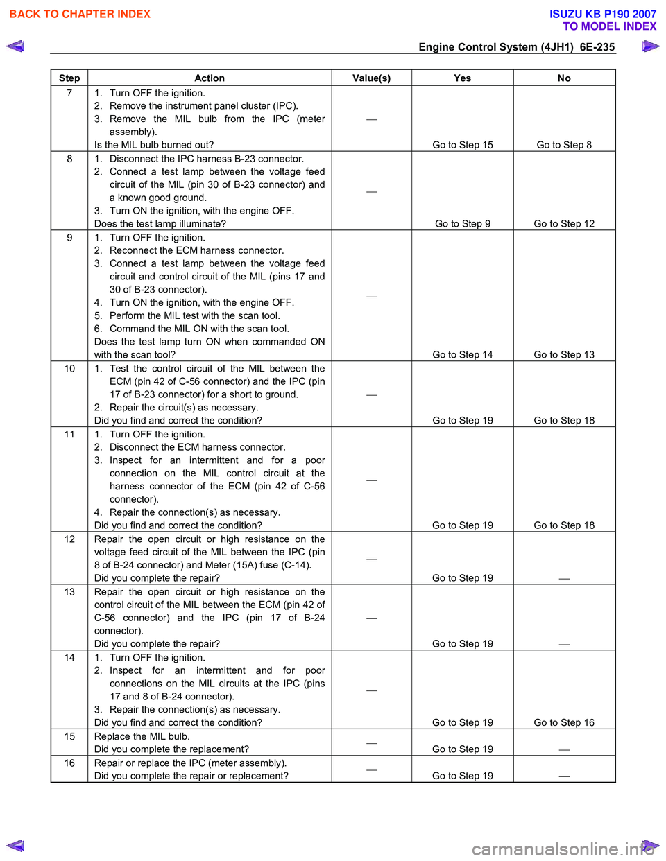
Step Action Value(s) Yes No
7 1. Turn OFF the ignition.
2. Remove the instrument panel cluster (IPC).
3. Remove the MIL bulb from the IPC (meter assembly).
Is the MIL bulb burned out?
Go to Step 15 Go to Step 8
8 1. Disconnect the IPC harness B-23 connector. 2. Connect a test lamp between the voltage feed circuit of the MIL (pin 30 of B-23 connector) and
a known good ground.
3. Turn ON the ignition, with the engine OFF.
Does the test lamp illuminate?
Go to Step 9 Go to Step 12
9 1. Turn OFF the ignition. 2. Reconnect the ECM harness connector.
3. Connect a test lamp between the voltage feed circuit and control circuit of the MIL (pins 17 and
30 of B-23 connector).
4. Turn ON the ignition, with the engine OFF.
5. Perform the MIL test with the scan tool.
6. Command the MIL ON with the scan tool.
Does the test lamp turn ON when commanded ON
with the scan tool?
Go to Step 14 Go to Step 13
10 1. Test the control circuit of the MIL between the ECM (pin 42 of C-56 connector) and the IPC (pin
17 of B-23 connector) for a short to ground.
2. Repair the circuit(s) as necessary.
Did you find and correct the condition?
Go to Step 19 Go to Step 18
11 1. Turn OFF the ignition. 2. Disconnect the ECM harness connector.
3. Inspect for an intermittent and for a poor connection on the MIL control circuit at the
harness connector of the ECM (pin 42 of C-56
connector).
4. Repair the connection(s) as necessary.
Did you find and correct the condition?
Go to Step 19 Go to Step 18
12 Repair the open circuit or high resistance on the voltage feed circuit of the MIL between the IPC (pin
8 of B-24 connector) and Meter (15A) fuse (C-14).
Did you complete the repair?
Go to Step 19
13 Repair the open circuit or high resistance on the
control circuit of the MIL between the ECM (pin 42 of
C-56 connector) and the IPC (pin 17 of B-24
connector).
Did you complete the repair?
Go to Step 19
14 1. Turn OFF the ignition.
2. Inspect for an intermittent and for poor connections on the MIL circuits at the IPC (pins
17 and 8 of B-24 connector).
3. Repair the connection(s) as necessary.
Did you find and correct the condition?
Go to Step 19 Go to Step 16
15 Replace the MIL bulb. Did you complete the replacement?
Go to Step 19
16 Repair or replace the IPC (meter assembly).
Did you complete the repair or replacement?
Go to Step 19
BACK TO CHAPTER INDEX
TO MODEL INDEX
ISUZU KB P190 2007
Page 1271 of 6020
Engine Control System (4JH1) 6E-237
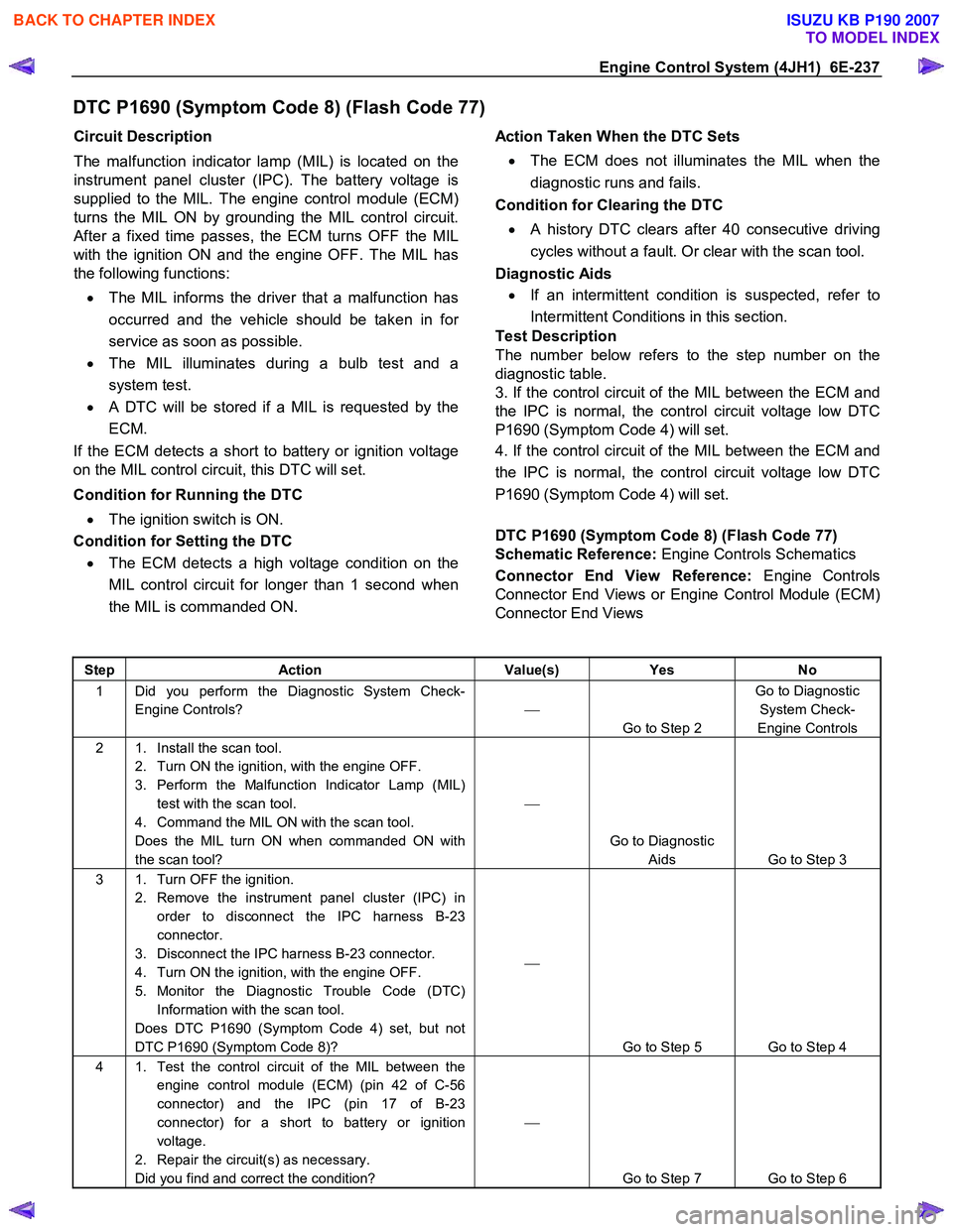
DTC P1690 (Symptom Code 8) (Flash Code 77)
Circuit Description
The malfunction indicator lamp (MIL) is located on the
instrument panel cluster (IPC). The battery voltage is
supplied to the MIL. The engine control module (ECM)
turns the MIL ON by grounding the MIL control circuit.
After a fixed time passes, the ECM turns OFF the MIL
with the ignition ON and the engine OFF. The MIL has
the following functions:
• The MIL informs the driver that a malfunction has
occurred and the vehicle should be taken in fo
r
service as soon as possible.
• The MIL illuminates during a bulb test and a
system test.
•
A DTC will be stored if a MIL is requested by the
ECM.
If the ECM detects a short to battery or ignition voltage
on the MIL control circuit, this DTC will set.
Condition for Running the DTC • The ignition switch is ON.
Condition for Setting the DTC
• The ECM detects a high voltage condition on the
MIL control circuit for longer than 1 second when
the MIL is commanded ON.
Action Taken When the DTC Sets
• The ECM does not illuminates the MIL when the
diagnostic runs and fails.
Condition for Clearing the DTC
• A history DTC clears after 40 consecutive driving
cycles without a fault. Or clear with the scan tool.
Diagnostic Aids
• If an intermittent condition is suspected, refer to
Intermittent Conditions in this section.
Test Description
The number below refers to the step number on the
diagnostic table.
3. If the control circuit of the MIL between the ECM and
the IPC is normal, the control circuit voltage low DTC
P1690 (Symptom Code 4) will set.
4. If the control circuit of the MIL between the ECM and
the IPC is normal, the control circuit voltage low DTC
P1690 (Symptom Code 4) will set.
DTC P1690 (Symptom Code 8) (Flash Code 77)
Schematic Reference: Engine Controls Schematics
Connector End View Reference: Engine Controls
Connector End Views or Engine Control Module (ECM)
Connector End Views
Step Action Value(s) Yes No
1 Did you perform the Diagnostic System Check-
Engine Controls?
Go to Step 2 Go to Diagnostic
System Check-
Engine Controls
2 1. Install the scan tool. 2. Turn ON the ignition, with the engine OFF.
3. Perform the Malfunction Indicator Lamp (MIL) test with the scan tool.
4. Command the MIL ON with the scan tool.
Does the MIL turn ON when commanded ON with
the scan tool?
Go to Diagnostic Aids Go to Step 3
3 1. Turn OFF the ignition. 2. Remove the instrument panel cluster (IPC) in order to disconnect the IPC harness B-23
connector.
3. Disconnect the IPC harness B-23 connector.
4. Turn ON the ignition, with the engine OFF.
5. Monitor the Diagnostic Trouble Code (DTC) Information with the scan tool.
Does DTC P1690 (Symptom Code 4) set, but not
DTC P1690 (Symptom Code 8)?
Go to Step 5 Go to Step 4
4 1. Test the control circuit of the MIL between the engine control module (ECM) (pin 42 of C-56
connector) and the IPC (pin 17 of B-23
connector) for a short to battery or ignition
voltage.
2. Repair the circuit(s) as necessary.
Did you find and correct the condition?
Go to Step 7 Go to Step 6
BACK TO CHAPTER INDEX
TO MODEL INDEX
ISUZU KB P190 2007
Page 1318 of 6020
6E-284 Engine Control System (4JH1)
Important:
To prevent possible electrostatic discharge damage,
follow these guidelines: • Do not touch the ECM connector pins or soldered
components on the ECM circuit board.
• Do not open the replacement part package until
the part is ready to be installed.
• Before removing the part from the package,
ground the package to a known good ground on
the vehicle.
• If the part has been handled while sliding across
the seat, while sitting down from a standing
position, or while walking a distance, touch a
known good ground before installing the part.
• Charge by induction occurs when a person with
well insulated shoes stands near a highly charged
object and momentarily touches ground. Charges
of the same polarity are drained off leaving the
person highly charged with opposite polarity.
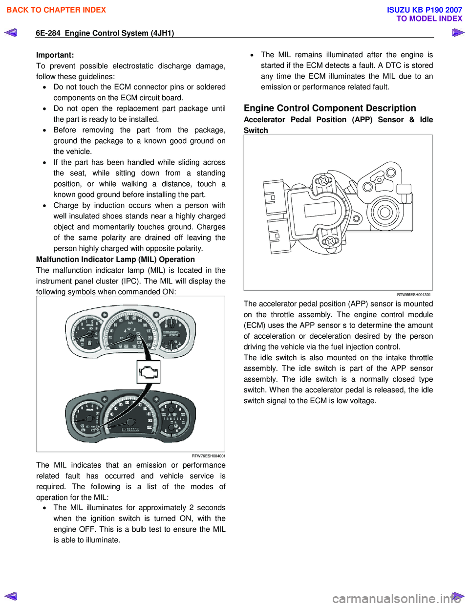
Malfunction Indicator Lamp (MIL) Operation
The malfunction indicator lamp (MIL) is located in the
instrument panel cluster (IPC). The MIL will display the
following symbols when commanded ON:
RTW 76ESH004001
The MIL indicates that an emission or performance
related fault has occurred and vehicle service is
required. The following is a list of the modes o
f
operation for the MIL: • The MIL illuminates for approximately 2 seconds
when the ignition switch is turned ON, with the
engine OFF. This is a bulb test to ensure the MIL
is able to illuminate.
•
The MIL remains illuminated after the engine is
started if the ECM detects a fault. A DTC is stored
any time the ECM illuminates the MIL due to an
emission or performance related fault.
Engine Control Component Description
Accelerator Pedal Position (APP) Sensor & Idle
Switch
RTW 66ESH001301
The accelerator pedal position (APP) sensor is mounted
on the throttle assembly. The engine control module
(ECM) uses the APP sensor s to determine the amount
of acceleration or deceleration desired by the person
driving the vehicle via the fuel injection control.
The idle switch is also mounted on the intake throttle
assembly. The idle switch is part of the APP senso
r
assembly. The idle switch is a normally closed type
switch. W hen the accelerator pedal is released, the idle
switch signal to the ECM is low voltage.
BACK TO CHAPTER INDEX
TO MODEL INDEX
ISUZU KB P190 2007
Page 1595 of 6020
ENGINE ELECTRICAL (4JK1/4JJ1) 6D-7
Diagnosis
On-vehicle Inspection
The charging system warning light tells the vehicle
operator of possible problems with the system.
W hen the ignition switch is moved to the ON position,
the light turns on. The light turns off immediately afte
r
the engine is started. If the light turns on during engine
operation, there is a problem with the charging system.
Perform the checks described below.
1. Check the belt (broken or loose).
2. Check the harness connectors (loose o
r
disconnected).
3. W ith the engine off, turn the ignition switch to the ON position. If the warning lamp does not light,
remove the harness connector from the generator.
Ground the connector IG terminal. The lamp
should light. If it does not, the bulb is burned out.
Replace the bulb.
4. Start the engine. If the warning lamp remains on, the generator must be repaired or replaced.
BACK TO CHAPTER INDEX
TO MODEL INDEX
ISUZU KB P190 2007
Page 1972 of 6020
ENGINE CONTROL SYSTEM (4JK1/4JJ1) 6E-355
Electrostatic Discharge Damage
Electronic components used in the ECM are often
designed to carry very low voltage. Electronic
components are susceptible to damage caused by
electrostatic discharge. By comparison, as much as
4,000 volts may be needed for a person to feel even
the zap of a static discharge. There are several ways
for a person to become statically charged. The most
common methods of charging are by friction and
induction.
• An example of charging by friction is a person sliding across a vehicle seat.
Important: To prevent possible electrostatic discharge
damage, follow these guidelines:
• Do not touch the ECM connector pins or soldered components on the ECM circuit board.
• Do not open the replacement part package until the part is ready to be installed.
• Before removing the part from the package, ground the package to a known good ground on
the vehicle.
• If the part has been handled while sliding across the seat, while sitting down from a standing
position, or while walking a distance, touch a
known good ground before installing the part.
• Charge by induction occurs when a person with well insulated shoes stands near a highly charged
object and momentarily touches ground. Charges
of the same polarity are drained off leaving the
person highly charged with opposite polarity.
Malfunction Indicator Lamp (MIL) Operation
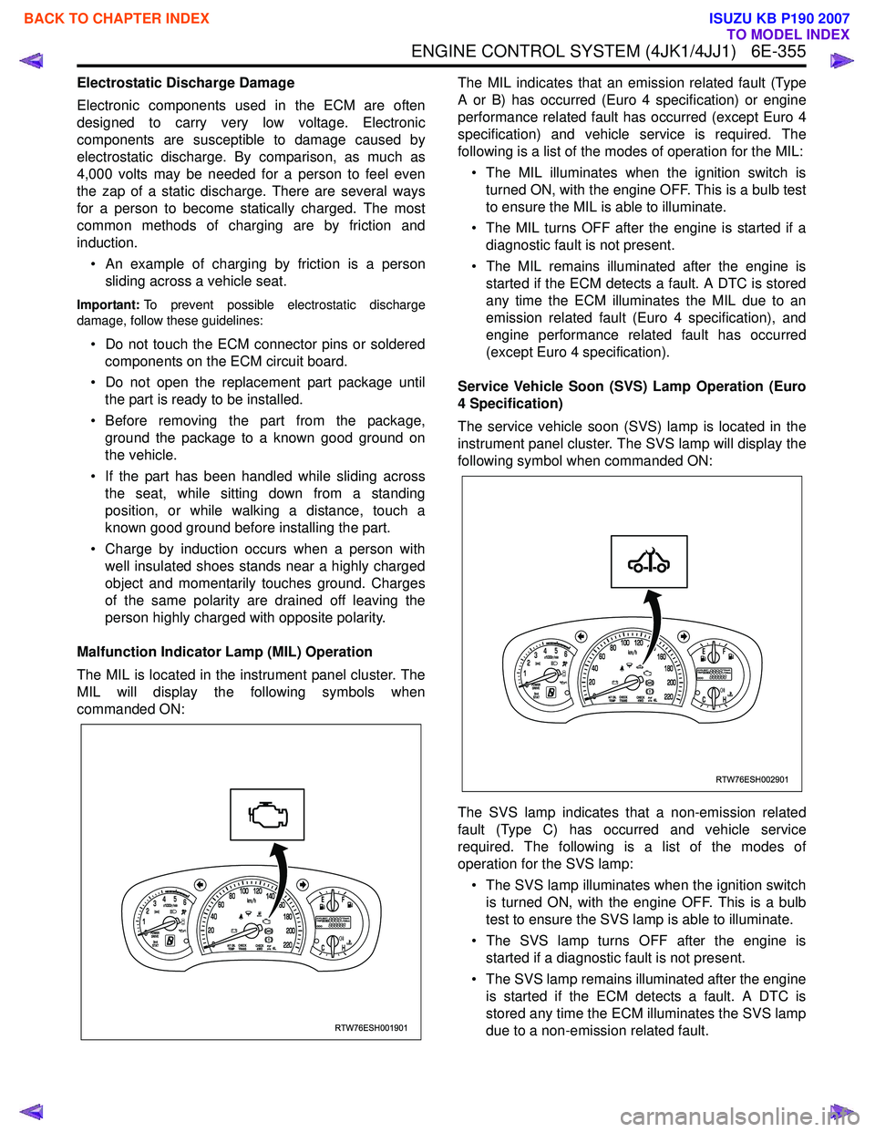
The MIL is located in the instrument panel cluster. The
MIL will display the following symbols when
commanded ON: The MIL indicates that an emission related fault (Type
A or B) has occurred (Euro 4 specification) or engine
performance related fault has occurred (except Euro 4
specification) and vehicle service is required. The
following is a list of the modes of operation for the MIL:
• The MIL illuminates when the ignition switch is turned ON, with the engine OFF. This is a bulb test
to ensure the MIL is able to illuminate.
• The MIL turns OFF after the engine is started if a diagnostic fault is not present.
• The MIL remains illuminated after the engine is started if the ECM detects a fault. A DTC is stored
any time the ECM illuminates the MIL due to an
emission related fault (Euro 4 specification), and
engine performance related fault has occurred
(except Euro 4 specification).
Service Vehicle Soon (SVS) Lamp Operation (Euro
4 Specification)
The service vehicle soon (SVS) lamp is located in the
instrument panel cluster. The SVS lamp will display the
following symbol when commanded ON:
The SVS lamp indicates that a non-emission related
fault (Type C) has occurred and vehicle service
required. The following is a list of the modes of
operation for the SVS lamp:
• The SVS lamp illuminates when the ignition switch is turned ON, with the engine OFF. This is a bulb
test to ensure the SVS lamp is able to illuminate.
• The SVS lamp turns OFF after the engine is started if a diagnostic fault is not present.
• The SVS lamp remains illuminated after the engine is started if the ECM detects a fault. A DTC is
stored any time the ECM illuminates the SVS lamp
due to a non-emission related fault.
RTW76ESH001901
RTW76ESH002901
BACK TO CHAPTER INDEX
TO MODEL INDEX
ISUZU KB P190 2007
Page 2014 of 6020
6-14 ENGINE DIAGNOSIS (C24SE)
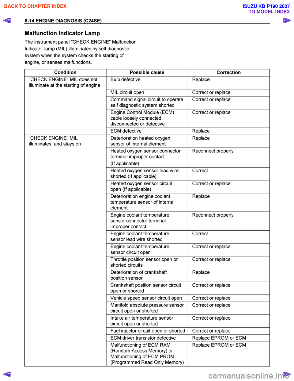
Malfunction Indicator Lamp
The instrument panel "CHECK ENGINE" Malfunction
Indicator lamp (MIL) illuminates by self diagnostic
system when the system checks the starting of
engine, or senses malfunctions.
Condition Possible cause Correction
"CHECK ENGINE" MIL does not
illuminate at the starting of engine Bulb defective Replace
MIL circuit open Correct or replace
Command signal circuit to operate
self diagnostic system shorted Correct or replace
Engine Control Module (ECM)
cable loosely connected,
disconnected or defective Correct or replace
ECM
defective Replace
“CHECK ENGINE” MIL
illuminates, and stays on Deterioration heated oxygen
sensor of internal element Replace
Heated oxygen sensor connector
terminal improper contact
(If applicable) Reconnect properly
Heated oxygen sensor lead wire
shorted (If applicable) Correct
Heated oxygen sensor circuit
open (If applicable) Correct or replace
Deterioration engine coolant
temperature sensor of internal
element Replace
Engine coolant temperature
sensor connector terminal
improper contact Reconnect properly
Engine coolant temperature
sensor lead wire shorted Correct
Engine coolant temperature
sensor circuit open Correct or replace
Throttle position sensor open or
shorted circuits Correct or replace
Deterioration of crankshaft
position sensor Replace
Crankshaft position sensor circuit
open or shorted Correct or replace
Vehicle speed sensor circuit open Correct or replace
Manifold absolute pressure sensor
circuit open or shorted Correct or replace
Intake air temperature sensor
circuit open or shorted Correct or replace
Fuel injector circuit open or shorted Correct or replace
ECM driver transistor defective Replace EPROM or ECM
Malfunctioning of ECM RAM
(Random Access Memory) or
Malfunctioning of ECM PROM
(Programmed Read Only Memory) Replace EPROM or ECM
BACK TO CHAPTER INDEX
TO MODEL INDEX
ISUZU KB P190 2007