Page 4962 of 6020
8A-24 ELECTRICAL-BODY AND CHASSIS
MAIN DATA AND SPECIFICATIONS
BULB SPECIFICATIONS
This illustration based on LHD
RTW 78AMF000801
Light Name Bulb No. Rated Power
V-W Number
of Bulbs Lens
Color Remarks
H4 12-60/55 2 W hite A type, Halogen
HB3 12-65 2 W hite
H7 12-55 2 W hite A type, Halogen
projector type
HB3 12-60 2 W hite High Bean
Headlight
HB4 12-51 2 W hite B type
Low Bean
High mounted stoplight W 5W 12-5 4 RED
Fog light H3 12-55 2 W hite
Front turn signal light PY21W 12-21 2 W hite Bulb Lens color
Amber
Clearance light W 5W 12-5 2 W hite
Door mirror-turn signal light
(out side mirror type) - -
2 W hite LED (Illuminated
color Amber)
Side turn signal light W 5W 12-5 2 W hite with
amber
inner lens
Rear turn signal light
PY21W 12-21 2 W hite Bulb Lens color
Amber
Rear fog light P21W 12-21 1 Red
Tail and stoplight P21/5W 12-21/5 2 Red
BACK TO CHAPTER INDEX
TO MODEL INDEXISUZU KB P190 2007
Page 4963 of 6020

ELECTRICAL-BODY AND CHASSIS 8A-25
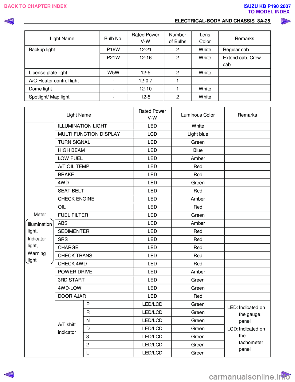
Light Name Bulb No. Rated Power
V-W Number
of Bulbs Lens
Color Remarks
P16W 12-21 2 W hite Regular cab Backup light
P21W 12-16 2 W hite Extend cab, Crew cab
License plate light W 5W 12-5 2 W hite
A/C-Heater control light - 12-0.7 1 -
Dome light - 12-10 1 W hite
Spotlight/ Map light - 12-5 2 W hite
Light Name Rated Power
V-W Luminous Color Remarks
ILLUMINATION
LIGHT LED W hite
MULTI FUNCTION DISPLAY LCD Light blue
TURN SIGNAL LED Green
HIGH BEAM LED Blue
LOW FUEL LED Amber
A/T OIL TEMP LED Red
BRAKE LED Red
4W D LED Green
SEAT BELT LED Red
CHECK ENGINE LED Amber
OIL LED Red
FUEL FILTER LED Green
ABS LED Amber
SEDIMENTER LED Red
SRS LED Red
CHARGE LED Red
CHECK TRANS LED Red
CHECK 4W D LED Red
POW ER DRIVE LED Amber
3RD START LED Green
4W D-LOW LED Green
DOOR AJAR LED Red
P LED/LCD Green
R LED/LCD Green
N LED/LCD Green
D LED/LCD Green
3 LED/LCD Green
2 LED/LCD Green
A/T shift
indicator
L LED/LCD Green LED: Indicated on
the gauge
panel
LCD: Indicated on the
tachometer
panel
Meter
Illumination
light,
Indicator
light,
W arning
light
BACK TO CHAPTER INDEX TO MODEL INDEXISUZU KB P190 2007
Page 5099 of 6020

ELECTRICAL-BODY AND CHASSIS 8A-161
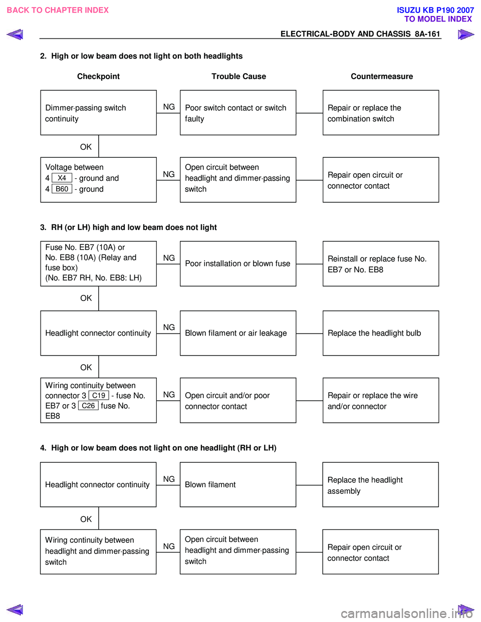
2. High or low beam does not light on both headlights
Checkpoint Trouble Cause Countermeasure
Repair or replace the
combination switch
Dimmer ⋅passing switch
continuity
Poor switch contact or switch
faulty
NG
Repair open circuit or
connector contact
Voltage between
4
X4 - ground and
4
B60 - ground
Open circuit between
headlight and dimmer ⋅passing
switch
NG
OK
3. RH (or LH) high and low beam does not light
Replace the headlight bulb
Headlight connector continuity
Blown filament or air leakage
NG
Repair or replace the wire
and/or connector
W iring continuity between
connector 3
C19 - fuse No.
EB7 or 3
C26 fuse No.
EB8
Open circuit and/or poor
connector contact
NG
OK
Reinstall or replace fuse No.
EB7 or No. EB8
Fuse No. EB7 (10A) or
No. EB8 (10A) (Relay and
fuse box)
(No. EB7 RH, No. EB8: LH)
Poor installation or blown fuse
NG
OK
4. High or low beam does not light on one headlight (RH or LH)
Replace the headlight
assemblyHeadlight connector continuityBlown filament
NG
Repair open circuit or
connector contactW iring continuity between
headlight and dimmer ⋅passing
switchOpen circuit between
headlight and dimmer ⋅passing
switch
NG
OK
BACK TO CHAPTER INDEX
TO MODEL INDEXISUZU KB P190 2007
Page 5100 of 6020

8A-162 ELECTRICAL-BODY AND CHASSIS
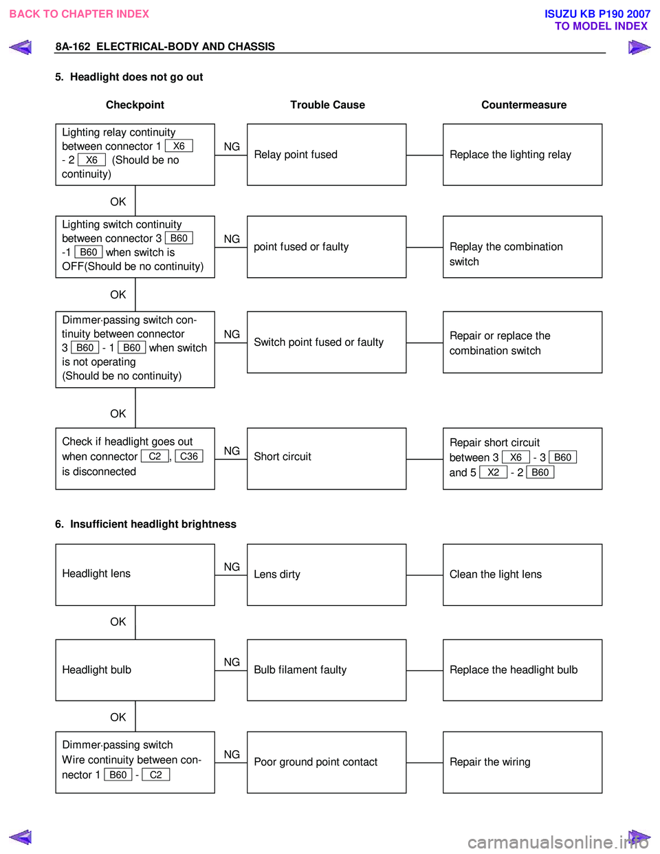
5. Headlight does not go out
Checkpoint Trouble Cause Countermeasure
Replace the lighting relay
Lighting relay continuity
between connector 1
X6
- 2
X6 (Should be no
continuity)
Relay point fused
NG
Replay the combination
switch Lighting switch continuity
between connector 3
B60
-1
B60 when switch is
OFF(S hould be no continuity)
point fused or faulty
NG
OK
OK
Repair or replace the
combination switch
Dimmer ⋅passing switch con-
tinuity between connector
3
B60 - 1 B60 when switch
is not operating
(Should be no continuity)
Switch point fused or faulty
NG
Repair short circuit
between 3
X6 - 3 B60
and 5
X2 - 2 B60
Check if headlight goes out
when connector
C2 , C36
is disconnected
Short circuit
NG
OK
6. Insufficient headlight brightness
Replace the headlight bulb
Headlight bulb
Bulb filament faulty
NG
Repair the wiring
Dimmer ⋅passing switch
W ire continuity between con-
nector 1
B60 - C2
Poor ground point contact
NG
OK
Clean the light lens
Headlight lens
Lens dirty
NG
OK
BACK TO CHAPTER INDEX
TO MODEL INDEXISUZU KB P190 2007
Page 5102 of 6020
8A-164 ELECTRICAL-BODY AND CHASSIS
TAIL LIGHT, LICENSE PLATE LIGHT, CLEARANCE LIGHT
1. All lights do not light
Checkpoint Trouble Cause Countermeasure
Repair or replace the
combination switch
Lighting switch continuity
between connector
2
B60 - 1 B60
Poor switch point or connector
contact
NG
Reinstall or replace the tail
relay
Tail relay
Poor relay contact or relay
faulty
NG
OK
Reinstall or replace the fuse
No. EB12 (LH), EB11 (RH)
Fuse No. EB12 (LH) or EB11
(RH) (10A, Relay and fuse
box)
Poor fuse contact or blown
NG
OK
2. Tail light does not light
Replace the bulb or repair
connector contact
Tail light bulb continuity
Bulb burned out or poor
connector contact
NG
Repair open circuit or
connector contact
Continuity between connector
3
F5 - 4 F5 (RH)
or 3
F6 - 4 F6 (LH)
Open circuit or poor connector
contact
NG
OK
BACK TO CHAPTER INDEX
TO MODEL INDEXISUZU KB P190 2007
Page 5103 of 6020
ELECTRICAL-BODY AND CHASSIS 8A-165
3. License plate light does not light
Checkpoint Trouble Cause Countermeasure
Repair open circuit or
connector contact
Continuity between
connector 1
T4 - 2 T4 or 1
T3 - 2 T3
Open circuit or poor connector
contact
NG
Replace the bulb or repair
connector contact
License plate light bulb
continuity
Bulb burned out or poor
connector contact
NG
OK
4. Clearance light does not light
Replace the bulb or repair
connector contactClearance light bulb continuityBulb burned out or poor
connector contact
NG
BACK TO CHAPTER INDEX TO MODEL INDEXISUZU KB P190 2007
Page 5104 of 6020

8A-166 ELECTRICAL-BODY AND CHASSIS
LIGHTING SYSTEM
REMOVAL AND INSTALLATION
3 2
1
RTW 78ASH000101
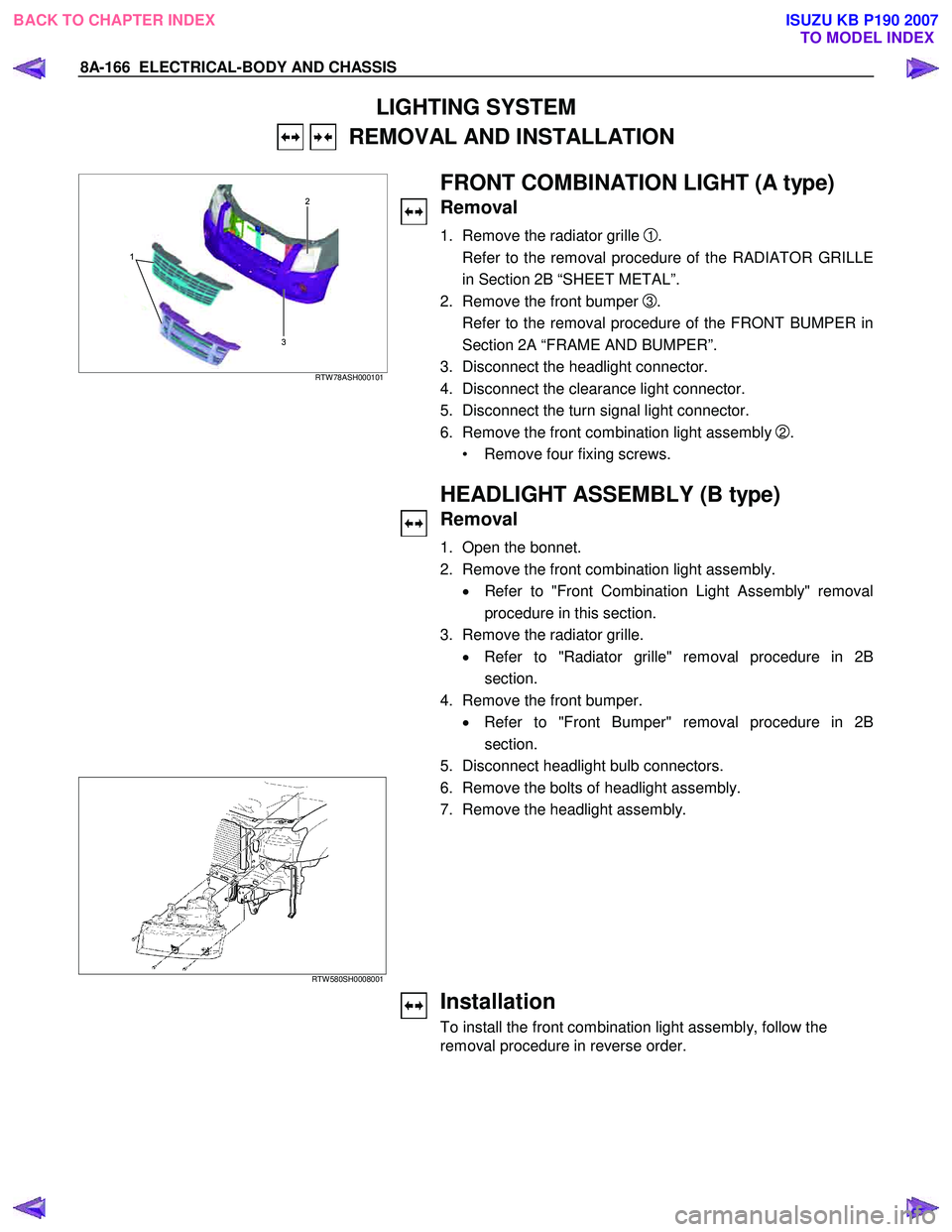
FRONT COMBINATION LIGHT (A type)
Removal
1. Remove the radiator grille 1.
Refer to the removal procedure of the RADIATOR GRILLE
in Section 2B “SHEET METAL”.
2. Remove the front bumper
3.
Refer to the removal procedure of the FRONT BUMPER in
Section 2A “FRAME AND BUMPER”.
3. Disconnect the headlight connector.
4. Disconnect the clearance light connector.
5. Disconnect the turn signal light connector.
6. Remove the front combination light assembly
2.
• Remove four fixing screws.
HEADLIGHT ASSEMBLY (B type)
Removal
1. Open the bonnet.
2. Remove the front combination light assembly. • Refer to "Front Combination Light Assembly" removal
procedure in this section.
3. Remove the radiator grille. • Refer to "Radiator grille" removal procedure in 2B
section.
4. Remove the front bumper. • Refer to "Front Bumper" removal procedure in 2B
section.
5. Disconnect headlight bulb connectors.
RTW 580SH0008001
6. Remove the bolts of headlight assembly. 7. Remove the headlight assembly.
Installation
To install the front combination light assembly, follow the
removal procedure in reverse order.
BACK TO CHAPTER INDEX TO MODEL INDEXISUZU KB P190 2007
Page 5105 of 6020
ELECTRICAL-BODY AND CHASSIS 8A-167
HEADLIGHT (HALOGEN STD TYPE)
(A type)
Removal
1. Remove the head light socket.
2. Remove the headlight dust cover.
3. Slide out the lock spring.
4. Remove the bulb.
1
RTW 78ASH000801
HEADLIGHT (HALOGEN PROJECTOR
TYPE)
Removal
1. Remove the head light socket.
2. Remove the headlight dust cover
1.
1
RTW 78ASH000901
3. Turn the bulb socket counterclockwise to remove it.
4. Remove the headlight bulb
1.
BACK TO CHAPTER INDEX TO MODEL INDEXISUZU KB P190 2007