2007 ISUZU KB P190 bulb
[x] Cancel search: bulbPage 2264 of 6020
6E–94 ENGINE DRIVEABILITY AND EMISSIONS
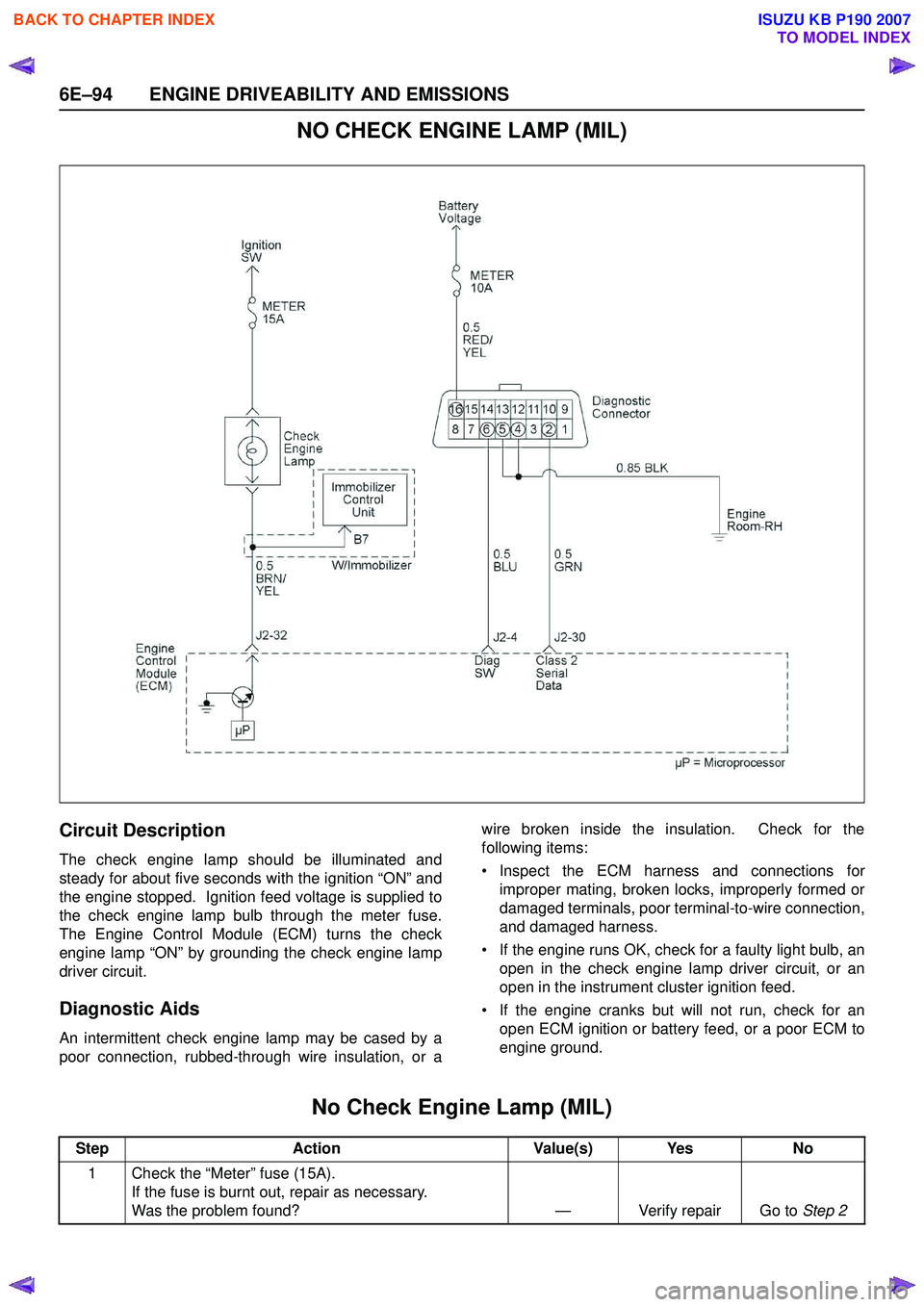
NO CHECK ENGINE LAMP (MIL)
Circuit Description
The check engine lamp should be illuminated and
steady for about five seconds with the ignition “ON” and
the engine stopped. Ignition feed voltage is supplied to
the check engine lamp bulb through the meter fuse.
The Engine Control Module (ECM) turns the check
engine lamp “ON” by grounding the check engine lamp
driver circuit.
Diagnostic Aids
An intermittent check engine lamp may be cased by a
poor connection, rubbed-through wire insulation, or a wire broken inside the insulation. Check for the
following items:
• Inspect the ECM harness and connections for improper mating, broken locks, improperly formed or
damaged terminals, poor terminal-to-wire connection,
and damaged harness.
• If the engine runs OK, check for a faulty light bulb, an open in the check engine lamp driver circuit, or an
open in the instrument cluster ignition feed.
• If the engine cranks but will not run, check for an open ECM ignition or battery feed, or a poor ECM to
engine ground.
No Check Engine Lamp (MIL)
Step Action Value(s) Yes No
1 Check the “Meter” fuse (15A). If the fuse is burnt out, repair as necessary.
Was the problem found? — Verify repair Go to Step 2
BACK TO CHAPTER INDEX
TO MODEL INDEX
ISUZU KB P190 2007
Page 2265 of 6020
ENGINE DRIVEABILITY AND EMISSIONS 6E–95
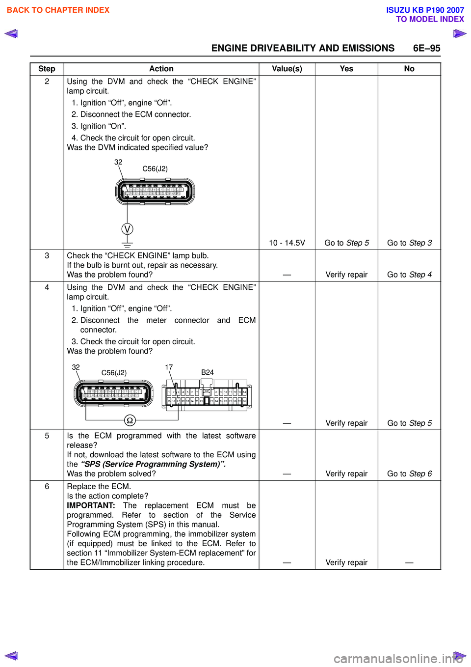
2 Using the DVM and check the “CHECK ENGINE”lamp circuit.
1. Ignition “Off”, engine “Off”.
2. Disconnect the ECM connector.
3. Ignition “On”.
4. Check the circuit for open circuit.
Was the DVM indicated specified value?
10 - 14.5V Go to Step 5Go to Step 3
3 Check the “CHECK ENGINE” lamp bulb. If the bulb is burnt out, repair as necessary.
Was the problem found? — Verify repair Go to Step 4
4 Using the DVM and check the “CHECK ENGINE” lamp circuit.
1. Ignition “Off”, engine “Off”.
2. Disconnect the meter connector and ECM connector.
3. Check the circuit for open circuit.
Was the problem found?
— Verify repair Go to Step 5
5 Is the ECM programmed with the latest software release?
If not, download the latest software to the ECM using
the “SPS (Service Programming System)”.
Was the problem solved? — Verify repair Go to Step 6
6 Replace the ECM. Is the action complete?
IMPORTANT: The replacement ECM must be
programmed. Refer to section of the Service
Programming System (SPS) in this manual.
Following ECM programming, the immobilizer system
(if equipped) must be linked to the ECM. Refer to
section 11 “Immobilizer System-ECM replacement” for
the ECM/Immobilizer linking procedure. — Verify repair —
Step
Action Value(s) Yes No
V
32C56(J2)
3217C56(J2)B24
BACK TO CHAPTER INDEX
TO MODEL INDEX
ISUZU KB P190 2007
Page 2379 of 6020
ENGINE DRIVEABILITY AND EMISSIONS 6E–209
Diagnostic Trouble Code (DTC) P0650
Malfunction Indicator Lamp (MIL) Control Circuit Malfunction
Step Action Value(s) Yes No
1 Was the “On-Board Diagnostic (OBD) System Check” performed?
—Go to Step 2Go to
On Board
Diagnostic
(OBD) System Check
2 1. Connect the Tech 2. 2. Review and record the failure information.
3. Select “F0: Read DTC Infor By Priority” in “F0: Diagnostic Trouble Code”.
Is the DTC P0650 stored as “Present Failure”? — Go to Step 3Refer to
Diagnostic Aids and Go to Step
3
3 1. Using the Tech2, ignition “On” and engine “Off”. 2. Select “Clear DTC Information” with the Tech2 andclear the DTC information.
3. Operate the vehicle and monitor the “F5: Failed This Ignition” in “F2: DTC Information”.
Was the DTC P0650 stored in this ignition cycle? — Go to Step 4Refer to
Diagnostic Aids and Go to Step
4
4 1. Ignition “On”, engine “Off”. 2. Check the “Check Engine” lamp.
Does the lamp turn “On”? — Go to Step 5Go to Step 6
5 1. Ignition “On”, engine “Off”. 2. Check the “Check Engine” lamp.
Does the lamp turn “Off”? — Go to Step 9Go to Step 7
6 Check the “Check Engine” lamp bulb. If the bulb is burnt out, repair as necessary.
Was the problem found? — Verify repair Go to Step 7
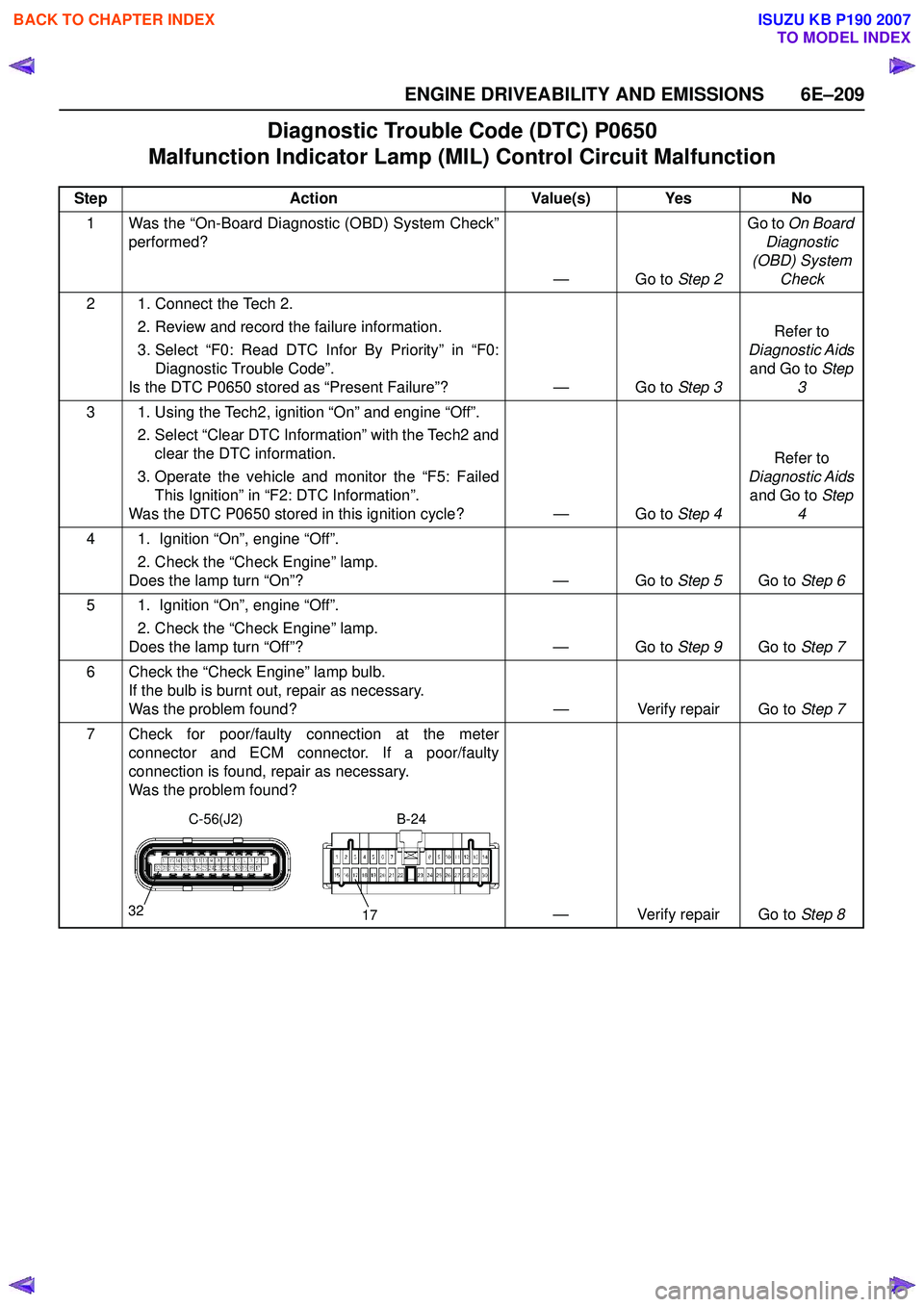
7 Check for poor/faulty connection at the meter connector and ECM connector. If a poor/faulty
connection is found, repair as necessary.
Was the problem found?
— Verify repair Go to Step 8
32
17
C-56(J2)B-24
BACK TO CHAPTER INDEX
TO MODEL INDEX
ISUZU KB P190 2007
Page 3154 of 6020
Engine Cooling – V6 Engine Page 6B1–19
a Place a few drops of distilled water (between 21 and 29° C) onto the measuring window, then close the
plastic cover.
b Point the tester toward any light source, look into the eyepiece and check that the indicated reading is zero. If not, then re-calibrate the tester as detailed at the end of this Test Method, Calibrating the Tester.
2 Release the tip of the bulb pump from under the refractometer body. It is not necessary to remove the
complete pump from the tool.
Refer to 3.1 Service Notes in this
Section, for important safety items.
3 Carefully remove the coolant filler cap.
4 Insert the tube of the pump into the coolant, and then press the bulb to obtain a sample.
5 Bend the tube around and insert the end into the cover plate opening.
Figure 6B1 – 15
6 Press the pump bulb to deposit a few drops of coolant onto the measuring surface. Do not open the plastic cover when taking readings, as moisture evaporation will change the reading obtained.
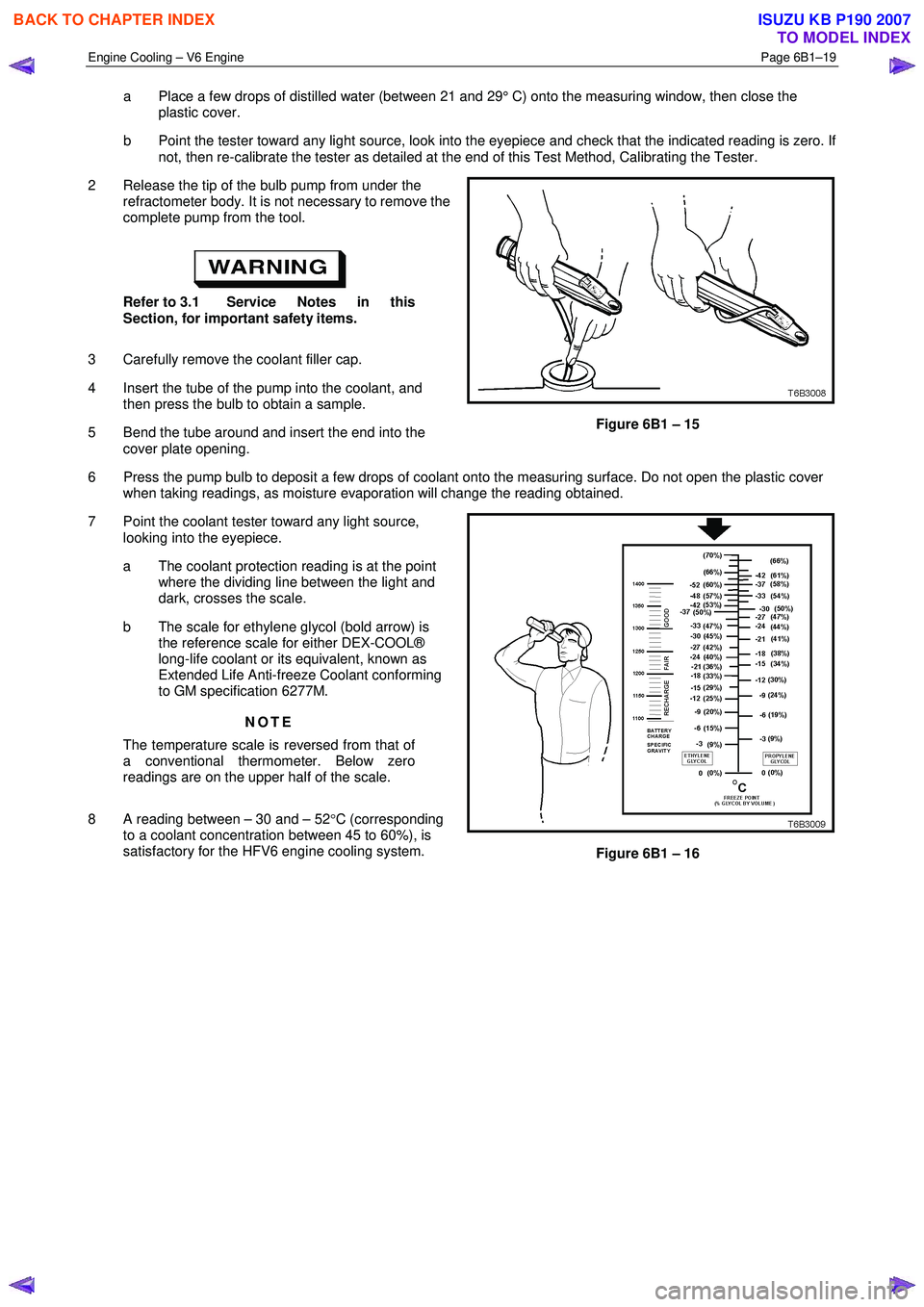
7 Point the coolant tester toward any light source, looking into the eyepiece.
a The coolant protection reading is at the point where the dividing line between the light and
dark, crosses the scale.
b The scale for ethylene glycol (bold arrow) is the reference scale for either DEX-COOL®
long-life coolant or its equivalent, known as
Extended Life Anti-freeze Coolant conforming
to GM specification 6277M.
NOTE
The temperature scale is reversed from that of
a conventional thermometer. Below zero
readings are on the upper half of the scale.
8 A reading between – 30 and – 52 °C (corresponding
to a coolant concentration between 45 to 60%), is
satisfactory for the HFV6 engine cooling system.
Figure 6B1 – 16
BACK TO CHAPTER INDEX
TO MODEL INDEX
ISUZU KB P190 2007
Page 3156 of 6020
Engine Cooling – V6 Engine Page 6B1–21
Calibrating the Tester
The coolant tester calibration is checked at manufacture. If however, the calibration check detailed in Step 1 of this
method shows that the instrument is not reading correctly, then conduct the following recalibration procedure:
1 Remove the sealant covering the adjustment screw on the underneath of the tester.
2 W ith a distilled water sample on the measuring surface, carefully adjust the screw until a zero reading is obtained.
NOTE
DO NOT completely remove the screw.
3 After recalibration, reseal the screw with a small amount of silicone sealant.
Method 2 – Hydrometer
1 The cooling system should be at or close to ambient temperature.
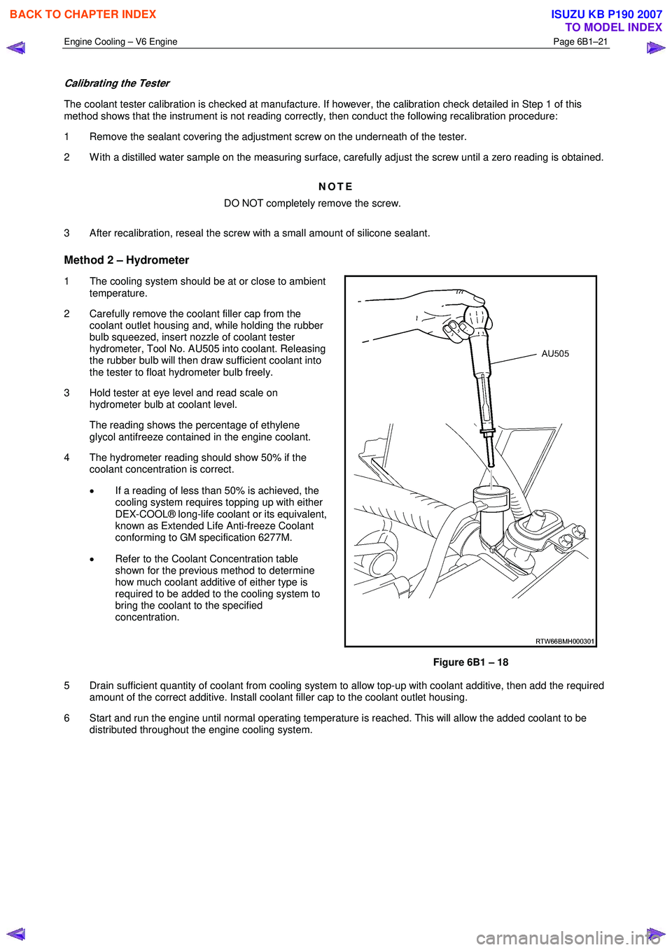
2 Carefully remove the coolant filler cap from the coolant outlet housing and, while holding the rubber
bulb squeezed, insert nozzle of coolant tester
hydrometer, Tool No. AU505 into coolant. Releasing
the rubber bulb will then draw sufficient coolant into
the tester to float hydrometer bulb freely.
3 Hold tester at eye level and read scale on hydrometer bulb at coolant level.
The reading shows the percentage of ethylene glycol antifreeze contained in the engine coolant.
4 The hydrometer reading should show 50% if the coolant concentration is correct.
• If a reading of less than 50% is achieved, the
cooling system requires topping up with either
DEX-COOL® long-life coolant or its equivalent,
known as Extended Life Anti-freeze Coolant
conforming to GM specification 6277M.
• Refer to the Coolant Concentration table
shown for the previous method to determine
how much coolant additive of either type is
required to be added to the cooling system to
bring the coolant to the specified
concentration.
Figure 6B1 – 18
5 Drain sufficient quantity of coolant from cooling system to allow top-up with coolant additive, then add the required amount of the correct additive. Install coolant filler cap to the coolant outlet housing.
6 Start and run the engine until normal operating temperature is reached. This will allow the added coolant to be distributed throughout the engine cooling system.
BACK TO CHAPTER INDEX
TO MODEL INDEX
ISUZU KB P190 2007
Page 3649 of 6020
Battery Page 6D1-3–9
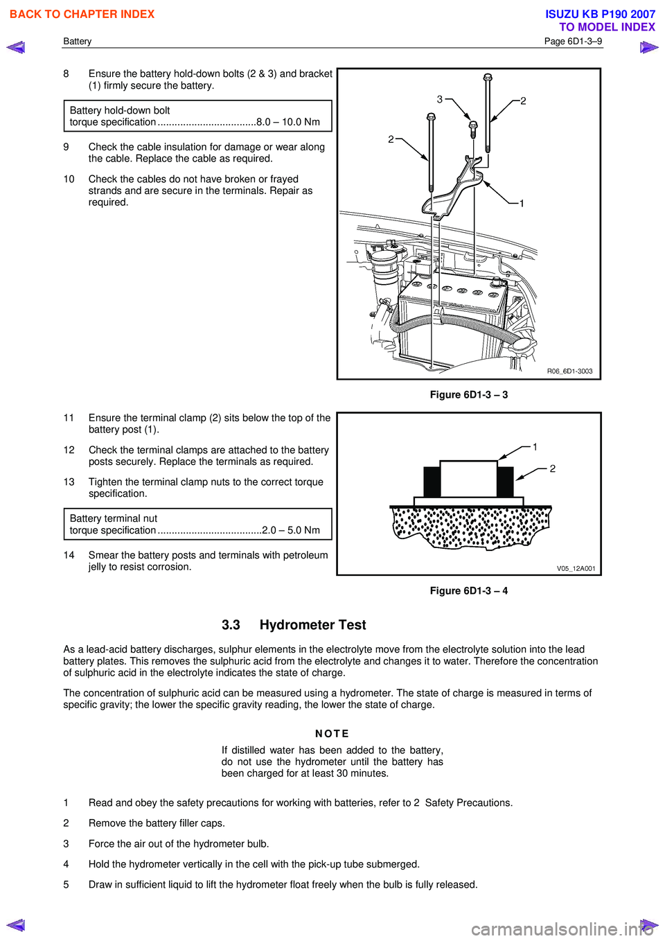
8 Ensure the battery hold-down bolts (2 & 3) and bracket
(1) firmly secure the battery.
Battery hold-down bolt
torque specification ...................................8.0 – 10.0 Nm
9 Check the cable insulation for damage or wear along the cable. Replace the cable as required.
10 Check the cables do not have broken or frayed strands and are secure in the terminals. Repair as
required.
Figure 6D1-3 – 3
11 Ensure the terminal clamp (2) sits below the top of the battery post (1).
12 Check the terminal clamps are attached to the battery posts securely. Replace the terminals as required.
13 Tighten the terminal clamp nuts to the correct torque specification.
Battery terminal nut
torque specification .....................................2.0 – 5.0 Nm
14 Smear the battery posts and terminals with petroleum jelly to resist corrosion.
Figure 6D1-3 – 4
3.3 Hydrometer Test
As a lead-acid battery discharges, sulphur elements in the electrolyte move from the electrolyte solution into the lead
battery plates. This removes the sulphuric acid from the electrolyte and changes it to water. Therefore the concentration
of sulphuric acid in the electrolyte indicates the state of charge.
The concentration of sulphuric acid can be measured using a hydrometer. The state of charge is measured in terms of
specific gravity; the lower the specific gravity reading, the lower the state of charge.
NOTE
If distilled water has been added to the battery,
do not use the hydrometer until the battery has
been charged for at least 30 minutes.
1 Read and obey the safety precautions for working with batteries, refer to 2 Safety Precautions.
2 Remove the battery filler caps.
3 Force the air out of the hydrometer bulb.
4 Hold the hydrometer vertically in the cell with the pick-up tube submerged.
5 Draw in sufficient liquid to lift the hydrometer float freely when the bulb is fully released.
BACK TO CHAPTER INDEX
TO MODEL INDEX
ISUZU KB P190 2007
Page 4438 of 6020
7A2-154 TRANSMISSION CONTROL SYSTEM (JR405E)
Check Trans Lamp Operation
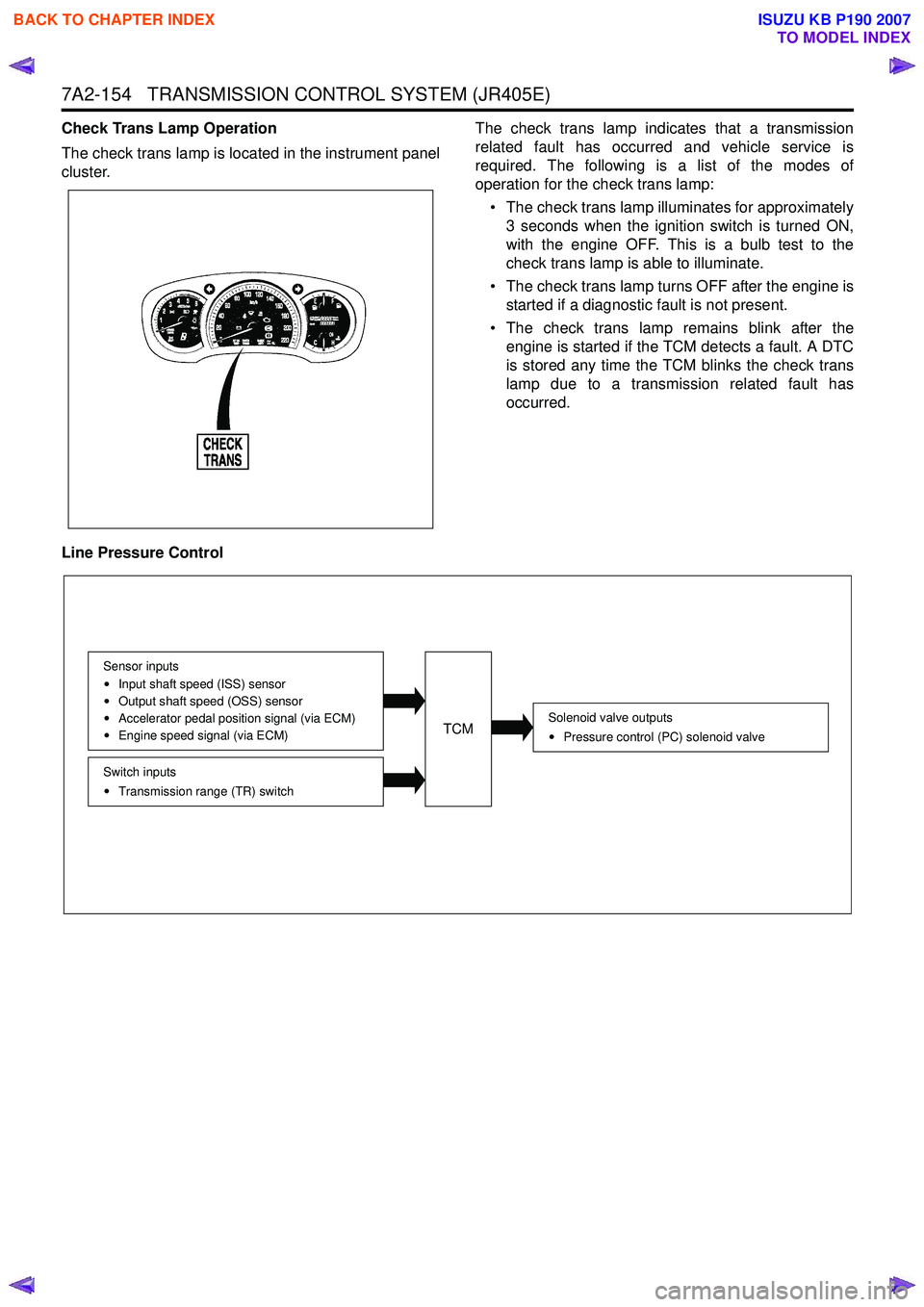
The check trans lamp is located in the instrument panel
cluster. The check trans lamp indicates that a transmission
related fault has occurred and vehicle service is
required. The following is a list of the modes of
operation for the check trans lamp:
• The check trans lamp illuminates for approximately 3 seconds when the ignition switch is turned ON,
with the engine OFF. This is a bulb test to the
check trans lamp is able to illuminate.
• The check trans lamp turns OFF after the engine is started if a diagnostic fault is not present.
• The check trans lamp remains blink after the engine is started if the TCM detects a fault. A DTC
is stored any time the TCM blinks the check trans
lamp due to a transmission related fault has
occurred.
Line Pressure Control
Solenoid valve outputs Pressure control (PC) solenoid valve
Switch inputsTransmission range (TR) switch
Sensor inputs
Input shaft speed (ISS) sensor
Output shaft speed (OSS) sensor
Accelerator pedal position signal (via ECM)
Engine speed signal (via ECM)TCM
BACK TO CHAPTER INDEX
TO MODEL INDEX
ISUZU KB P190 2007
Page 4939 of 6020
ELECTRICAL-BODY AND CHASSIS 8A-1
SECTION 8A
ELECTRICAL-BODY AND CHASSIS
TABLE OF CONTENTS
PAGE
General Information ........................................................................................................... .........8A- 4
Notes for Working on Electrical Items .......................................................................................8A - 5
Symbols and A bbreviations ..................................................................................................... ..8A- 11
Symbols ....................................................................................................................... ................ 8A- 11
Abbreviations ................................................................................................................. ..............8A- 12
Parts for Electri cal Circuit .................................................................................................. ........8A- 13
Wiring ........................................................................................................................ ...................8A- 13
Fuse .......................................................................................................................... ....................8A- 15
Fusible Link .................................................................................................................. ...............8A- 15
Relay ......................................................................................................................... ....................8A- 16
Diode ......................................................................................................................... ...................8A- 17
Connector ..................................................................................................................... ...............8A- 18
Battery ....................................................................................................................... ...................8A- 19
Reading the Circuit Diagram ................................................................................................... ...8A- 22
Parts Location ................................................................................................................ ..............8A- 22
Circuit Diagram ............................................................................................................... .............8A- 23
Connector List ................................................................................................................ .............8A- 23
Main Data and Specifications .................................................................................................. ...8A- 24
Bulb Specifications ........................................................................................................... ..........8A- 24
Relay and Fuse ................................................................................................................ ............8A- 26
Relay and Fuse Box Location (RHD) .........................................................................................8A- 26
Relay and Fuse Box Location (LHD) ..........................................................................................8A- 27
Relay Location ................................................................................................................ .............8A- 28
Fuse and Slow Blow Fuse Location ...........................................................................................8A- 31
Fuse Location ................................................................................................................. .............8A- 33
Diode Location ................................................................................................................ .............8A- 34
Fuse Block Circuit (C24SE) .................................................................................................... ....8A- 35/36
Fuse Block Circuit (HFV6) ...................................................................................................... .....8A- 37
BACK TO CHAPTER INDEX
TO MODEL INDEX
ISUZU KB P190 2007