2007 ISUZU KB P190 ECU
[x] Cancel search: ECUPage 4083 of 6020
TRANSMISSION CONTROL SYSTEM (AW30–40LE) 7A2-117
(3) All of the following conditions are met.
• Device Control is not operating.
• Disable Normal Communication is receiving
enable.
• DTC Clear is not operating.
(4) DTC U2104 is not detecting failure or not deciding failure.
Condition For Setting The DTC
Detection standard is met for 2.5 second continuously.
Detection standard:
If one or more ID sent from Engine Control Module
(ECM) is not completed receiving for 2 basic cycles
since last receiving completion.
Action Taken When The DTC Sets
• Throttle judgment on torque reduction control, line
pressure control at stationary status, line pressure
reduction control at gear change and line pressure
reduction control at garage. (Throttle opening 100%)
• Line pressure FULL output.
• Throttle judgment on gear change control (Throttle
opening 0%).
• No line pressure reduction control at gear change.
• No torque reduction control.
• No squat control.
• No slope control (keep mode).
• No L-up control.
• Control Engine rpm at 7000rpm (No inertia
calculation).
• Control actual torque at MAX.
• Control driver torque at MAX.
• Control engine coolant temperature at 80 °C (176 °F).
• No coast control.
• No 3rd Start mode control.
• No line pressure reduction control at garage.
• No output revolution sensor failure detection.
• No C-0 rev sensor failure detection.
• No selector position switch failure detection.
• No oil temperature sensor failure detection.
• No T/F Hi-Low SW failure detection (Execute T/F
judgment using only T/F-SW ).
• No speed mater signal failure detection.
• No throttle signal failure detection.
• No Engine torque signal failure detection.
• No engine coolant temperature signal failure
detection.
• No Engine revolution signal failure detection.
• No shift solenoid functional failure detection.
• No L-up solenoid functional failure detection.
• Cancel engine rpm condition of prerequisite of suppl
y
voltage failure detection.
• Control vehicle speed of speed meter at 0km/h.
• No torque reduction at stall.
• No cruise control.
• No warm up control.
• Check Trans “ON”.
• DTC stored.
• MIL request “ON”. (EURO 4 only)
Conditions For Clearing The DTC
• The DTC can be cleared from the TCM history by
using a scan tool.
• The DTC will be cleared from history when the vehicle has achieved 40 warm-up cycles without a
failure reported.
• After more than 1 second has elapsed after the ignition key has been turned “ON”, short between
No.11 and No.4 (ground) of DLC (Data Link
Connector). Then, after 1 second, but within 6
seconds, discontinue shorting.
Diagnostic Aids
• Inspect the wiring for poor electrical connection at the
TCM. Look for possible bent, backed out, deformed
or damaged terminals. Check for weak terminal
tension as well. Also check for a chafed wire that
could short to bare metal or other wiring. Inspect for a
broken wire inside the insulation.
• W hen diagnosing for a possible intermittent short o
r
open condition, move the wiring harness while
observing test equipment for a change.
• Inspect the wiring for EMI (Electro-Magnetic
Interference). Check that all wires are properly routed
away from coil, and generator. Also check fo
r
improperly installed electrical options. W hen this test
is performed, turn “OFF” on electronic auto parts
switches to improperly for a noise preventing.
BACK TO CHAPTER INDEX
TO MODEL INDEX
ISUZU KB P190 2007
Page 4104 of 6020
ON-VEHICLE SERVICE (AW30–40LE) 7A3-19
ATF Replacement
Inspection
NOTE: Do not overfill.
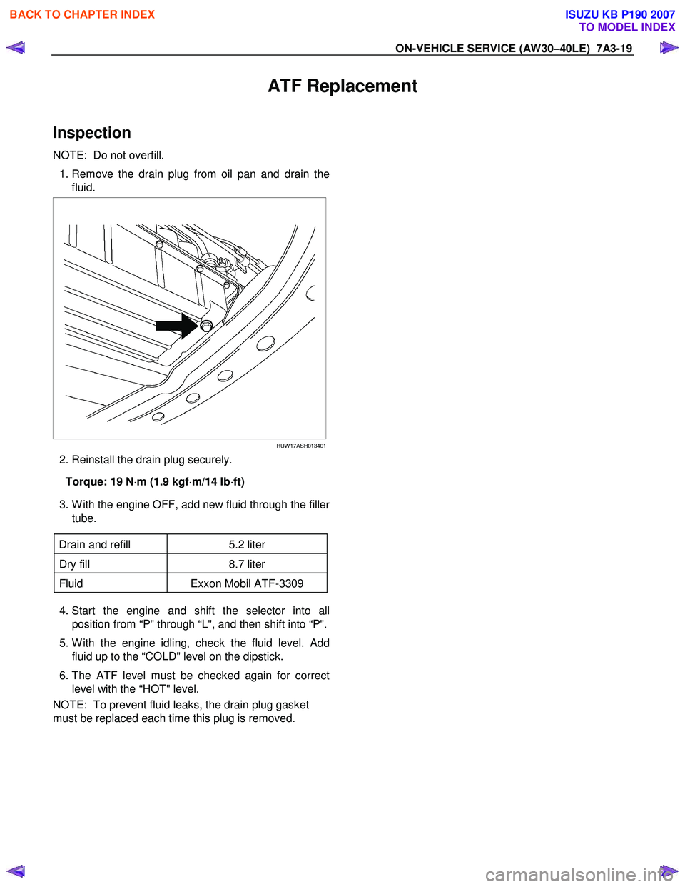
1. Remove the drain plug from oil pan and drain the
fluid.
RUW 17ASH013401
2. Reinstall the drain plug securely.
Torque: 19 N ⋅
⋅⋅
⋅
m (1.9 kgf ⋅
⋅⋅
⋅
m/14 Ib ⋅
⋅⋅
⋅
ft)
3. W ith the engine OFF, add new fluid through the fille
r
tube.
Drain and refill 5.2 liter
Dry fill 8.7 liter
Fluid Exxon Mobil ATF-3309
4. Start the engine and shift the selector into all
position from “P" through “L", and then shift into “P".
5. W ith the engine idling, check the fluid level. Add fluid up to the “COLD" level on the dipstick.
6. The ATF level must be checked again for correct level with the “HOT" level.
NOTE: To prevent fluid leaks, the drain plug gasket
must be replaced each time this plug is removed.
BACK TO CHAPTER INDEX
TO MODEL INDEX
ISUZU KB P190 2007
Page 4111 of 6020
7A3-26 ON-VEHICLE SERVICE (AW30–40LE)
Remove or Disconnect
1. Block the wheels.
2. Disconnect the negative battery cable.
3. Remove the rear console and the front console.
4. Remove the 2 screws fixing the select lever knob.
5. Remove the knob together with the knob button and spring from the lever.
6. Turn the sleeve counterclockwise to remove it. Make a note of the number of turns required to free
the sleeve.
7. Remove the harness connectors from the base plate.
8. Remove the upper housing (held in place by 4 latched fasteners).
9. Remove the lamp assembly by turning it counterclockwise.
10. Remove the spring plate.
11. Remove the grooved pin.
12. Disconnect the shift cable from the select lever.
13. Remove the lever assembly by pressing the rod down (lever in N position).
14. Remove the harness connectors from the shift lock unit, then remove the shift lock unit.
15. Remove the interlock controller.
16. If the replacement of shift lock release button o
r
shift lock button spring is required, remove the
position indicator housing, the shift lock button
spring and shift lock release button can be
removed.
Install or Connect
NOTE
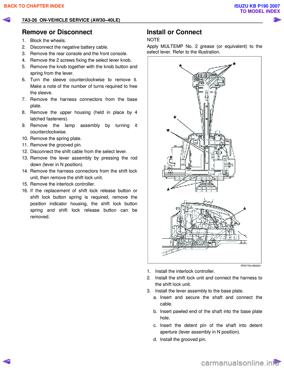
Apply MULTEMP No. 2 grease (or equivalent) to the
select lever. Refer to the illustration.
RTW 77ALH000201
1. Install the interlock controller.
2. Install the shift lock unit and connect the harness to the shift lock unit.
3. Install the lever assembly to the base plate. a. Insert and secure the shaft and connect the cable.
b. Insert pawled end of the shaft into the base plate hole.
c. Insert the detent pin of the shaft into detent aperture (lever assembly in N position).
d. Install the grooved pin.
BACK TO CHAPTER INDEX
TO MODEL INDEX
ISUZU KB P190 2007
Page 4112 of 6020
ON-VEHICLE SERVICE (AW30–40LE) 7A3-27
4. Install the spring plate.
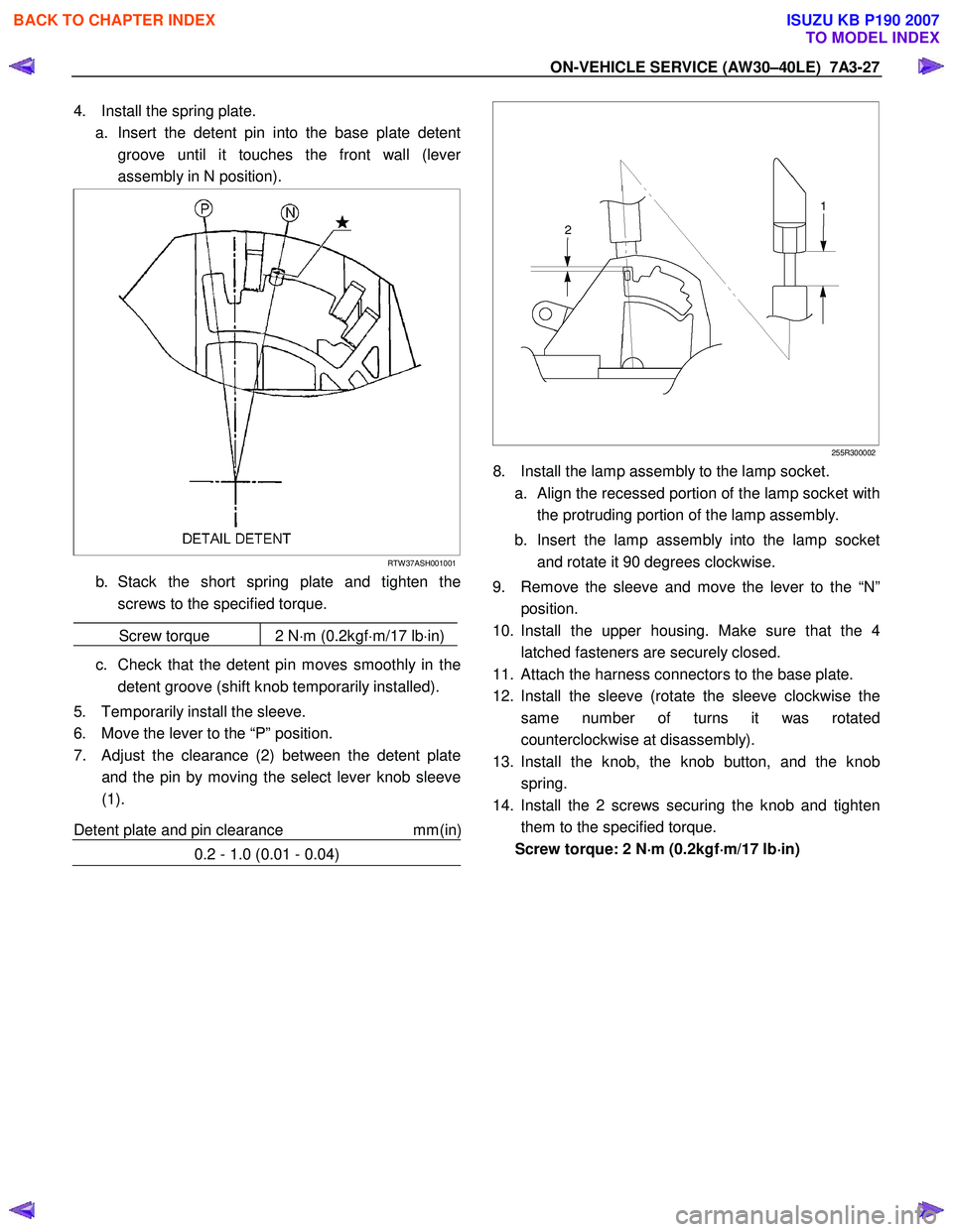
a. Insert the detent pin into the base plate detent groove until it touches the front wall (leve
r
assembly in N position).
RTW 37ASH001001
b. Stack the short spring plate and tighten thescrews to the specified torque.
Screw torque 2 N ⋅m (0.2kgf ⋅m/17 lb ⋅in)
c. Check that the detent pin moves smoothly in the
detent groove (shift knob temporarily installed).
5. Temporarily install the sleeve.
6. Move the lever to the “P” position.
7. Adjust the clearance (2) between the detent plate and the pin by moving the select lever knob sleeve
(1).
Detent plate and pin clearance mm(in
)
0.2 - 1.0 (0.01 - 0.04)
255R300002
8. Install the lamp assembly to the lamp socket.
a.
Align the recessed portion of the lamp socket with
the protruding portion of the lamp assembly.
b. Insert the lamp assembly into the lamp socket and rotate it 90 degrees clockwise.
9. Remove the sleeve and move the lever to the “N” position.
10. Install the upper housing. Make sure that the 4 latched fasteners are securely closed.
11. Attach the harness connectors to the base plate.
12. Install the sleeve (rotate the sleeve clockwise the same number of turns it was rotated
counterclockwise at disassembly).
13. Install the knob, the knob button, and the knob spring.
14. Install the 2 screws securing the knob and tighten them to the specified torque.
Screw torque: 2 N ⋅
⋅⋅
⋅
m (0.2kgf ⋅
⋅⋅
⋅
m/17 lb ⋅
⋅⋅
⋅
in)
BACK TO CHAPTER INDEX
TO MODEL INDEX
ISUZU KB P190 2007
Page 4114 of 6020

ON-VEHICLE SERVICE (AW30–40LE) 7A3-29
Install or Connect
1. Install the shift cable toward the inside of the cabin
from the bottom of the vehicle.
2. Push the shift cable into the select lever base.
3. Connect the shift cable to the select lever.
4. Fix the shift cable to the bracket.
Install the clip on the marking of shift cable.
5. Check that the select lever is in the “N” position.
6. Check that the transmission is in the “N” position.
249R300002
7. Slide the cover in the direction shown by the arrow
(1).
8. Use an ordinary screwdriver to move the lock piece
from the position indicated by the arrow (2). Continue
to move the lock piece until the adjuster position
begins to change.
P1010012
9. Connect the shift cable to the manual shaft select
lever at the transmission side.
10. Insert the lock piece to the adjuster (cable length
adjustment).
11. Slide the cover on the adjuster and secure lock
piece.
P1010016-2
11. Press the select lever knob button 5 times.
Then check that the select lever moves smoothly to each of its positions.
13. Check that the shift position indicated by the select
lever and the actual shift position are the same.
14. Install the front console and rear console.
15. Connect the negative battery cable.
16. Remove the wheel blocks.
BACK TO CHAPTER INDEX
TO MODEL INDEX
ISUZU KB P190 2007
Page 4270 of 6020

CONSTRUCTION AND FUNCTION 7A1-31
As a result, the lock-up piston is fitted slowly to the converter cover under pressure securing smooth lock-
up engagement.
Figure 51. Lock-up Control
DIRECT ELECTRIC SHIFT CONTROL (DESC)
Feature
• Based on each switch signal (low & reverse brake pressure, 2-4 brake pressure & high clutch pressure)
and each sensor signal (turbine sensor, speed sensor, engine speed signal & APP position signal), the
duty cycle type solenoid adjusts the clutch pressure to match the engine load and vehicle travel
conditions. Controlling the engagement and disengagement of the clutch and brake pressure is directly
and accurately controlled via TCM, which is different to the previous accumulator type.
Operation
• Instead of the previous system (on/off type of shift solenoid and shift valve), the combination of the duty
cycle type solenoid and the amplifier (Amp) valve are used to adjust the clutch pressure to match the
engine load and vehicle travel conditions, based on the signal from the TCM. Also, the pressure switch
provided in the oil passage of the control valve transmits the oil pressure condition (at that time) to TCM,
enabling the engagement and disengagement control of the clutch and brake to be directly and finely
carried out.
• When the gear is shifted from the 2nd to 3rd, 3rd to 4th (O/D), 4th (O/D) to 3rd and 3rd to 2nd, the clutch
pressures on the engagement side and disengagement side are simultaneously controlled.
As a result, engine racing or clutch drag is prevented which enables a smooth and quick shift response.
BACK TO CHAPTER INDEX
TO MODEL INDEX
ISUZU KB P190 2007
Page 4336 of 6020
7A2-52 TRANSMISSION CONTROL SYSTEM (JR405E)
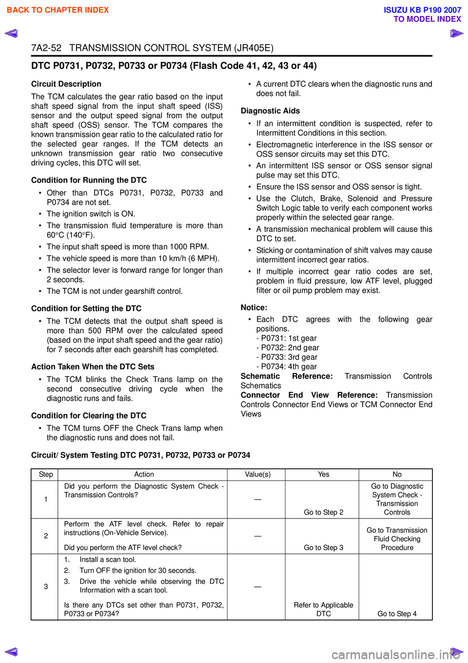
DTC P0731, P0732, P0733 or P0734 (Flash Code 41, 42, 43 or 44)
Circuit Description
The TCM calculates the gear ratio based on the input
shaft speed signal from the input shaft speed (ISS)
sensor and the output speed signal from the output
shaft speed (OSS) sensor. The TCM compares the
known transmission gear ratio to the calculated ratio for
the selected gear ranges. If the TCM detects an
unknown transmission gear ratio two consecutive
driving cycles, this DTC will set.
Condition for Running the DTC • Other than DTCs P0731, P0732, P0733 and P0734 are not set.
• The ignition switch is ON.
• The transmission fluid temperature is more than 60 °C (140 °F).
• The input shaft speed is more than 1000 RPM.
• The vehicle speed is more than 10 km/h (6 MPH).
• The selector lever is forward range for longer than 2 seconds.
• The TCM is not under gearshift control.
Condition for Setting the DTC • The TCM detects that the output shaft speed is more than 500 RPM over the calculated speed
(based on the input shaft speed and the gear ratio)
for 7 seconds after each gearshift has completed.
Action Taken When the DTC Sets • The TCM blinks the Check Trans lamp on the second consecutive driving cycle when the
diagnostic runs and fails.
Condition for Clearing the DTC • The TCM turns OFF the Check Trans lamp when the diagnostic runs and does not fail. • A current DTC clears when the diagnostic runs and
does not fail.
Diagnostic Aids • If an intermittent condition is suspected, refer to Intermittent Conditions in this section.
• Electromagnetic interference in the ISS sensor or OSS sensor circuits may set this DTC.
• An intermittent ISS sensor or OSS sensor signal pulse may set this DTC.
• Ensure the ISS sensor and OSS sensor is tight.
• Use the Clutch, Brake, Solenoid and Pressure Switch Logic table to verify each component works
properly within the selected gear range.
• A transmission mechanical problem will cause this DTC to set.
• Sticking or contamination of shift valves may cause intermittent incorrect gear ratios.
• If multiple incorrect gear ratio codes are set, problem in fluid pressure, low ATF level, plugged
filter or oil pump problem may exist.
Notice: • Each DTC agrees with the following gear positions.
- P0731: 1st gear
- P0732: 2nd gear
- P0733: 3rd gear
- P0734: 4th gear
Schematic Reference: Transmission Controls
Schematics
Connector End View Reference: Transmission
Controls Connector End Views or TCM Connector End
Views
Circuit/ System Testing DTC P0731, P0732, P0733 or P0734
Step Action Value(s)Yes No
1 Did you perform the Diagnostic System Check -
Transmission Controls? —
Go to Step 2 Go to Diagnostic
System Check - Transmission Controls
2 Perform the ATF level check. Refer to repair
instructions (On-Vehicle Service).
Did you perform the ATF level check? —
Go to Step 3 Go to Transmission
Fluid Checking Procedure
3 1. Install a scan tool.
2. Turn OFF the ignition for 30 seconds.
3. Drive the vehicle while observing the DTC Information with a scan tool.
Is there any DTCs set other than P0731, P0732,
P0733 or P0734? —
Refer to Applicable DTC Go to Step 4
BACK TO CHAPTER INDEX
TO MODEL INDEX
ISUZU KB P190 2007
Page 4423 of 6020
TRANSMISSION CONTROL SYSTEM (JR405E) 7A2-139
Repair Instructions
Transmission Controls Module (TCM) Replacement
Description
The following A - C steps provide an overview
procedure to replace and reprogram a TCM. Each A -C
steps is explained further in this section.
A. Replace the old TCM with the new TCM.
B. Program the latest software and calibrations into the
new TCM using the Service Programming System
(SPS) if released. If not released, do not perform this
and skip to Step C.
C. Program the vehicle identification number (VIN) into
the TCM.
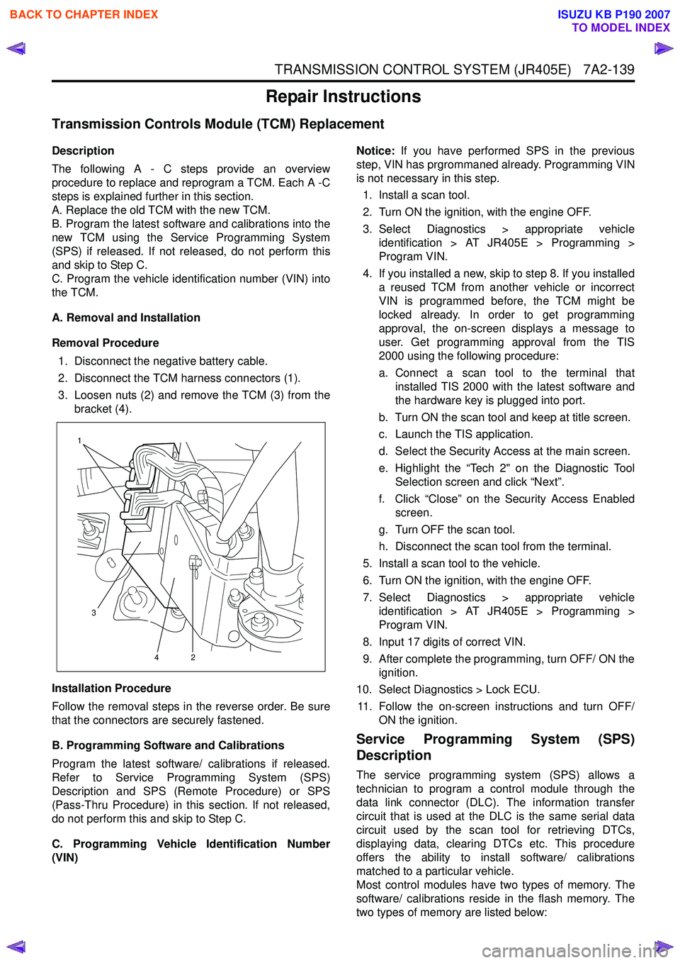
A. Removal and Installation
Removal Procedure 1. Disconnect the negative battery cable.
2. Disconnect the TCM harness connectors (1).
3. Loosen nuts (2) and remove the TCM (3) from the bracket (4).
Installation Procedure
Follow the removal steps in the reverse order. Be sure
that the connectors are securely fastened.
B. Programming Software and Calibrations
Program the latest software/ calibrations if released.
Refer to Service Programming System (SPS)
Description and SPS (Remote Procedure) or SPS
(Pass-Thru Procedure) in this section. If not released,
do not perform this and skip to Step C.
C. Programming Vehicle Identification Number
(VIN) Notice:
If you have performed SPS in the previous
step, VIN has prgrommaned already. Programming VIN
is not necessary in this step.
1. Install a scan tool.
2. Turn ON the ignition, with the engine OFF.
3. Select Diagnostics > appropriate vehicle identification > AT JR405E > Programming >
Program VIN.
4. If you installed a new, skip to step 8. If you installed a reused TCM from another vehicle or incorrect
VIN is programmed before, the TCM might be
locked already. In order to get programming
approval, the on-screen displays a message to
user. Get programming approval from the TIS
2000 using the following procedure:
a. Connect a scan tool to the terminal that installed TIS 2000 with the latest software and
the hardware key is plugged into port.
b. Turn ON the scan tool and keep at title screen.
c. Launch the TIS application.
d. Select the Security Access at the main screen.
e. Highlight the “Tech 2" on the Diagnostic Tool Selection screen and click “Next”.
f. Click “Close” on the Security Access Enabled screen.
g. Turn OFF the scan tool.
h. Disconnect the scan tool from the terminal.
5. Install a scan tool to the vehicle.
6. Turn ON the ignition, with the engine OFF.
7. Select Diagnostics > appropriate vehicle identification > AT JR405E > Programming >
Program VIN.
8. Input 17 digits of correct VIN.
9. After complete the programming, turn OFF/ ON the ignition.
10. Select Diagnostics > Lock ECU.
11. Follow the on-screen instructions and turn OFF/ ON the ignition.
Service Programming System (SPS)
Description
The service programming system (SPS) allows a
technician to program a control module through the
data link connector (DLC). The information transfer
circuit that is used at the DLC is the same serial data
circuit used by the scan tool for retrieving DTCs,
displaying data, clearing DTCs etc. This procedure
offers the ability to install software/ calibrations
matched to a particular vehicle.
Most control modules have two types of memory. The
software/ calibrations reside in the flash memory. The
two types of memory are listed below:
1
3 42
BACK TO CHAPTER INDEX
TO MODEL INDEX
ISUZU KB P190 2007