Page 4867 of 6020
TRANSFER CASE 7D-37
226R300005
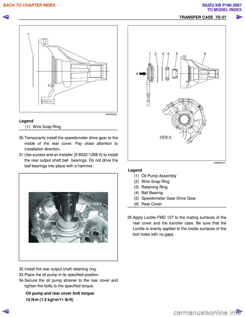
30. Temporarily install the speedometer drive gear to the
inside of the rear cover. Pay close attention to
installation direction.
31. Use a press and an installer (9-8522-1268-0) to install
the rear output shaft ball bearings. Do not drive the
ball bearings into place with a hammer.
32. Install the rear output shaft retaining ring.
33. Place the oil pump in its specified position.
34. Secure the oil pump strainer to the rear cover and
tighten the bolts to the specified torque.
Oil pump and rear cover bolt torque:
15 N ·m (1.5 kgf ·m/11 lb ·ft)
226R300010
35.
Apply Loctite FMD 127 to the mating surfaces of the
rear cover and the transfer case. Be sure that the
Loctite is evenly applied to the inside surfaces of the
bolt holes with no gaps.
Legend
(1) Oil Pump Assembly
(2) W ire Snap Ring
(3) Retaining Ring
(4) Ball Bearing
(5) Speedometer Gear Drive Gear
(6) Rear Cover
Legend
(1) W ire Snap Ring
BACK TO CHAPTER INDEX
TO MODEL INDEX
ISUZU KB P190 2007
Page 4868 of 6020
7D-38 TRANSFER CASE
226R300011
36. Install the rear cover to the transfer case and tighten
the bolts to the specified torque.
Rear cover and transfer case bolt torque:
22 N ·m (2.2 kgf ·m/16 lb ·ft)
37. Apply engine oil to the companion flange O-ring.
38. Install the O-ring to the front output shaft.
39. Secure the front companion flange with a flange
holder (5-8840-0133-0).
40. Install the end nuts and tighten them to the specified
torque.
Front companion flange end nut torque:
137 N ·m (14.0 kgf ·m/101 lb ·ft)
RTW 77DSH000201
41. Use a punch (5-8840-2293-0) to caulk the front
companion flange end nut.
226R300012
RUW 34DSH000301
Legend
(1) MAX 26mm (1.02 in)
(2) MIN 4mm (0.16 in)
42.
Apply Loctite 575 to the threaded portion of the
detente plugs.
BACK TO CHAPTER INDEX
TO MODEL INDEX
ISUZU KB P190 2007
Page 4923 of 6020
TRANSFER CONTROL SYSTEM 7D1-49
Step 4-3: (Same procedure as the step 3-3)
Stop the vehicle (close the accelerator and decrease the engine speed to L4: 3000rpm V6: 2000rpm or below).
(In case of AT): Set the transmission select lever to the N position.
(In case of MT): Set the transmission lever to the neutral position (stepping on the clutch lever is recommended).
Push the 4H button.
If shifting is not complete (indicator flashes at 2Hz), go to step 4-1.
5. When shifting from 4H or 4L to neutral
(Same procedure is required when shifting from 2H but in such a case, requirements for shifting from
2H to 4H are also applied.)
5-1 Neutral indicator continues flashing at 2Hz The neutral indicator continues flashing at 2Hz until 4H (4L) is completely separated in the transfer. If torsional
torque has accumulated between the transmission and road surface, separation may be difficult.
Step 5-1:
If the operation is not complete, execute step 7 for confirmation.
(In case of AT): Set the transmission select lever to the D position. After confirming that the gears are at the neutral position, return the lever to the N
position.
(In case of MT): Set the transmission lever to a vehicle running position and engage the clutch gently. After confirming that the gears are at the neutral position, return the lever to the
neutral position
5-2 When the neutral indicator flashes at 4Hz
As in the case of shifting from 4L to 4H, restriction is imposed to the operation from 4L or 4H (including 2H). If
the transmission lever is at a running range and engine speed is high (L4: 3000rpm, V6: 2000rpm or more)
while the vehicle is running, operation from the 4L or 4H (including 2H) of the transfer to the neutral is
impossible (restriction on operation).
Step 5-2:
Stop the vehicle.
(In case of AT): Set the transmission select lever to the N (or P) position.
(In case of MT): Set the transmission lever to the neutral position (at this time, stepping on the clutch is recommended).
Keep pushing the 2H and 4L button for 10 seconds.
Follow the start procedure for confirmation. (Confirmation of drive force is not transferred; same as in
step 5-1)
After the confirmation, set the transmission to the neutral position in the case of MT or to the neutral
position in the case of AT.
BACK TO CHAPTER INDEX
TO MODEL INDEX
ISUZU KB P190 2007
Page 4947 of 6020
ELECTRICAL-BODY AND CHASSIS 8A-9
SPLICING WIRE
Open the Harness
If the harness is taped, remove the tape.
To avoid wire insulation damage, use a sewing “seam ripper”
(available from sewing supply stores) to cut open the harness.
If the harness has a black plastic conduit, simply pull out the
desired wire.
Cut the wire
Begin by cutting as little wire off the harness as possible.
You may need the extra length of wire later if you decide to cut
more wire off to change the location of a splice.
You may have to adjust splice locations to make certain that
each splice is at least 1-1/2” (40 mm) away from other splices,
harness branches, or connectors.
Strip the insulation
W hen replacing a wire, use a wire of the same size as the
original wire.
Check the stripped wire for nicks or cut strands.
If the wire is damaged, repeat the procedure on a new section
of wire.
The two stripped wire ends should be equal in length.
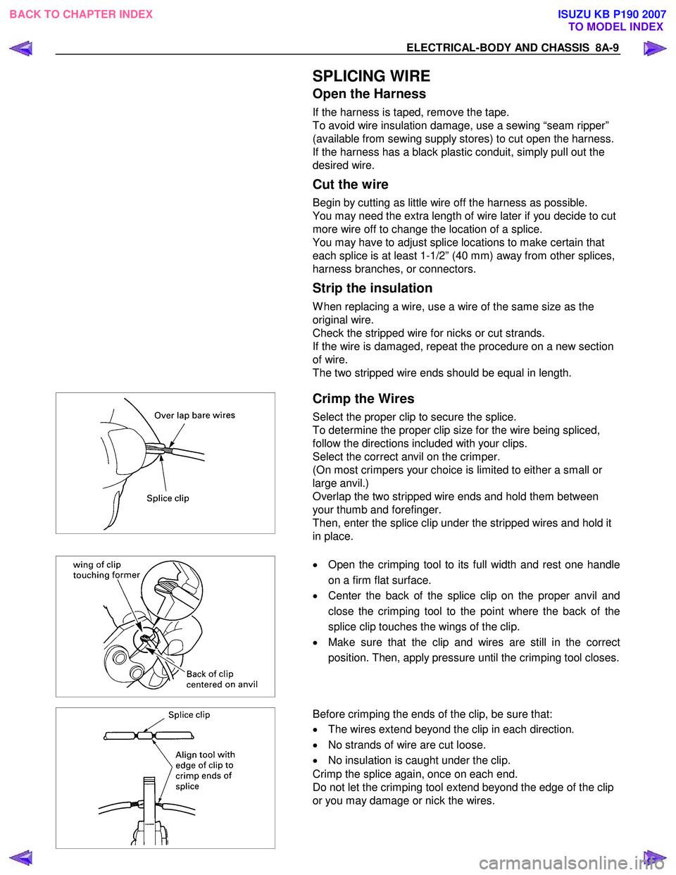
Crimp the Wires
Select the proper clip to secure the splice.
To determine the proper clip size for the wire being spliced,
follow the directions included with your clips.
Select the correct anvil on the crimper.
(On most crimpers your choice is limited to either a small or
large anvil.)
Overlap the two stripped wire ends and hold them between
your thumb and forefinger.
Then, enter the splice clip under the stripped wires and hold it
in place.
•
Open the crimping tool to its full width and rest one handle
on a firm flat surface.
• Center the back of the splice clip on the proper anvil and
close the crimping tool to the point where the back of the
splice clip touches the wings of the clip.
• Make sure that the clip and wires are still in the correct
position. Then, apply pressure until the crimping tool closes.
Before crimping the ends of the clip, be sure that:
• The wires extend beyond the clip in each direction.
• No strands of wire are cut loose.
• No insulation is caught under the clip.
Crimp the splice again, once on each end.
Do not let the crimping tool extend beyond the edge of the clip
or you may damage or nick the wires.
BACK TO CHAPTER INDEX TO MODEL INDEXISUZU KB P190 2007
Page 4950 of 6020
8A-12 ELECTRICAL-BODY AND CHASSIS
ABBREVIATIONS
Abbreviation Meaning of abbreviation Abbreviation Meaning of abbreviation
A Ampere (S) kW Kilowatt
ABS Anti-lock brake system LH Left hand
ASM Assembly LW B Long wheel base
AC Alternating current MPI Multipart fuel injection
A/C Air conditioner M/T Manual transmission
ACC Accessories PA Passenger
CARB Carburetor PIM Power train interface module
C/B Circuit breaker PJT Projector
CKP Crankshaft position QOS Quick On Start system
CSD Cold start device RH Right hand
DIS Direct ignition system RR Rear
DR Driver RW AL Rear wheel anti-lock brake system
DRM Data Recording Module SCV Suction control valve
EHCU Electronic Hydraulic control Unit SRS Supplemental restraint system
ECGI Electronic control gasoline injection ST Start
ECM Engine control module STD Standard
ECU Electronic control unit SW Switch
EFE Early fuel evaporation SW B Short wheel base
EGR Exhaust gas recirculation TCM Transmission control module
2W D Two-wheel drive TCCM Transfer case control module
4W D Four-wheel drive V Volt
FL Fusible link VSV Vacuum switching valve
FRT Front W W att (S)
H/L Headlight W OT W ide open throttle
W/ With HVAC
Heater, Ventilation, and Air
Conditioning W /O W ithout
IC Integrated circuit W /S W eld Splice
IG Ignition
BACK TO CHAPTER INDEX
TO MODEL INDEXISUZU KB P190 2007
Page 4971 of 6020
ELECTRICAL-BODY AND CHASSIS 8A-33
FUSE LOCATION
RHD/LHD
FUSE
NO. Capacity Indication on label NO. Capacity Indication on label
C 1 10A STARTER C 1110A AUDIO
C2
C
12 20A CIGAR/ACC SOCKET
10A TRAILER *3 C 13 15A AUDIO (+B)
C3 10A ELEC IG C 14 10A METER
C4 10A TURN C 15 15A STOP
C5 10A ABS/4WD C 16
C6 10A ENGINE C 17 10A ROOM
10A ECU *4 C19 10A METER (+B)
C7 15A TCM/IG COIL/ C2 120A DOOR LOCK
10A GLOW ENGINE *4 C22
C8 10A SRS 10A ANTI THEFT *5
C9 20A FRT WIPER
C10 15A BACKUP
SLOW BLOW FUSE
NO. Capacity Indication on label
C 18 20A RR DEF
C20 30A POWER WINDOW
FUSE BOX
*3 … HFV6 (AUSTRALIA)
*4 … HFV6
*5 … 4JJ 1-TC (EUROPE)
BACK TO CHAPTER INDEX
TO MODEL INDEXISUZU KB P190 2007
Page 5078 of 6020
8A-140 ELECTRICAL-BODY AND CHASSIS
REMOVAL AND INSTALLATION
ECM (ENGINE CONTROL MODULE);
C24SE
Removal
1. Lift both the ECM harness connector locking levers and
remove the two harness connectors form the ECM.
2. Remove the four socket head screws securing the ECM to the mounting bracket.
3. Remove the ECM from the engine compartment .
4. Pull out the ECM.
5. Disconnect both red and tan connectors.
Refer to the Section 6E-ENGINE of this Manual.
IMPORTANT: The replacement ECM must be programmed.
“SPS (Service Programming System) and immobilizer
programming (if equipped) is/are necessary”
Installation
Follow the removal procedure in the reverse order to install the
ECM.
Pay close attention to the important points mentioned in the
following paragraphs.
Connector
Be absolutely sure that ECM is securely connected.
This will prevent a poor contact and open circuit.
BACK TO CHAPTER INDEX TO MODEL INDEXISUZU KB P190 2007
Page 5079 of 6020
ELECTRICAL-BODY AND CHASSIS 8A-141
REMOVAL AND INSTALLATION
ECM (ENGINE CONTROL MODULE);
4JH1-TC
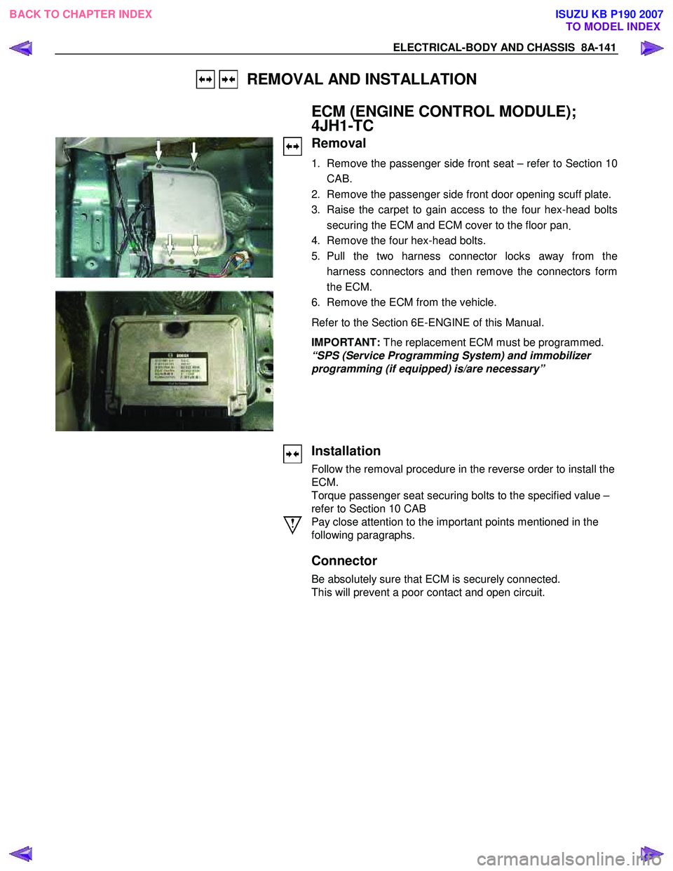
Removal
1. Remove the passenger side front seat – refer to Section 10
CAB.
2. Remove the passenger side front door opening scuff plate.
3. Raise the carpet to gain access to the four hex-head bolts securing the ECM and ECM cover to the floor pan .
4. Remove the four hex-head bolts.
5. Pull the two harness connector locks away from the harness connectors and then remove the connectors form
the ECM.
6. Remove the ECM from the vehicle.
Refer to the Section 6E-ENGINE of this Manual.
IMPORTANT: The replacement ECM must be programmed.
“SPS (Service Programming System) and immobilizer
programming (if equipped) is/are necessary”
Installation
Follow the removal procedure in the reverse order to install the
ECM.
Torque passenger seat securing bolts to the specified value –
refer to Section 10 CAB
Pay close attention to the important points mentioned in the
following paragraphs.
Connector
Be absolutely sure that ECM is securely connected.
This will prevent a poor contact and open circuit.
BACK TO CHAPTER INDEX TO MODEL INDEXISUZU KB P190 2007