2007 ISUZU KB P190 ECU
[x] Cancel search: ECUPage 5522 of 6020
8A-584 ELECTRICAL-BODY AND CHASSIS
RTW 38DLH000101
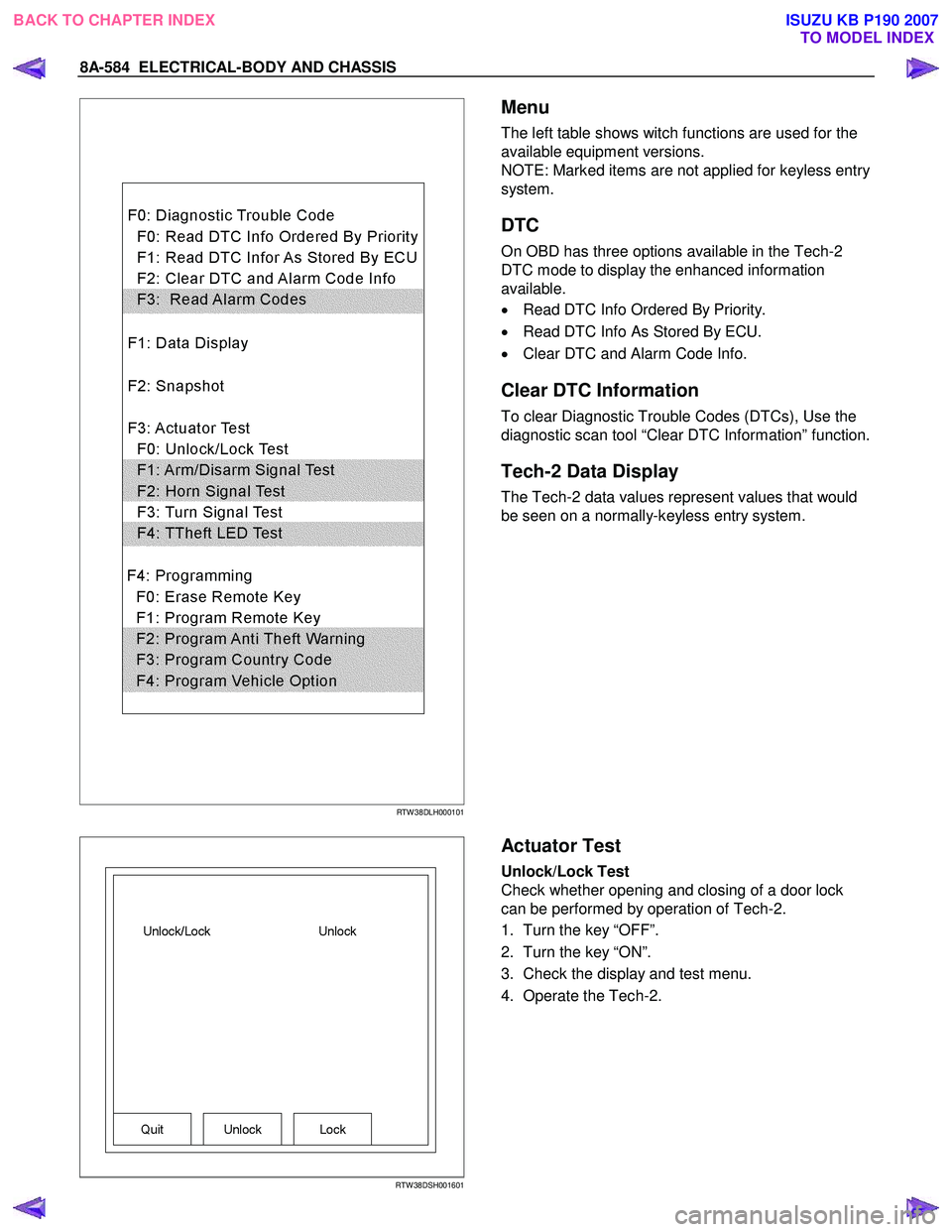
Menu
The left table shows witch functions are used for the
available equipment versions.
NOTE: Marked items are not applied for keyless entry
system.
DTC
On OBD has three options available in the Tech-2
DTC mode to display the enhanced information
available.
• Read DTC Info Ordered By Priority.
• Read DTC Info As Stored By ECU.
• Clear DTC and Alarm Code Info.
Clear DTC Information
To clear Diagnostic Trouble Codes (DTCs), Use the
diagnostic scan tool “Clear DTC Information” function.
Tech-2 Data Display
The Tech-2 data values represent values that would
be seen on a normally-keyless entry system.
RTW 38DSH001601
Actuator Test
Unlock/Lock Test
Check whether opening and closing of a door lock
can be performed by operation of Tech-2.
1. Turn the key “OFF”.
2. Turn the key “ON”.
3. Check the display and test menu.
4. Operate the Tech-2.
BACK TO CHAPTER INDEX TO MODEL INDEXISUZU KB P190 2007
Page 5523 of 6020
ELECTRICAL-BODY AND CHASSIS 8A-585
RTW 38DSH001701
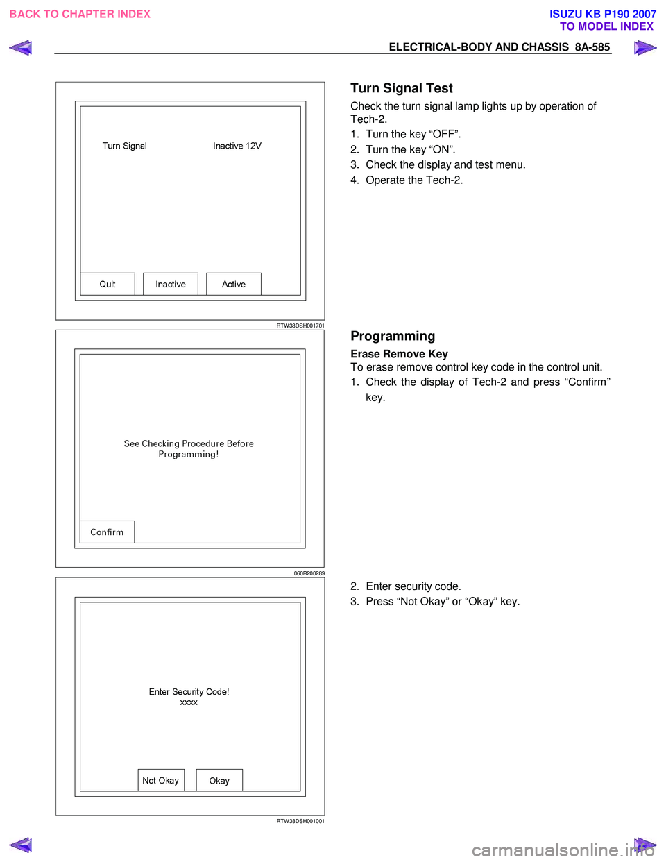
Turn Signal Test
Check the turn signal lamp lights up by operation of
Tech-2.
1. Turn the key “OFF”.
2. Turn the key “ON”.
3. Check the display and test menu.
4. Operate the Tech-2.
060R200289
Programming
Erase Remove Key
To erase remove control key code in the control unit.
1. Check the display of Tech-2 and press “Confirm”
key.
RTW 38DSH001001
2. Enter security code.
3. Press “Not Okay” or “Okay” key.
BACK TO CHAPTER INDEX TO MODEL INDEXISUZU KB P190 2007
Page 5578 of 6020

8B-6 CRUISE CONTROL SYSTEM
Cruise Control Main Switch
Removal
1. Disconnect the battery ground cable.
RTW 78ASH001801
2. Remove the side ventilation grille 1.
RTW 78ASH002301
3. Disconnect the switch connector and push the lock from the
backside of the side ventilation grille to remove the cruise
control main switch.
Installation
To install, follow the removal procedure in reverse order, noting
the following point.
1. Push in the switch with your fingers until it locks securely.
Cruise Control Switch (Combination Switch)
Removal and Installation
Refer to the Lighting Switch (Combination Switch) removal and
installation procedure of Lighting in Body and Chassis section.
BACK TO CHAPTER INDEX TO MODEL INDEXISUZU KB P190 2007
Page 5662 of 6020
SUPPLEMENTAL RESTRAINT SYSTEM 9A-27
5. Remove the passenger air bag assembly from the
vehicle. Refer to “Passenger Air Bag Assembl
y
Removal “.
6. Clear a space on the ground approximately 183 cm (six feet) in diameter where the fixture with
attached air bag assembly is to be placed fo
r
deployment. A paved outdoor location where there
is no activity is preferred. If an outdoor location is
not available, a space on the shop floor where
there is no activity and there is sufficient ventilation
is recommended. Ensure that no loose o
r
flammable objects are within the deployment area.
7. Place the 5-8840-2420-0 on the bench vise. This is necessary to provide sufficient stabilization o
f
the fixture during deployment.
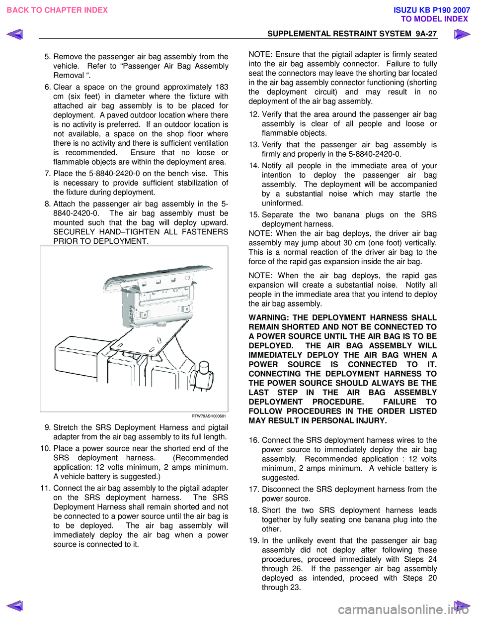
8. Attach the passenger air bag assembly in the 5- 8840-2420-0. The air bag assembly must be
mounted such that the bag will deploy upward.
SECURELY HAND–TIGHTEN ALL FASTENERS
PRIOR TO DEPLOYMENT.
RTW 79ASH000601
9. Stretch the SRS Deployment Harness and pigtail
adapter from the air bag assembly to its full length.
10. Place a power source near the shorted end of the SRS deployment harness. (Recommended
application: 12 volts minimum, 2 amps minimum.
A vehicle battery is suggested.)
11. Connect the air bag assembly to the pigtail adapte
r
on the SRS deployment harness. The SRS
Deployment Harness shall remain shorted and not
be connected to a power source until the air bag is
to be deployed. The air bag assembly will
immediately deploy the air bag when a powe
r
source is connected to it.
NOTE: Ensure that the pigtail adapter is firmly seated
into the air bag assembly connector. Failure to full
y
seat the connectors may leave the shorting bar located
in the air bag assembly connector functioning (shorting
the deployment circuit) and may result in no
deployment of the air bag assembly.
12. Verify that the area around the passenger air bag assembly is clear of all people and loose o
r
flammable objects.
13. Verify that the passenger air bag assembly is firmly and properly in the 5-8840-2420-0.
14. Notify all people in the immediate area of you
r
intention to deploy the passenger air bag
assembly. The deployment will be accompanied
by a substantial noise which may startle the
uninformed.
15. Separate the two banana plugs on the SRS deployment harness.
NOTE: W hen the air bag deploys, the driver air bag
assembly may jump about 30 cm (one foot) vertically.
This is a normal reaction of the driver air bag to the
force of the rapid gas expansion inside the air bag.
NOTE: W hen the air bag deploys, the rapid gas
expansion will create a substantial noise. Notify all
people in the immediate area that you intend to deplo
y
the air bag assembly.
WARNING: THE DEPLOYMENT HARNESS SHALL
REMAIN SHORTED AND NOT BE CONNECTED TO
A POWER SOURCE UNTIL THE AIR BAG IS TO BE
DEPLOYED. THE AIR BAG ASSEMBLY WILL
IMMEDIATELY DEPLOY THE AIR BAG WHEN
A
POWER SOURCE IS CONNECTED TO IT.
CONNECTING THE DEPLOYMENT HARNESS TO
THE POWER SOURCE SHOULD ALWAYS BE THE
LAST STEP IN THE AIR BAG ASSEMBLY
DEPLOYMENT PROCEDURE. FAILURE TO
FOLLOW PROCEDURES IN THE ORDER LISTED
MAY RESULT IN PERSONAL INJURY.
16. Connect the SRS deployment harness wires to the power source to immediately deploy the air bag
assembly. Recommended application : 12 volts
minimum, 2 amps minimum. A vehicle battery is
suggested.
17. Disconnect the SRS deployment harness from the power source.
18. Short the two SRS deployment harness leads together by fully seating one banana plug into the
other.
19. In the unlikely event that the passenger air bag assembly did not deploy after following these
procedures, proceed immediately with Steps 24
through 26. If the passenger air bag assembl
y
deployed as intended, proceed with Steps 20
through 23.
BACK TO CHAPTER INDEX TO MODEL INDEXISUZU KB P190 2007
Page 5664 of 6020
SUPPLEMENTAL RESTRAINT SYSTEM 9A-29
5. Strip 13 mm (1/2 inch) of insulation from the yellow
– green and yellow – black wire lead of the
connector.
6. Cut two 900 cm (30 feet) deployment wires from 0.8 mm
2 (18 gauge) or thicker multi–strand wire.
These wires will be used to fabricate the drive
r
deployment harness.
7. Strip 13 mm (1/2 inch) of insulation from both ends of the wires cut in the previous step.
8. Short the wires by twisting together one end from each. Deployment wires shall remain shorted and
not be connected to a power source until the ai
r
bag is to be deployed.
WARNING: FAILURE TO FOLLOW PROCEDURES
IN THE ORDER LISTED COULD RESULT IN
PERSONAL INJURY. NEVER CONNECT
DEPLOYMENT WIRES TO ANY POWER SOURCE
BEFORE CONNECTING DEPLOYMENT WIRES TO
THE AIR BAG ASSEMBLY LEADS. DEPLOYMENT
WIRES SHALL REMAIN SHORTED AND NOT BE
CONNECTED TO A POWER SOURCE UNTIL THE
AIR BAG IS TO BE DEPLOYED. THE AIR BAG
ASSEMBLY WILL IMMEDIATELY DEPLOY THE AIR
BAG WHEN A POWER SOURCE IS CONNECTED
TO IT. WEAR SAFETY GLASSES THROUGHOUT
THIS ENTIRE DEPLOYMENT AND DISPOSAL
PROCEDURE.
9. Twist together one connector wire lead to one deployment wire. The connection should be
mechanically secure.
10. Bend the twisted connection made in the previous step flat and wrap it tightly with electrical tape to
insulate and secure.
11. Twist together, bend and tape the remaining connector wire lead to the remaining deployment
wire.
12. Connect the deployment harness to the driver ai
r
bag assembly yellow connector at the base of the
steering column. Route the deployment harness
out through the driver’s side of the vehicle.
WARNING: DEPLOYMENT WIRES SHALL REMAIN
SHORTED AND NOT BE CONNECTED TO
A
POWER SOURCE UNTIL THE AIR BAG IS TO BE
DEPLOYED.
THE AIR BAG ASSEMBLY WILL IMMEDIATELY
DEPLOY THE AIR BAG WHEN A POWER SOURCE
IS CONNECTED TO IT.
Connecting the deployment wires to the powe
r
source should always be the final step in the ai
r
bag assembly deployment procedure.
Failure to follow procedures in the order listed
could result in personal injury.
13. Disconnect the passenger air bag assembly yello
w
connector located behind the glove box assembly.
14. Cut the passenger air bag assembly harness
connector from the vehicle leaving at least 15 cm
(six inches) of wire at the connector.
15. Strip 13 mm (1/2 inch) of insulation from the blue– white and pink–blue wire lead of the connector.
16. Cut two 900 cm (30 feet) deployment wires from 0.8 mm
2 (18 gauge) or thicker multi–strand wire.
These wires will be used to fabricate the
passenger deployment harness.
17. Strip 13 mm (1/2 inch) of insulation from both ends of the wires cut in the previous step.
18. Short the wires by twisting together one end from each. The deployment wires shall remain shorted
and not be connected to a power source until the
air bag is to be deployed.
WARNING: FAILURE TO FOLLOW PROCEDURES
IN THE ORDER LISTED COULD RESULT IN
PERSONAL INJURY. NEVER CONNECT
DEPLOYMENT WIRES TO ANY POWER SOURCE
BEFORE CONNECTING DEPLOYMENT WIRES TO
THE AIR BAG ASSEMBLY LEADS. DEPLOYMENT
WIRES SHALL REMAIN SHORTED AND NOT BE
CONNECTED TO A POWER SOURCE UNTIL THE
AIR BAG IS TO BE DEPLOYED. THE AIR BAG
ASSEMBLY WILL IMMEDIATELY DEPLOY THE AIR
BAG WHEN A POWER SOURCE IS CONNECTED
TO IT. WEAR SAFETY GLASSES THROUGHOUT
THIS ENTIRE DEPLOYMENT AND DISPOSAL
PROCEDURE.
19. Twist together one connector wire lead to one deployment wire. The connection should be
mechanically secure.
20. Bend the twisted connection made in the previous step flat and wrap it tightly with electrical tape to
insulate and secure.
21. Twist together, bend and tape the remaining connector wire lead to the remaining deployment
wire.
22. Connect the deployment harness to the passenge
r
air bag assembly yellow connector located behind
the glove box assembly. Route the deployment
harness out through the passenger side of the
vehicle.
WARNING: DEPLOYMENT WIRES SHALL REMAIN
SHORTED AND NOT BE CONNECTED TO
A
POWER SOURCE UNTIL THE AIR BAG IS TO BE
DEPLOYED. THE AIR BAG ASSEMBLY WILL
IMMEDIATELY DEPLOY THE AIR BAG WHEN
A
POWER SOURCE IS CONNECTED TO IT.
CONNECTING THE DEPLOYMENT WIRES
SHOULD ALWAYS BE THE FINAL STEP IN THE
AIR BAG ASSEMBLY DEPLOYMENT PROCEDURE.
FAILURE TO FOLLOW PROCEDURES IN THE
ORDER LISTED COULD RESULT IN PERSONAL
INJURY.
BACK TO CHAPTER INDEX TO MODEL INDEXISUZU KB P190 2007
Page 5695 of 6020
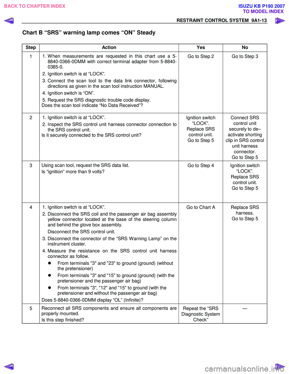
RESTRAINT CONTROL SYSTEM 9A1-13
Chart B “SRS” warning lamp comes “ON” Steady
Step Action Yes No
1
1. W hen measurements are requested in this chart use a 5-
8840-0366-0DMM with correct terminal adapter from 5-8840-
0385-0.
2. Ignition switch is at “LOCK”.
3. Connect the scan tool to the data link connector, following
directions as given in the scan tool instruction MANUAL.
4. Ignition switch is “ON”.
5. Request the SRS diagnostic trouble code display.
Does the scan tool indicate “No Data Received”? Go to Step 2 Go to Step 3
2
1. Ignition switch is at “LOCK”.
2. Inspect the SRS control unit harness connector connection to
the SRS control unit.
Is it securely connected to the SRS control unit? Ignition switch
“LOCK”.
Replace SRS control unit.
Go to Step 5 Connect SRS
control unit
securely to de–
activate shorting
clip in SRS control unit harness connector.
Go to Step 5
3 Using scan tool, request the SRS data list.
Is “ignition” more than 9 volts? Go to Step 4 Ignition switch
“LOCK”.
Replace SRS control unit.
Go to Step 5
4
1. Ignition switch is at “LOCK”.
2. Disconnect the SRS coil and the passenger air bag assembly
yellow connector located at the base of the steering column
and behind the glove box assembly.
Disconnect the SRS control unit.
3. Disconnect the connector of the “SRS W arning Lamp” on the
instrument cluster.
4. Measure the resistance on the SRS control unit harness connector as follow.
�z From terminals "3" and "23" to ground (ground) (without
the pretensioner)
�z From terminals "3" and "15" to ground (ground) (with the
pretensioner and the passenger air bag)
�z From terminals "3", "12" and "15" to ground (with the
pretensioner and without the passenger air bag)
Does 5-8840-0366-0DMM display “OL” (Infinite)? Go to Chart A Replace SRS
harness.
Go to Step 5
5 Reconnect all SRS components and ensure all components are
properly mounted.
Is this step finished? Repeat the “SRS
Diagnostic System Check” —
BACK TO CHAPTER INDEX
TO MODEL INDEX
ISUZU KB P190 2007
Page 5761 of 6020
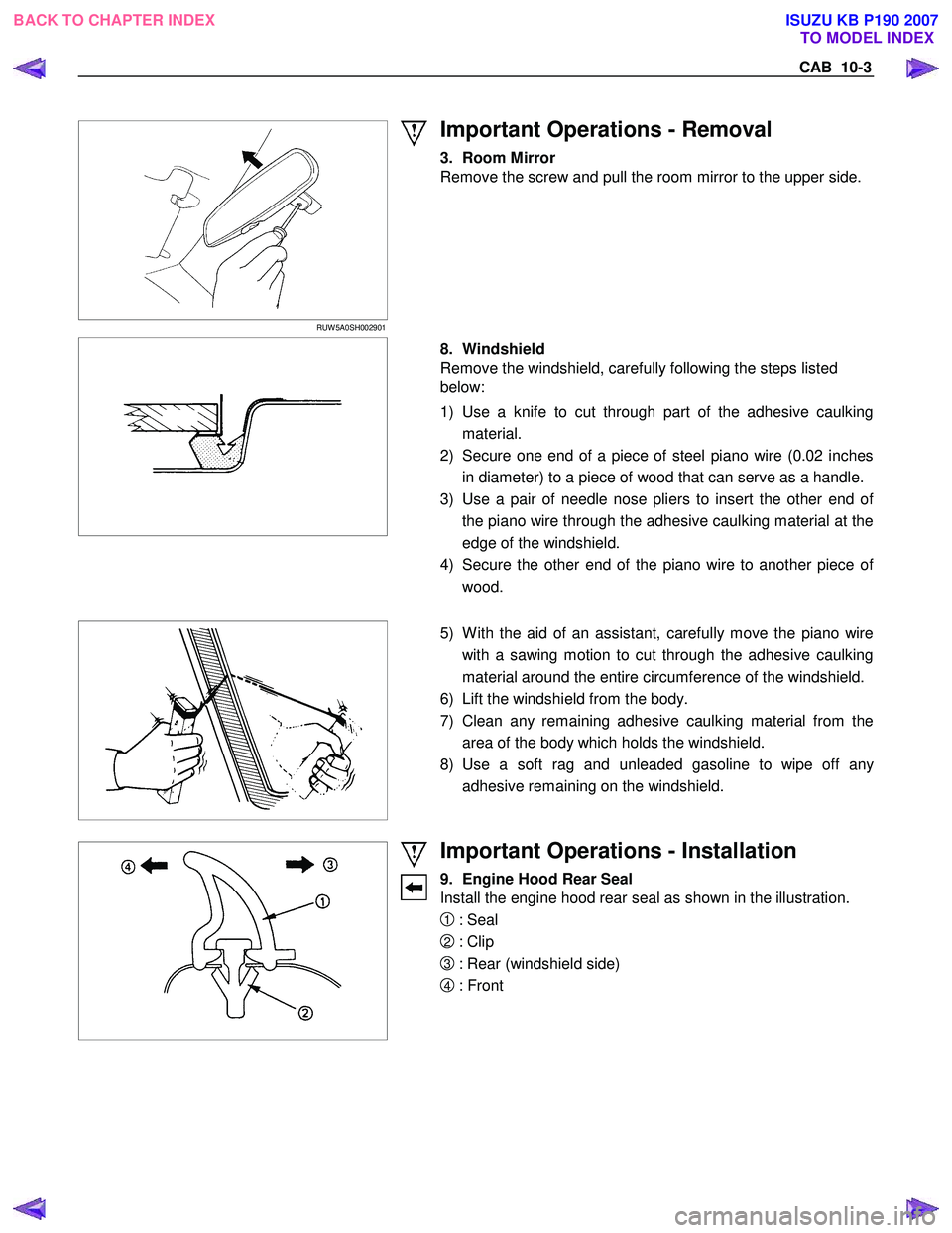
CAB 10-3
RUW 5A0SH002901
Important Operations - Removal
3. Room Mirror
Remove the screw and pull the room mirror to the upper side.
8. Windshield
Remove the windshield, carefully following the steps listed
below:
1) Use a knife to cut through part of the adhesive caulking material.
2) Secure one end of a piece of steel piano wire (0.02 inches in diameter) to a piece of wood that can serve as a handle.
3) Use a pair of needle nose pliers to insert the other end o
f
the piano wire through the adhesive caulking material at the
edge of the windshield.
4) Secure the other end of the piano wire to another piece o
f
wood.
5) W ith the aid of an assistant, carefully move the piano wire
with a sawing motion to cut through the adhesive caulking
material around the entire circumference of the windshield.
6) Lift the windshield from the body.
7) Clean any remaining adhesive caulking material from the area of the body which holds the windshield.
8) Use a soft rag and unleaded gasoline to wipe off an
y
adhesive remaining on the windshield.
Important Operations - Installation
9. Engine Hood Rear Seal
Install the engine hood rear seal as shown in the illustration.
1 : Seal
2 : Clip
3 : Rear (windshield side)
4 : Front
BACK TO CHAPTER INDEX TO MODEL INDEX
ISUZU KB P190 2007
Page 5765 of 6020
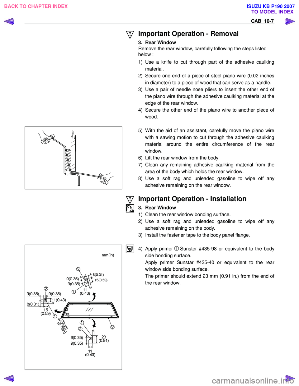
CAB 10-7
Important Operation - Removal
3. Rear Window
Remove the rear window, carefully following the steps listed
below :
1) Use a knife to cut through part of the adhesive caulking material.
2) Secure one end of a piece of steel piano wire (0.02 inches in diameter) to a piece of wood that can serve as a handle.
3) Use a pair of needle nose pliers to insert the other end o
f
the piano wire through the adhesive caulking material at the
edge of the rear window.
4) Secure the other end of the piano wire to another piece o
f
wood.
5) W ith the aid of an assistant, carefully move the piano wire
with a sawing motion to cut through the adhesive caulking
material around the entire circumference of the rea
r
window.
6) Lift the rear window from the body.
7) Clean any remaining adhesive caulking material from the area of the body which holds the rear window.
8) Use a soft rag and unleaded gasoline to wipe off an
y
adhesive remaining on the rear window.
Important Operation - Installation
3. Rear Window
1) Clean the rear window bonding surface.
2) Use a soft rag and unleaded gasoline to wipe off an
y
adhesive remaining on the body.
3) Install the fastener tape to the body panel flange.
4) Apply primer 1 Sunster #435-98 or equivalent to the body
side bonding surface.
Apply primer Sunstar #435-40 or equivalent to the rea
r
window side bonding surface.
The primer should extend 23 mm (0.91 in.) from the end o
f
the rear window.
BACK TO CHAPTER INDEX TO MODEL INDEX
ISUZU KB P190 2007