2007 ISUZU KB P190 ECU
[x] Cancel search: ECUPage 3961 of 6020
Automatic Transmission – 4L60E – On-vehicle Servicing Page 7C4–48
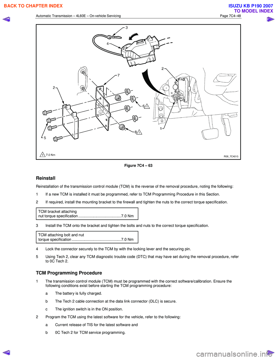
Figure 7C4 – 63
Reinstall
Reinstallation of the transmission control module (TCM) is the reverse of the removal procedure, noting the following:
1 If a new TCM is installed it must be programmed, refer to TCM Programming Procedure in this Section.
2 If required, install the mounting bracket to the firewall and tighten the nuts to the correct torque specification.
TCM bracket attaching
nut torque specification ........................................7.0 Nm
3 Install the TCM onto the bracket and tighten the bolts and nuts to the correct torque specification. TCM attaching bolt and nut
torque specification ..............................................7.0 Nm
4 Lock the connector securely to the TCM by with the locking lever and the securing pin.
5 Using Tech 2, clear any TCM diagnostic trouble code (DTC) that may have set during the removal procedure, refer to 0C Tech 2.
TCM Programming Procedure
1 The transmission control module (TCM) must be programmed with the correct software/calibration. Ensure the following conditions exist before starting the TCM programming procedure:
a The battery is fully charged.
b The Tech 2 cable connection at the data link connector (DLC) is secure.
c The ignition switch is in the ON position.
2 Program the TCM using the latest software for the vehicle, refer to the following: a Current release of TIS for the latest software and
b 0C Tech 2 for TCM service programming.
BACK TO CHAPTER INDEX
TO MODEL INDEX
ISUZU KB P190 2007
Page 3962 of 6020
Automatic Transmission – 4L60E – On-vehicle Servicing Page 7C4–49
3 If the TCM fails to program, proceed as follows:
a Ensure the TCM connection is secured.
b Ensure Tech 2 is programmed with the latest software version.
c Attempt to re-program the TCM. Replace the TCM if it still cannot be programmed properly.
BACK TO CHAPTER INDEX
TO MODEL INDEX
ISUZU KB P190 2007
Page 3988 of 6020
7A2-22 TRANSMISSION CONTROL SYSTEM (AW30–40LE)
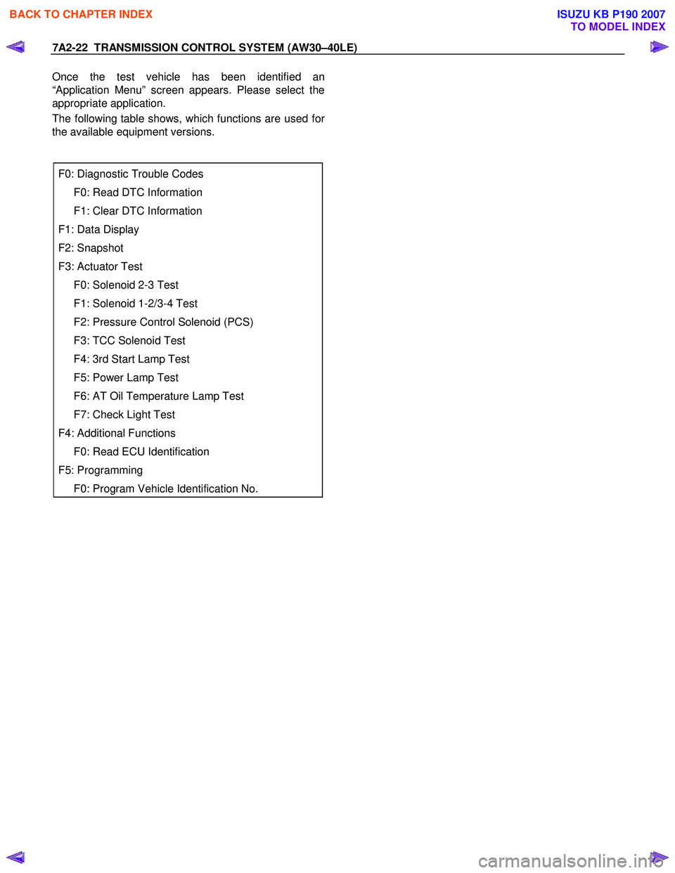
Once the test vehicle has been identified an
“Application Menu” screen appears. Please select the
appropriate application.
The following table shows, which functions are used fo
r
the available equipment versions.
F0: Diagnostic Trouble Codes
F0: Read DTC Information
F1: Clear DTC Information
F1: Data Display
F2: Snapshot
F3: Actuator Test
F0: Solenoid 2-3 Test
F1: Solenoid 1-2/3-4 Test
F2: Pressure Control Solenoid (PCS)
F3: TCC Solenoid Test
F4: 3rd Start Lamp Test
F5: Power Lamp Test
F6: AT Oil Temperature Lamp Test
F7: Check Light Test
F4: Additional Functions
F0: Read ECU Identification
F5: Programming
F0: Program Vehicle Identification No.
BACK TO CHAPTER INDEX
TO MODEL INDEX
ISUZU KB P190 2007
Page 3992 of 6020
![ISUZU KB P190 2007 Workshop Repair Manual 7A2-26 TRANSMISSION CONTROL SYSTEM (AW30–40LE)
Snapshot Display With TIS2000
Procedures for transferring and displaying Tech2
snapshot data by using TIS2000 [Snapshot Upload]
function ISUZU KB P190 2007 Workshop Repair Manual 7A2-26 TRANSMISSION CONTROL SYSTEM (AW30–40LE)
Snapshot Display With TIS2000
Procedures for transferring and displaying Tech2
snapshot data by using TIS2000 [Snapshot Upload]
function](/manual-img/61/57177/w960_57177-3991.png)
7A2-26 TRANSMISSION CONTROL SYSTEM (AW30–40LE)
Snapshot Display With TIS2000
Procedures for transferring and displaying Tech2
snapshot data by using TIS2000 [Snapshot Upload]
function is described below.
Snapshot data can be displayed with [Snapshot Upload]
function included in TIS2000.
By analyzing these data in various methods, trouble
conditions can be checked.
Snapshot data is displayed by executing the three steps
below shown:
1. Record the snapshot data, in Tech2.
2. Transfer the snapshot data to PC.
BACK TO CHAPTER INDEX
TO MODEL INDEX
ISUZU KB P190 2007
Page 4005 of 6020
TRANSMISSION CONTROL SYSTEM (AW30–40LE) 7A2-39
Diagnostic Trouble Code (DTC) Type
Definitions
Emission Related DTC
Action Taken When the DTC Sets - Type A
• The Engine Control Module (ECM) illuminates the
malfunction indicator lamp (MIL) when the
diagnostic runs and fails.
• The ECM records the operating conditions at the
time the diagnostic fails. The ECM stores this
information in the Freeze Frame/ Failure Records.
Action Taken When the DTC Sets - Type B
• The ECM illuminates the MIL on the second
consecutive driving cycle when the diagnostic runs
and fails.
• The ECM records the operating conditions at the
time the diagnostic fails, the ECM stores this
information in the Failure Records. If the
diagnostic reports a failure on the second
consecutive driving cycle, the ECM records the
operating conditions at the time of failure and
stores this information in the Freeze Frame and
updates the Failure Records.
Conditions for Clearing the MIL/ DTC - Type A o
r
Type B • The ECM turns OFF the MIL after 3 consecutive
driving cycles when the diagnostic runs and does
not fail. (Euro 4 Specification)
• The ECM turns OFF the MIL after 1 driving cycle
when the diagnostic runs and does not fail.
(Except Euro 4 Specification)
•
A current DTC clears when the diagnostic runs
and passes after 1 driving cycle.
• A history DTC clears after 40 consecutive warm-
up cycles, if no failures are reported.
• Use a scan tool to clear the MIL and the DTC.
Non-Emissions Related DTCs
Action Taken When the DTC Sets - Type C or Type
D
• The TCM illuminates the Check Trans lamp when
the diagnostic runs and fails.
• The TCM records the operating conditions at the
time the diagnostic fails. The TCM stores this
information in the Failure Records.
• The TCM illuminates the Check Trans on the
second consecutive driving cycle when the
diagnostic runs and fails.
• The TCM records the operating conditions at the
time the diagnostic fails, the TCM stores this
information in the Failure Records. If the
diagnostic reports a failure on the second
consecutive driving cycle, the TCM records the
operating conditions at the time of failure and
stores this information in the Freeze Frame and
updates the Failure Records.
Conditions for Clearing the Check Trans Lamp/ DTC
- Type C or Type D
• The TCM turns OFF the Check Trans lamp after 1
driving cycle when the diagnostic runs and does
not fail.
•
A current DTC clears when the diagnostic runs
and passes after 3 driving cycle.
• A history DTC clears after 40 consecutive warm-
up cycles, if no failures are reported.
• Use a scan tool to clear the Check Trans lamp and
the DTC.
Action Taken When the DTC Sets - Type E or Type F • The TCM will not illuminate the Check Trans lamp.
• The TCM records the operating conditions at the
time the diagnostic fails. The TCM stores this
information in the Failure Records.
Conditions for Clearing the DTC - Type E or Type F •
A current DTC clears when the diagnostic runs
and passes after 1 driving cycle.
• A history DTC clears after 40 consecutive warm-
up cycles, if no failures are reported.
• Use a scan tool to clear the DTC.
BACK TO CHAPTER INDEX
TO MODEL INDEX
ISUZU KB P190 2007
Page 4009 of 6020
TRANSMISSION CONTROL SYSTEM (AW30–40LE) 7A2-43
DTC P0602 (Flash Code 63)
Circuit Description
The Service Programming System (SPS) updates the
flash calibration files that are stored in a Transmission
Control Module (TCM). The calibration file
custom-tailors a module to a certain vehicle. The
calibration file contains data for things such as spark
curves and fuel control. W hen troubleshooting a
driveability problem, diagnosis may call fo
r
reprogramming the controller with newer calibration
information to correct a customer concern and Vehicle
Identification Number (VIN).
Condition for setting the DTC
W hen a VIN No. is not written into the TCM.
Action Taken When The DTC Sets
• DTC stored.
Conditions For Clearing The DTC
• The DTC can be cleared from the TCM history by
using a scan tool.
• The DTC will be cleared from history when the vehicle has achieved 40 warm-up cycles without a
failure reported.
•
After more than 1 second has elapsed after the
ignition key has been turned “ON”, short between
No.11 and No.4 (ground) of DLC (Data Link
Connector). Then, after 1 second, but within 6
seconds, discontinue shorting.
Diagnostic Aids
DTC P0602 is indicated when a VIN No. is not written
into the TCM.
A security lock is performed by SPS. And
not replace the TCM when DTC P0602 can repair b
y
SPS.
BACK TO CHAPTER INDEX
TO MODEL INDEX
ISUZU KB P190 2007
Page 4010 of 6020
7A2-44 TRANSMISSION CONTROL SYSTEM (AW30–40LE)
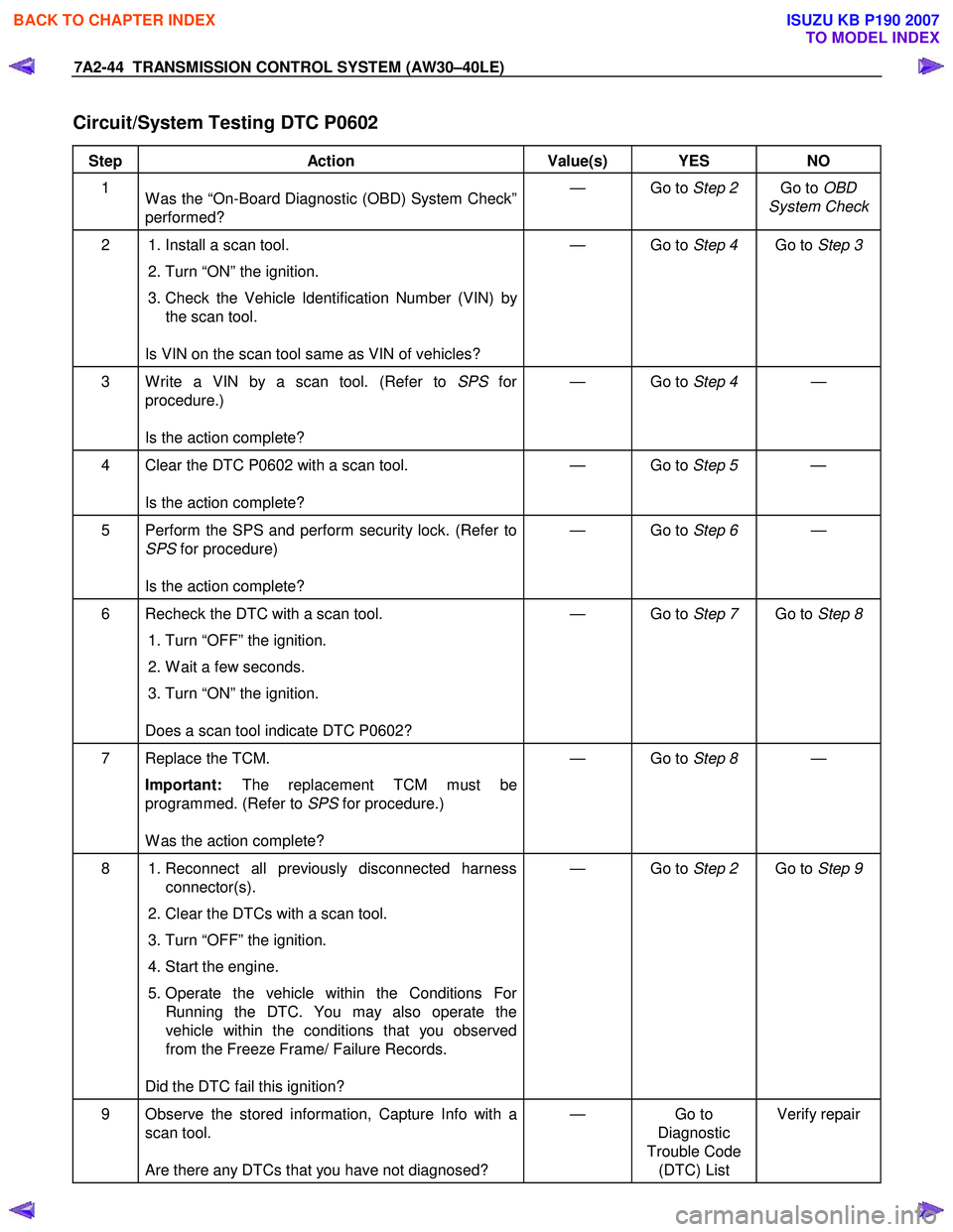
Circuit/System Testing DTC P0602
Step Action Value(s) YES NO
1
W as the “On-Board Diagnostic (OBD) System Check”
performed? — Go to
Step 2 Go to OBD
System Check
2 1. Install a scan tool.
2. Turn “ON” the ignition.
3. Check the Vehicle Identification Number (VIN) by the scan tool.
Is VIN on the scan tool same as VIN of vehicles? — Go to
Step 4 Go to Step 3
3 W rite a VIN by a scan tool. (Refer to SPS for
procedure.)
Is the action complete? — Go to
Step 4 —
4 Clear the DTC P0602 with a scan tool.
Is the action complete? — Go to
Step 5 —
5 Perform the SPS and perform security lock. (Refer to
SPS for procedure)
Is the action complete? — Go to
Step 6 —
6 Recheck the DTC with a scan tool.
1. Turn “OFF” the ignition.
2. W ait a few seconds.
3. Turn “ON” the ignition.
Does a scan tool indicate DTC P0602? — Go to
Step 7 Go to Step 8
7 Replace the TCM.
Important: The replacement TCM must be
programmed. (Refer to SPS for procedure.)
W as the action complete? — Go to
Step 8 —
8 1. Reconnect all previously disconnected harness
connector(s).
2. Clear the DTCs with a scan tool.
3. Turn “OFF” the ignition.
4. Start the engine.
5. Operate the vehicle within the Conditions For Running the DTC. You may also operate the
vehicle within the conditions that you observed
from the Freeze Frame/ Failure Records.
Did the DTC fail this ignition? — Go to
Step 2 Go to Step 9
9 Observe the stored information, Capture Info with a
scan tool.
Are there any DTCs that you have not diagnosed? — Go
to
Diagnostic
Trouble Code (DTC) List Verify repair
BACK TO CHAPTER INDEX
TO MODEL INDEX
ISUZU KB P190 2007
Page 4069 of 6020
TRANSMISSION CONTROL SYSTEM (AW30–40LE) 7A2-103
DTC P1791 (Flash Code 62)
Description
DTC P1791 is recorded by TCM when there is
malfunction in the RAM.
Condition For Running The DTC
Execute only one time after ignition “ON”.
Condition For Setting The DTC
One of the following conditions are met two times
continuously.
• W rite Ox5a5a5a5a into RAM, and read value is not
same as Ox5a5a5a5a.
• W rite Oxa5a5a5a5 into RAM, and read value is not
same as Oxa5a5a5a5.
Action Taken The DTC Sets
• Check Trans “ON”.
• DTC stored.
• MIL request “ON”. (EURO 4 only)
Conditions For Clearing The DTC
• The DTC can be cleared from the TCM history by
using a scan tool.
• The DTC will be cleared from history when the vehicle has achieved 40 warm-up cycles without a
failure reported.
•
After more than 1 second has elapsed after the
ignition key has been turned “ON”, short between
No.11 and No.4 (ground) of DLC (Data Link
Connector). Then, after 1 second, but within 6
seconds, discontinue shorting.
Diagnostic Aids
• Inspect the wiring for poor electrical connection at the
TCM. Look for possible bent, backed out, deformed
or damaged terminals. Check for weak terminal
tension as well. Also check for a chafed wire that
could short to bare metal or other wiring. Inspect for a
broken wire inside the insulation.
• W hen diagnosing for a possible intermittent short o
r
open condition, move the wiring harness while
observing test equipment for a change.
BACK TO CHAPTER INDEX
TO MODEL INDEX
ISUZU KB P190 2007