Page 4475 of 6020

ON-VEHICLE SERVICE (JR405E) 7A3-21
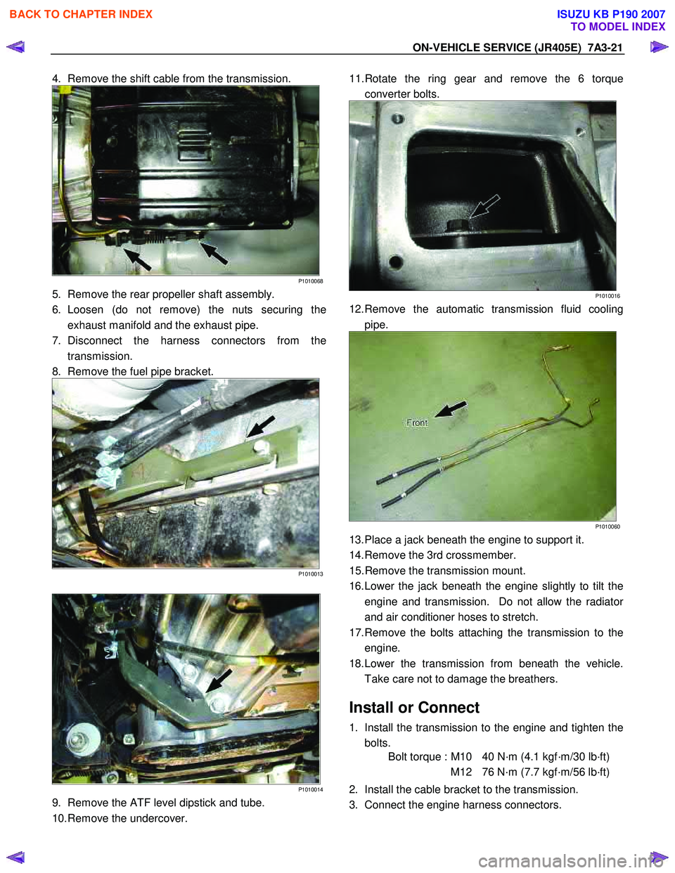
4. Remove the shift cable from the transmission.
P1010068
5. Remove the rear propeller shaft assembly.
6. Loosen (do not remove) the nuts securing the exhaust manifold and the exhaust pipe.
7. Disconnect the harness connectors from the transmission.
8. Remove the fuel pipe bracket.
P1010013
P1010014
9. Remove the ATF level dipstick and tube.
10. Remove the undercover.
11. Rotate the ring gear and remove the 6 torque
converter bolts.
P1010016
12. Remove the automatic transmission fluid cooling pipe.
P1010060
13. Place a jack beneath the engine to support it.
14. Remove the 3rd crossmember.
15. Remove the transmission mount.
16. Lower the jack beneath the engine slightly to tilt the engine and transmission. Do not allow the radiato
r
and air conditioner hoses to stretch.
17. Remove the bolts attaching the transmission to the engine.
18. Lower the transmission from beneath the vehicle. Take care not to damage the breathers.
Install or Connect
1. Install the transmission to the engine and tighten the bolts.
Bolt torque : M10 40 N·m (4.1 kgf·m/30 lb·ft)
M12 76 N·m (7.7 kgf·m/56 lb·ft)
2. Install the cable bracket to the transmission.
3. Connect the engine harness connectors.
BACK TO CHAPTER INDEX
TO MODEL INDEX
ISUZU KB P190 2007
Page 4476 of 6020

7A3-22 ON-VEHICLE SERVICE (JR405E)
4. Install the transmission mount.
Bolt torque (rubber to transmission) :
50N·m (5.1 kgf·m/37 lb·ft)
Nut torque (rubber to crossmember) :
52N·m (5.3 kgf·m/38 lb·ft)
5. Install the 3rd crossmember.
Bolt and Nut torque : 67 N·m (6.8 kgf·m/49 lb·ft)
Bolt torque : 50 N·m (5.1 kgf·m/37 lb·ft)
6. Install the automatic transmission fluid cooling pipe.
7. Install the torque converter bolts.
Bolt torque : 29 N·m (3.0 kgf·m/22 lb·ft)
8. Install the undercover.
Bolt torque : 9 N·m (0.9 kgf·m/78 lb·in)
9. Install the ATF level dipstick and tube.
10. Install the fuel hose bracket.
Bolt torque : 10 N·m (1.0 kgf·m/87 lb·in)
11. Tighten the nuts securing the exhaust manifold and the exhaust pipe.
Bolt torque : 43 N·m (4.4 kgf·m/32 lb·ft)
12. Install the rear propeller shaft assembly.
Flange bolt torque : 59 N·m (6.0 kgf·m/43 lb·ft)
Center bearing bracket bolt torque :
69 N·m (7.0 kgf·m/51 lb·ft)
13. Install the shift cable.
14. Connect the negative battery cable.
15. Remove the safety stands.
16. Remove the wheels blocks.
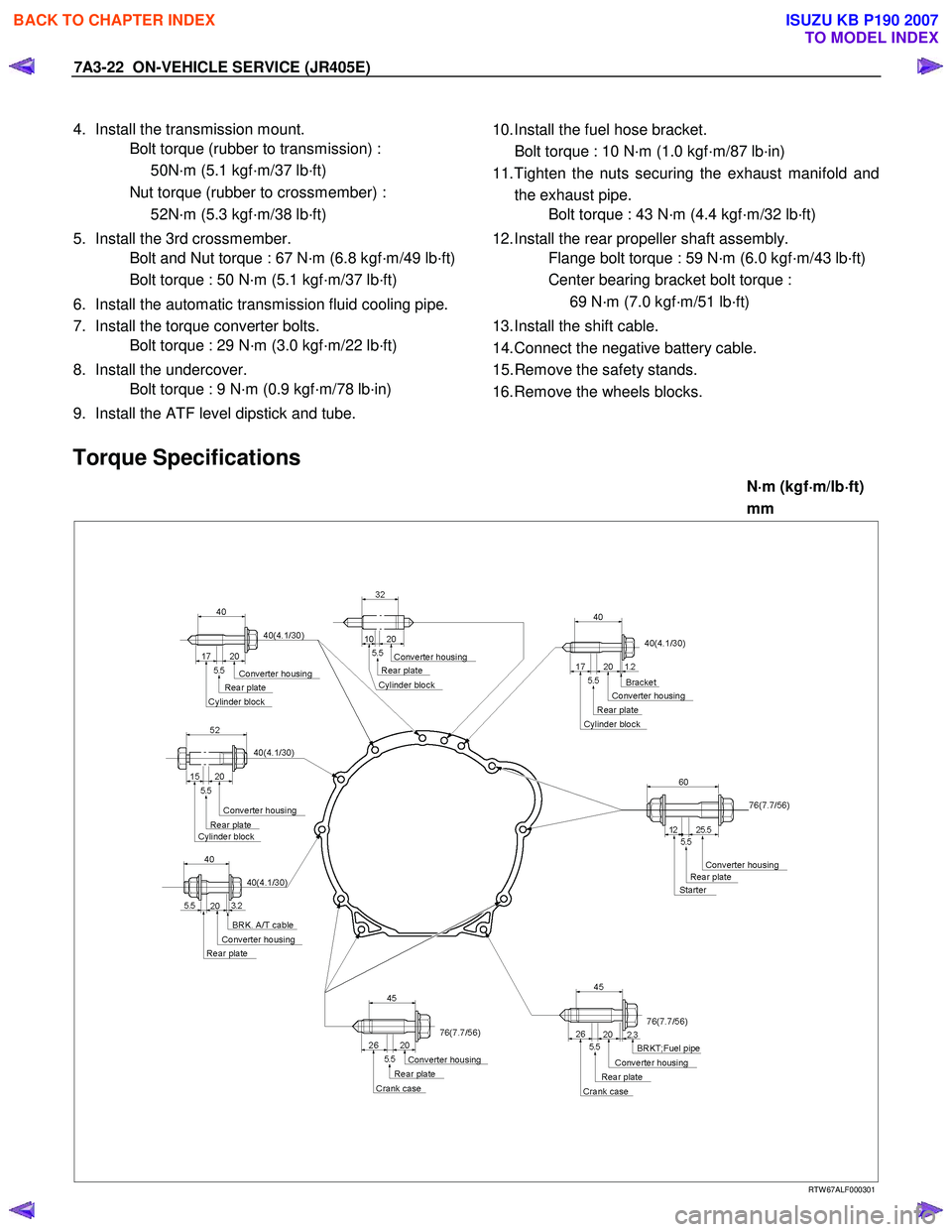
Torque Specifications
N ⋅
⋅⋅
⋅
m (kgf ⋅
⋅⋅
⋅
m/lb ⋅
⋅⋅
⋅
ft)
mm
RTW 67ALF000301
BACK TO CHAPTER INDEX
TO MODEL INDEX
ISUZU KB P190 2007
Page 4486 of 6020
UNIT REPAIR (JR405E) 7A4-9
29ASSY091
17.Output shaft
• Pull the output shaft from the transmission case.
30ASSY089
•
Remove the bearing (with bearing race) from the
transmission case.
31ASSY124
18.Parking pawl, shaft, spring, and spacer
Remove the parking pawl, shaft, spring and spacer from the
transmission case.
36ASSY075
19.Actuator support
Remove the actuator support from the transmission case.
37ASSY074
20.Low one-way clutch inner race and bearing
• Loosen the 7 bolts securing the low one-way clutch inne
r
race.
NOTE:
Loosen the bolts a little at a time as uniformly as possible
to prevent the inner race from tilting and becoming
jammed.
• Remove the 6 bolts. Support the low one-way clutch
inner race with your hand and remove the final bolt.
BACK TO CHAPTER INDEX
TO MODEL INDEX
ISUZU KB P190 2007
Page 4489 of 6020
7A4-12 UNIT REPAIR (JR405E)
06CV19
5. Solenoid
6. Oil pressure switch Remove the 6 solenoids together and the 3 oil pressure
switches.
07CV17
7. Control valve upper body
8. Control valve lower body
9. Separation plate • Remove the 17 bolts securing the control valve uppe
r
body, the control valve lower body, and the separation
plate.
08CV16
•
Separate the upper body, the lower body, and the
separation plate.
NOTE:
Take care not to drop or lose the parts at the inside of the
control valve.
Inspection
•
Inspect the separation plate for wear and other damage.
BACK TO CHAPTER INDEX
TO MODEL INDEX
ISUZU KB P190 2007
Page 4558 of 6020
UNIT REPAIR (JR405E) 7A4-81
244L300001
21.Oil pan
• Install a new gasket and the oil pan.
• Tighten the bolts to the specified torque.
Torque: 8 N ⋅
⋅⋅
⋅
m (0.8 kgf ⋅
⋅⋅
⋅
m/69 lb ⋅
⋅⋅
⋅
in)
47INH-SW 01
22.Inhibitor switch
• Secure the inhibitor switch (1) by hand-tightening the 2
bolts.
• Use the inhibitor switch set plate to align the neutral
holes (manual shaft and inhibitor switch).
Turn the inhibitor switch to adjust it.
Inhibitor switch set plate: 5-8840-2763-0
NOTE:
Inhibitor switch adjustment is very important.
If the inhibitor switch is not correctly adjusted, the
automatic transmission will not function normally.
• Tighten the 2 inhibitor switch bolts to the specified
torque.
BACK TO CHAPTER INDEX
TO MODEL INDEX
ISUZU KB P190 2007
Page 4731 of 6020

7B1-12 Manual Transmission (MUX)
22. Remove the transmission retaining nuts and bolts.Remove the transmission assembly (4x2 model) or
the transmission & transfer assembly (4x4 model)
from the vehicle.
23. Remove the transmission-transfer fixing bolts and nut, and disassemble the transfer from the
transmission. (4x4 model)
Installation
1. Apply grease (BESCO L-2 or equivalent) on the splined portion of the output shaft.
2. Connect the transfer to the transmission. (4x4 model)
3. Install the transmission-transfer fixing bolts and nut, and tighten them to the specified torque. (4x4
model)
Torque: 41 N ⋅m (4.2 kgf ⋅m/30 lb ⋅ft)
4. Apply a thin coat of molybdenum disulfide grease on the splined portion of the input shaft spline.
5. Slowly operate the transmission jack until the front of transmission is aligned with the rear of the
engine.
6. Align the input shaft spline with the clutch driven plate spline.
7. Install the transmission assembly (4x2 model) or the transmission & transfer assembly (4x4 model)
to the engine.
• Tighten the transmission bolts to the specified torque.
Torque: 76 N ⋅m (7.7 kgf ⋅m/56 lb ⋅ft)
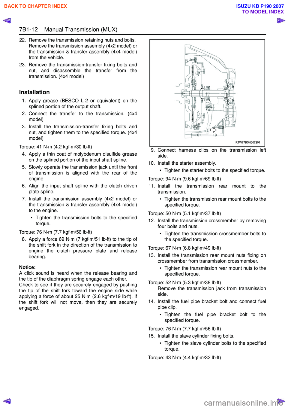
8. Apply a force 69 N ⋅m (7 kgf ⋅m/51 lb ⋅ft) to the tip of
the shift fork in the direction of the transmission to
engine the clutch pressure plate and release
bearing.
Notice:
A click sound is heard when the release bearing and
the tip of the diaphragm spring engage each other.
Check to see if they are securely engaged by pushing
the tip of the shift fork toward the engine side while
applying a force of about 25 N ⋅m (2.6 kgf ⋅m/19 lb ⋅ft). If
the shift fork will not move, then they are securely
engaged. 9. Connect harness clips on the transmission left
side.
10. Install the starter assembly.
• Tighten the starter bolts to the specified torque.
Torque: 94 N ⋅m (9.6 kgf ⋅m/69 lb ⋅ft)
11. Install the transmission rear mount to the transmission.
• Tighten the transmission rear mount bolts to the specified torque.
Torque: 50 N ⋅m (5.1 kgf ⋅m/37 lb ⋅ft)
12. Install the transmission crossmember by removing four bolts and nuts.
• Tighten the transmission crossmember bolts to the specified torque.
Torque: 67 N ⋅m (6.8 kgf ⋅m/49 lb ⋅ft)
13. Install the transmission rear mount nuts fixing on crossmember from transmission crossmember.
• Tighten the transmission rear mount nuts to the specified torque.
Torque: 52 N ⋅m (5.3 kgf ⋅m/38 lb ⋅ft)
Remove the transmission jack from transmission
side.
14. Install the fuel pipe bracket bolt and connect fuel pipe clip.
• Tighten the fuel pipe bracket bolt to the specified torque.
Torque: 76 N ⋅m (7.7 kgf ⋅m/56 lb ⋅ft)
15. Install the slave cylinder fixing bolts. • Tighten the slave cylinder bolts to the specifiedtorque.
Torque: 43 N ⋅m (4.4 kgf ⋅m/32 lb ⋅ft)
RTW77BSH007201
BACK TO CHAPTER INDEX
TO MODEL INDEX
ISUZU KB P190 2007
Page 4837 of 6020
TRANSFER CASE 7D-7
Installation
1. Thoroughly clean around the oil seal bore in the case
and ensure there are no burrs.
2.
Apply the engine oil to the new oil seal outer surfaces
and apply the recommended grease (BESCO L2) o
r
equivalent to the oil seal lip.
3. Tap the oil seal in to place, use an oil seal installe
r
(5-8840-2785-0) and a soft hammer.
RTW 77DSH000301
4. Install the output flange to the front output shaft.
5. Apply the engine oil to the new O-ring and install it to the front output shaft.
6. Secure the output flange with a flange holde
r
(5-8840-0133-0).
7. Install the new end nut and tighten them to specified torque.
Front coupling driver fixing nut torque: 137 N ⋅
⋅⋅
⋅
m (14.0 kgf ⋅
⋅⋅
⋅
m/101 lb ⋅
⋅⋅
⋅
ft)
8. Use a punch (5-8840-2293-0) to caulk the end nut.
226R300012
RUW 34DSH000301
Legend
(1) MAX 26mm (1.02in)
(2) MIN 4mm (0.16in)
BACK TO CHAPTER INDEX
TO MODEL INDEX
ISUZU KB P190 2007
Page 4856 of 6020
7D-26 TRANSFER CASE
2-4 shift reassembly
1. Install the shift block assembly to the shift rod.
2. Install the spring pin. The head of the pin must not
project beyond the surface (1) of the shift block.
226R300015
3. Install the spring.
4. Install the shift arm.
5. Compress the spring and install the snap ring.
6. Install the guide roller.
Oil pump disassembly
1. Remove the clamps securing the screen.
2. Remove the screen.
3. Remove the clamps securing the hose.
4. Remove the hose.
NOTE: To maintain and protect oil pump function, the
pump is constructed so that it cannot be disassembled.
Under no conditions attempt to disassemble the pump.
Oil pump reassembly
1. Tighten the clamps to secure the hose.
2. Tighten the clamps to secure the screen.
NOTE: Be careful in the direction of clamps.
RTW 37DSH000101
Legend
(1) Oil Pump Assembly
(2) Clamp
(3) Hose
(4) Screen Assembly
BACK TO CHAPTER INDEX
TO MODEL INDEX
ISUZU KB P190 2007