2007 ISUZU KB P190 ECU
[x] Cancel search: ECUPage 3906 of 6020
Automatic Transmission – 4L60E – Electrical Diagnosis Page 7C2–120
Action Taken When the DTC Sets
• The TCM requests the ECM to illuminate the MIL during the second consecutive trip in which the conditions for
setting the DTC are met.
• The TCM commands maximum line pressure.
• The TCM freezes transmission adaptive functions.
• The TCM inhibits TCC engagement.
• The TCM inhibits 4th gear if in hot mode.
• At the time of the first failure, the TCM records the operating conditions when the conditions for setting the DTC are
met. The TCM stores this information as a Failure Record.
• At the time of the second failure, the ECM records the operating conditions when the conditions for setting the DTC
are met. The ECM stores this information as a Freeze Frame.
• The TCM stores DTC P2770 in TCM history during the second consecutive trip in which the conditions for setting
the DTC are met.
Conditions for Clearing the DTC
• The ECM turns off the MIL after the fourth consecutive drive trip in which the TCM does not send a MIL illumination
request.
• Tech 2 can clear the DTC.
• The TCM clears the DTC from TCM history if the vehicle completes 40 warm-up cycles without a non-emission
related diagnostic fault occurring.
• The TCM cancels the DTC default actions when the ignition is off long enough to power down the TCM.
Test Description
The following numbers refer to the step numbers in the diagnostic table:
2 Checks for a short to voltage in the TCC solenoid valve signal circuit. Isolates whether the TCM or the TCC solenoid valve and control valve body wiring harness are at fault.
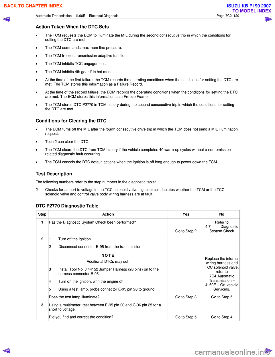
DTC P2770 Diagnostic Table
Step Action Yes No
1 Has the Diagnostic System Check been performed?
Go to Step 2 Refer to
4.7 Diagnostic System Check
2 1 Turn off the ignition.
2 Disconnect connector E-95 from the transmission.
NOTE
Additional DTCs may set.
3 Install Tool No. J 44152 Jumper Harness (20 pins) on to the harness connector E-95.
4 Turn on the ignition, with the engine off.
5 Using a test lamp, probe connector E-95 pin 20 to ground.
Does the test lamp illuminate? Go to Step 3 Replace the internal
wiring harness and
TCC solenoid valve, refer to
7C4 Automatic
Transmission –
4L60E – On-vehicle
Servicing.
Go to Step 5
3 Using a multimeter, test between E-95 pin 20 and C-96 pin 25 for a
short to voltage.
Did you find and correct the condition? Go to Step 5 Go to Step 4
BACK TO CHAPTER INDEX
TO MODEL INDEX
ISUZU KB P190 2007
Page 3908 of 6020
Automatic Transmission – 4L60E – Electrical Diagnosis Page 7C2–122
Action Taken When the DTC Sets
• The TCM requests the ECM to illuminate the MIL during the second consecutive trip in which the conditions for
setting the DTC are met.
• The TCM commands maximum line pressure.
• The TCM freezes transmission adaptive functions.
• The TCM inhibits TCC engagement.
• At the time of the first failure, the TCM records the operating conditions when the conditions for setting the DTC are
met. The TCM stores this information as a Failure Record.
• At the time of the second failure, the ECM records the operating conditions when the conditions for setting the DTC
are met. The ECM stores this information as a Freeze Frame.
• The TCM stores either DTC U0073 or DTC U0100 in TCM history during the second consecutive trip in which the
conditions for setting the DTC are met.
Conditions for Clearing the DTC
• The ECM turns off the MIL after the fourth consecutive drive trip in which the TCM does not send a MIL illumination
request.
• Tech 2 can clear the DTC.
• The TCM clears the DTC from TCM history if the vehicle completes 40 warm-up cycles without a non-emission
related diagnostic fault occurring.
• The TCM cancels the DTC default actions when the ignition is off long enough to power down the TCM.
Test Description
The following number refers to the step numbers in the diagnostic table:
1 The following tests are included in the Diagnostic System Check.
• Tests the integrity of the GM LAN serial data communication circuit.
• Tests for fault conditions on the vehicle immobiliser system stored in the ICU.
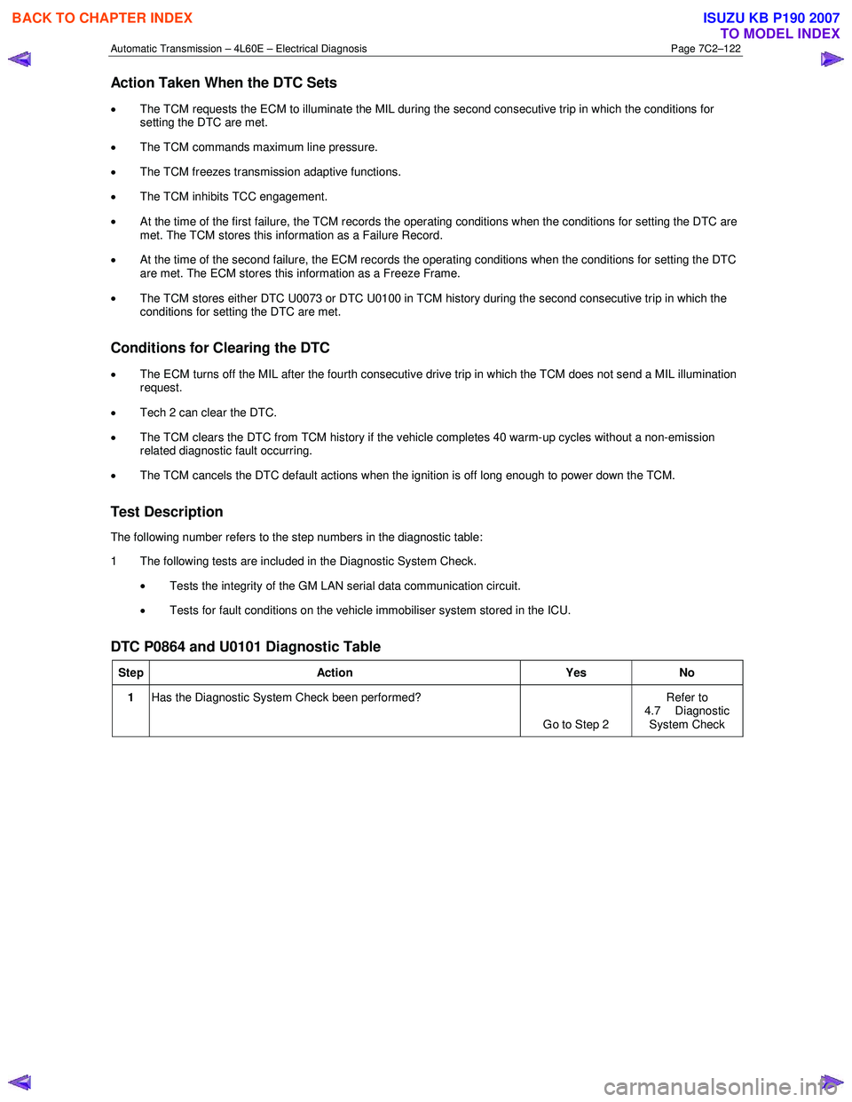
DTC P0864 and U0101 Diagnostic Table
Step Action Yes No
1 Has the Diagnostic System Check been performed?
Go to Step 2 Refer to
4.7 Diagnostic System Check
BACK TO CHAPTER INDEX
TO MODEL INDEX
ISUZU KB P190 2007
Page 3925 of 6020
Automatic Transmission – 4L60E – On-vehicle Servicing Page 7C4–12
4 Remove the knob together with the button (5) and spring (6) from the selector lever assembly (7).
5 Turn the sleeve (8) counter clockwise to remove it, make note of the number of turns required to free it.
6 Remove the harness connectors from the base plate (9).
7 Remove the upper housing (10) which is held in place by four latched fasteners.
8 Remove the attaching screw (11) and spring plate (12).
9 Remove the grooved pin (13).
10 Using a small flat blade screwdriver, gently prise the upper end of the selector cable (14) from the pin on the selector lever linkage (15).
11 Remove the selector lever assembly by pressing the rod down (lever in the N position).
12 If required, remove the lamp (16) from its socket by aligning the groove in the socket and the protruding part of the lamp.
13 If required, remove the nut (17), four places, and the shift selector base plate.
Reinstall
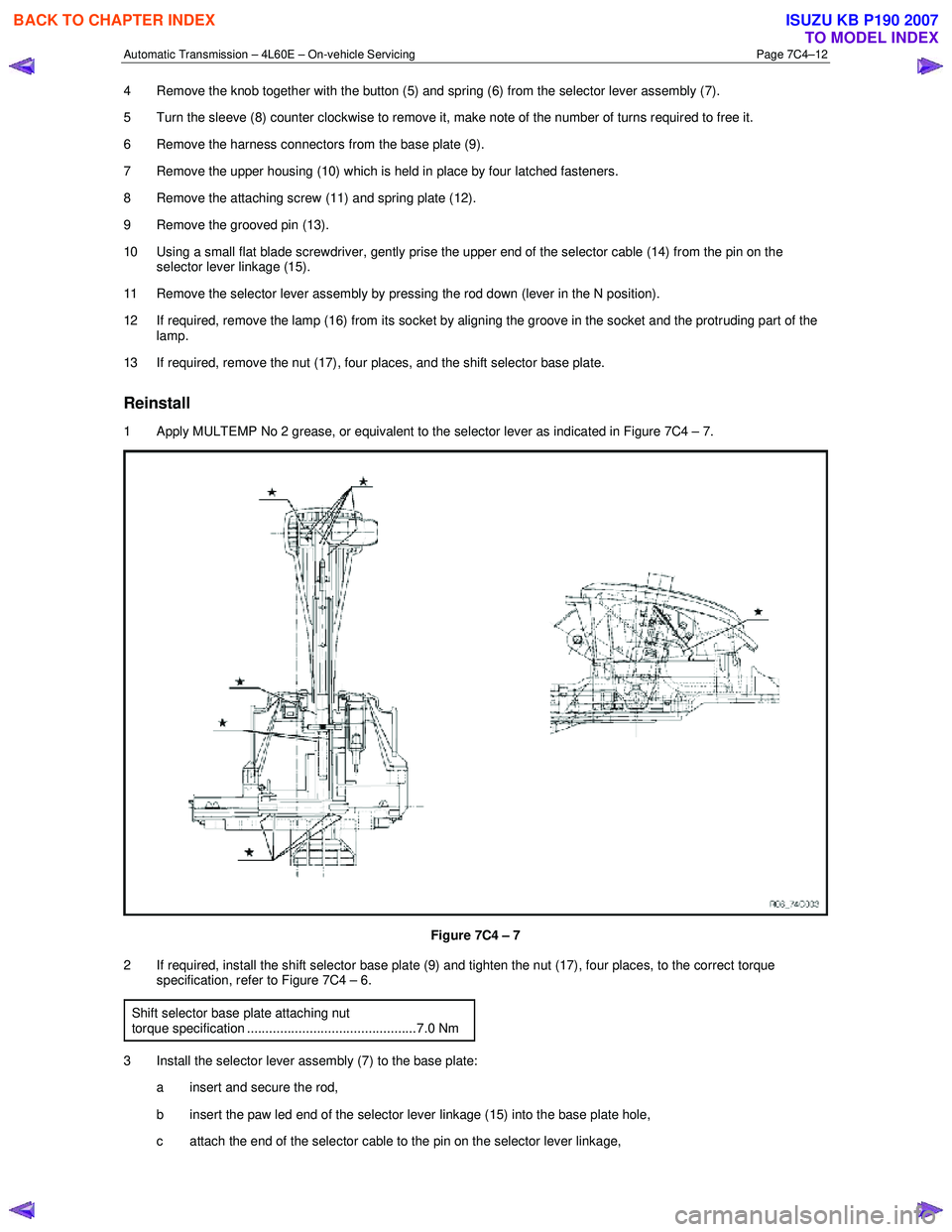
1 Apply MULTEMP No 2 grease, or equivalent to the selector lever as indicated in Figure 7C4 – 7.
Figure 7C4 – 7
2 If required, install the shift selector base plate (9) and tighten the nut (17), four places, to the correct torque specification, refer to Figure 7C4 – 6.
Shift selector base plate attaching nut
torque specification ..............................................7.0 Nm
3 Install the selector lever assembly (7) to the base plate: a insert and secure the rod,
b insert the paw led end of the selector lever linkage (15) into the base plate hole,
c attach the end of the selector cable to the pin on the selector lever linkage,
BACK TO CHAPTER INDEX
TO MODEL INDEX
ISUZU KB P190 2007
Page 3926 of 6020
Automatic Transmission – 4L60E – On-vehicle Servicing Page 7C4–13
d Install the grooved pin (13) in the selector lever.
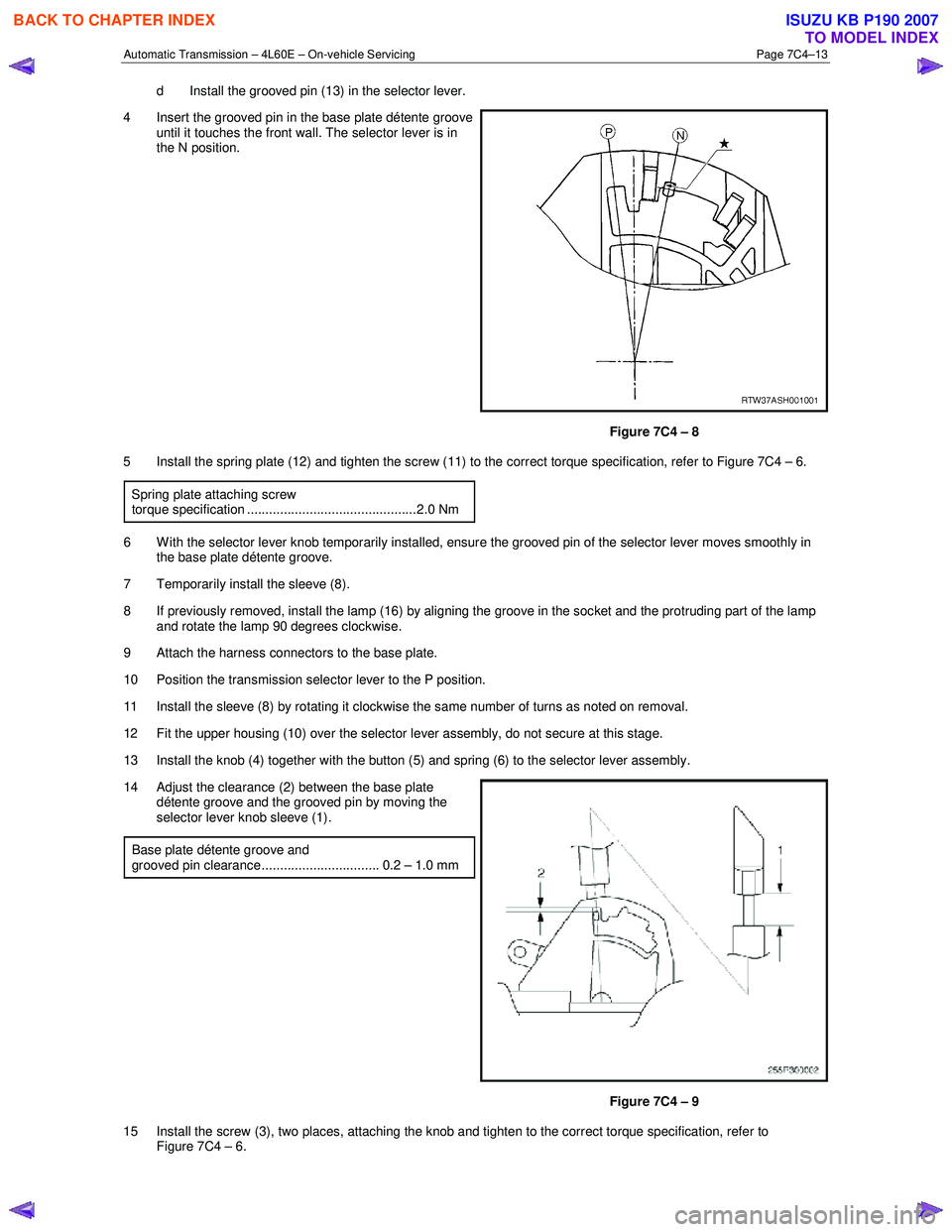
4 Insert the grooved pin in the base plate détente groove until it touches the front wall. The selector lever is in
the N position.
Figure 7C4 – 8
5 Install the spring plate (12) and tighten the screw (11) to the correct torque specification, refer to Figure 7C4 – 6.
Spring plate attaching screw
torque specification ..............................................2.0 Nm
6 W ith the selector lever knob temporarily installed, ensure the grooved pin of the selector lever moves smoothly in the base plate détente groove.
7 Temporarily install the sleeve (8).
8 If previously removed, install the lamp (16) by aligning the groove in the socket and the protruding part of the lamp and rotate the lamp 90 degrees clockwise.
9 Attach the harness connectors to the base plate.
10 Position the transmission selector lever to the P position.
11 Install the sleeve (8) by rotating it clockwise the same number of turns as noted on removal.
12 Fit the upper housing (10) over the selector lever assembly, do not secure at this stage.
13 Install the knob (4) together with the button (5) and spring (6) to the selector lever assembly.
14 Adjust the clearance (2) between the base plate détente groove and the grooved pin by moving the
selector lever knob sleeve (1).
Base plate détente groove and
grooved pin clearance................................ 0.2 – 1.0 mm
Figure 7C4 – 9
15 Install the screw (3), two places, attaching the knob and tighten to the correct torque specification, refer to Figure 7C4 – 6.
BACK TO CHAPTER INDEX
TO MODEL INDEX
ISUZU KB P190 2007
Page 3927 of 6020
Automatic Transmission – 4L60E – On-vehicle Servicing Page 7C4–14
Selector lever knob attaching screw torque specification ..............................................2.0 Nm
16 Secure the upper housing (10) to the base plate with the four latched fasteners.
17 Install the front and rear console, refer to 10 Cab.
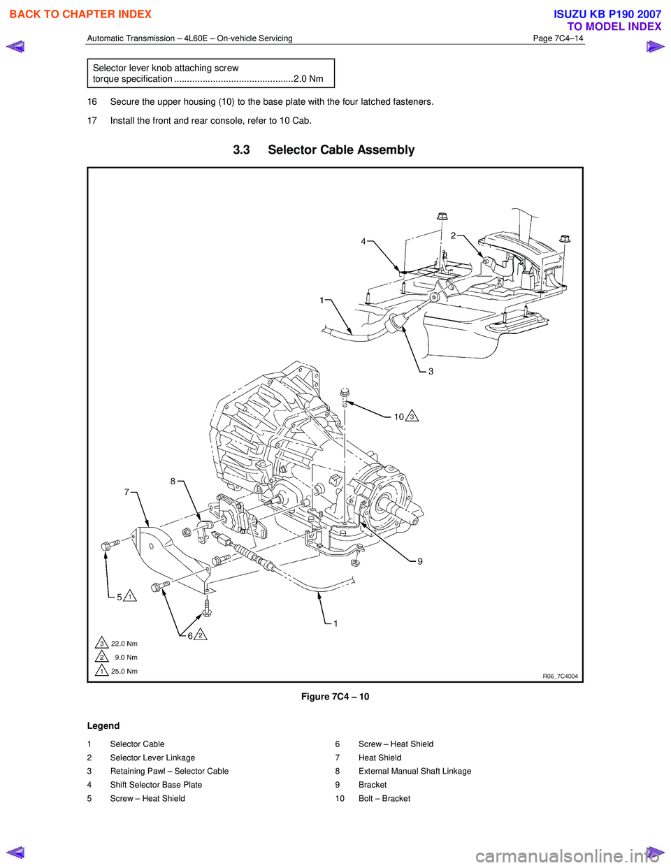
3.3 Selector Cable Assembly
Figure 7C4 – 10
Legend
1 Selector Cable
2 Selector Lever Linkage
3 Retaining Pawl – Selector Cable
4 Shift Selector Base Plate
5 Screw – Heat Shield 6 Screw – Heat Shield
7 Heat Shield
8 External Manual Shaft Linkage
9 Bracket
10 Bolt – Bracket
BACK TO CHAPTER INDEX
TO MODEL INDEX
ISUZU KB P190 2007
Page 3929 of 6020
Automatic Transmission – 4L60E – On-vehicle Servicing Page 7C4–16
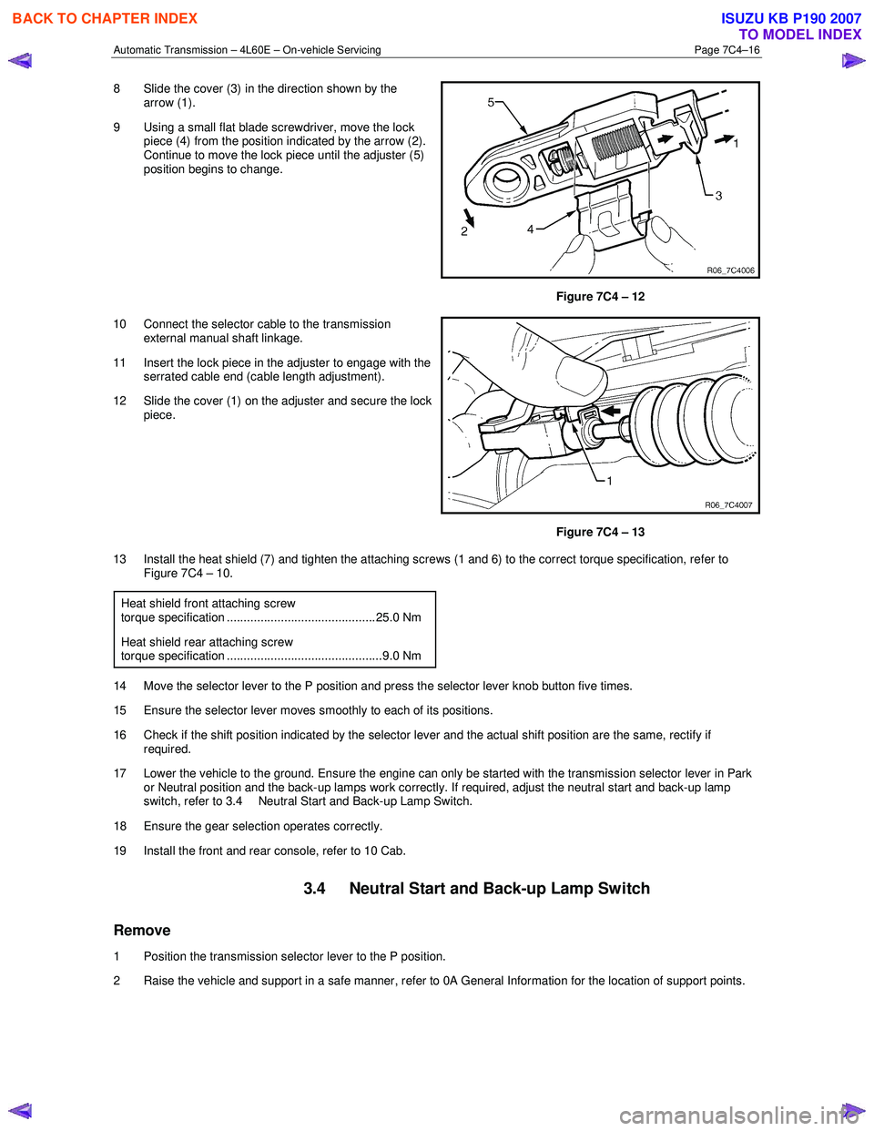
8 Slide the cover (3) in the direction shown by the
arrow (1).
9 Using a small flat blade screwdriver, move the lock piece (4) from the position indicated by the arrow (2).
Continue to move the lock piece until the adjuster (5)
position begins to change.
Figure 7C4 – 12
10 Connect the selector cable to the transmission external manual shaft linkage.
11 Insert the lock piece in the adjuster to engage with the serrated cable end (cable length adjustment).
12 Slide the cover (1) on the adjuster and secure the lock piece.
Figure 7C4 – 13
13 Install the heat shield (7) and tighten the attaching screws (1 and 6) to the correct torque specification, refer to Figure 7C4 – 10.
Heat shield front attaching screw
torque specification ............................................ 25.0 Nm
Heat shield rear attaching screw torque specification ..............................................9.0 Nm
14 Move the selector lever to the P position and press the selector lever knob button five times.
15 Ensure the selector lever moves smoothly to each of its positions.
16 Check if the shift position indicated by the selector lever and the actual shift position are the same, rectify if required.
17 Lower the vehicle to the ground. Ensure the engine can only be started with the transmission selector lever in Park or Neutral position and the back-up lamps work correctly. If required, adjust the neutral start and back-up lamp
switch, refer to 3.4 Neutral Start and Back-up Lamp Switch.
18 Ensure the gear selection operates correctly.
19 Install the front and rear console, refer to 10 Cab.
3.4 Neutral Start and Back-up Lamp Switch
Remove
1 Position the transmission selector lever to the P position.
2 Raise the vehicle and support in a safe manner, refer to 0A General Information for the location of support points.
BACK TO CHAPTER INDEX
TO MODEL INDEX
ISUZU KB P190 2007
Page 3930 of 6020

Automatic Transmission – 4L60E – On-vehicle Servicing Page 7C4–17
3 Remove the three attaching screws (1 and 2) and the
heat shield (3).
4 Hold the transmission manual shaft linkage (4) with an adjustable wrench and remove the linkage attaching
nut (5).
5 Carefully remove the manual shaft linkage and selector cable from the transmission manual shaft (6).
6 Prise the connector position assurance (CPA) securing pin (7) from the neutral start and back-up
lamp switch (8) taking care not to break the pin in the
process. Disconnect the connector (9) from the switch
assembly by pulling down the release bar (10).
NOTE
The connector will automatically disconnect at
the same time the release bar is withdrawn.
7 Remove the attaching screw (11) and slide the switch assembly over the transmission manual shaft to
remove it.
Figure 7C4 – 14
Reinstall
1 Slide the neutral start and back-up lamp switch (8) over the transmission manual shaft (6) and reinstall the two
attaching screws (1 and 11), tighten them finger tight until the adjustment process has been completed, refer to
Figure 7C4 – 14.
2 Install the manual shaft linkage (4) and the attaching nut (5). Hold the linkage with an adjustable wrench and tighten the nut to the correct torque specification.
Manual shaft linkage attaching nut
torque specification ............................................ 25.0 Nm
3 Install the connector (9) but do not reinsert the CPA securing pin (7) at this stage.
4 Check the shift selector linkage operation and adjust as required, refer to 3.2 Shift Selector Assembly.
5 Check and adjust as required the neutral start and back-up lamp switch as described in this Section, refer to Adjust.
Adjust
1 Raise the vehicle and support in a safe manner, refer to 0A General Information for the location of support points.
2 If required, loosen the neutral start and back-up lamp switch (8) as follows, refer to Figure 7C4 – 14: a Remove the three attaching screws (1 and 2) and the heat shield (3).
b Prise the connector position assurance (CPA) securing pin (7) from the neutral start and back-up lamp switch taking care not to break the pin in the process.
c Disconnect connector (9) from the switch assembly by pulling down the release bar (10).
NOTE
The connector will automatically disconnect at the
same time the release bar is withdrawn.
d Loosen the screw (11) attaching the switch and refit the front screw (1) keep them finger tight.
e Reinstall the connector (9) but do not reinsert the CPA securing pin at this stage.
3 Rotate the neutral start and back-up lamp switch back and forth until a central position is attained and then lightly tighten the front screw (1) to prevent the switch from rotating.
BACK TO CHAPTER INDEX
TO MODEL INDEX
ISUZU KB P190 2007
Page 3931 of 6020
Automatic Transmission – 4L60E – On-vehicle Servicing Page 7C4–18
Ensure the four wheels are off the ground
before performing the starting test.
4 W ith the ignition switched to the ON position, check if the engine can only be started in the Park and Neutral shift selector positions and ensure the back-up lamps illuminate when Reverse is selected. A further minor adjustment
may be required to achieve this state.
NOTE
To gain access to the rear attaching screw (11) it
will be necessary to remove the connector.
5 After the switch has been adjusted, tighten the rear attaching screw (11) to the correct torque specification. Neutral start and back-up lamp switch
attaching screw torque specification .................. 25.0 Nm
6 Reinstall the connector and the CPA securing pin.
7 Remove the switch front attaching screw (1).
8 Install the heat shield (3) and tighten the attaching screws (1 and 2) to the correct torque specification.
Heat shield front attaching screw
torque specification ............................................ 25.0 Nm
Heat shield rear attaching screw torque specification ..............................................9.0 Nm
9 Lower the vehicle to the ground and re-check the operation of the neutral start and back-up lamp switch. The vehicle must start only with the shift selector in the Park or Neutral positions and the back-up lamps should only
illuminate when Reverse is selected.
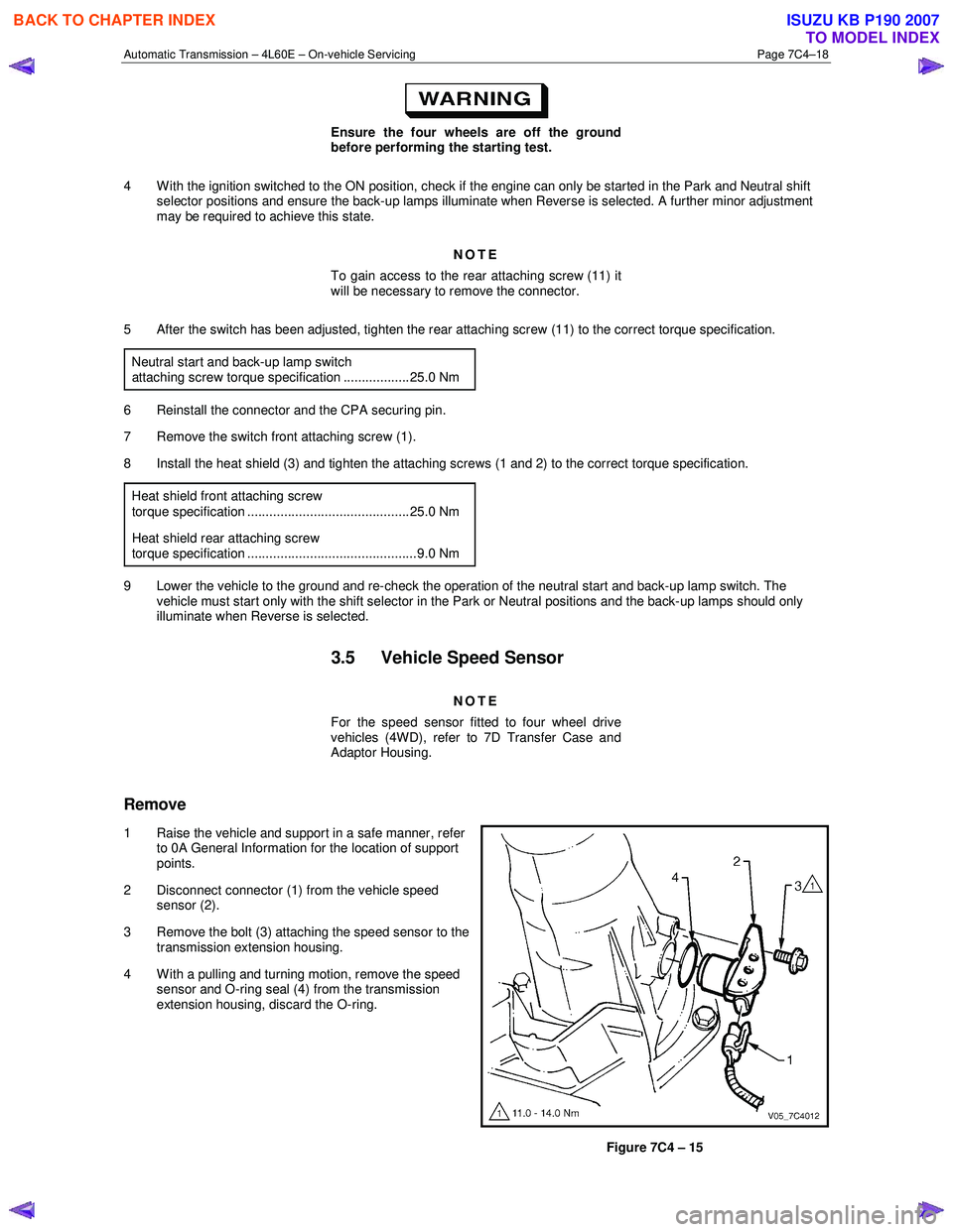
3.5 Vehicle Speed Sensor
NOTE
For the speed sensor fitted to four wheel drive
vehicles (4WD), refer to 7D Transfer Case and
Adaptor Housing.
Remove
1 Raise the vehicle and support in a safe manner, refer
to 0A General Information for the location of support
points.
2 Disconnect connector (1) from the vehicle speed sensor (2).
3 Remove the bolt (3) attaching the speed sensor to the transmission extension housing.
4 With a pulling and turning motion, remove the speed sensor and O-ring seal (4) from the transmission
extension housing, discard the O-ring.
Figure 7C4 – 15
BACK TO CHAPTER INDEX
TO MODEL INDEX
ISUZU KB P190 2007