2007 ISUZU KB P190 ECU
[x] Cancel search: ECUPage 3740 of 6020
Powertrain Interface Module – V6 Page 6E1–79
13 Powertrain Interface Module –
Tech 2 Functions
13.1 Introduction
Do not use a Tech 2 that displays faulty data;
have the Tech 2 repaired. The use of a faulty
Tech 2 can result in misdiagnosis and the
unnecessary replacement of parts.
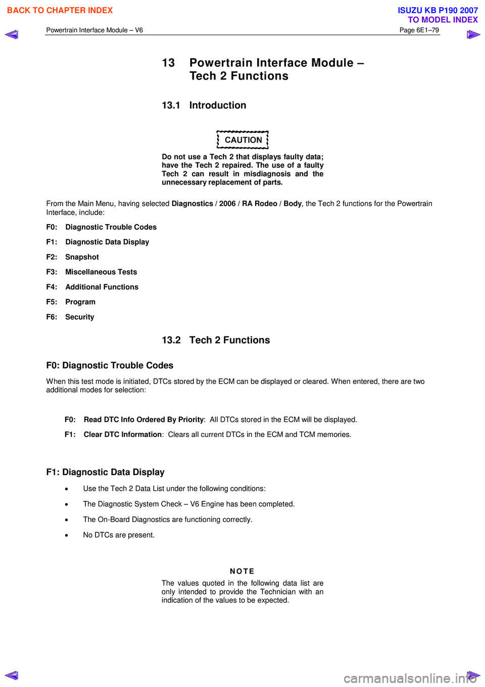
From the Main Menu, having selected Diagnostics / 2006 / RA Rodeo / Body , the Tech 2 functions for the Powertrain
Interface, include:
F0: Diagnostic Trouble Codes
F1: Diagnostic Data Display
F2: Snapshot
F3: Miscellaneous Tests
F4: Additional Functions
F5: Program
F6: Security
13.2 Tech 2 Functions
F0: Diagnostic Trouble Codes
W hen this test mode is initiated, DTCs stored by the ECM can be displayed or cleared. W hen entered, there are two
additional modes for selection:
F0: Read DTC Info Ordered By Priority : All DTCs stored in the ECM will be displayed.
F1: Clear DTC Information : Clears all current DTCs in the ECM and TCM memories.
F1: Diagnostic Data Display
• Use the Tech 2 Data List under the following conditions:
• The Diagnostic System Check – V6 Engine has been completed.
• The On-Board Diagnostics are functioning correctly.
• No DTCs are present.
NOTE
The values quoted in the following data list are
only intended to provide the Technician with an
indication of the values to be expected.
BACK TO CHAPTER INDEX
TO MODEL INDEX
ISUZU KB P190 2007
Page 3741 of 6020
Powertrain Interface Module – V6 Page 6E1–80
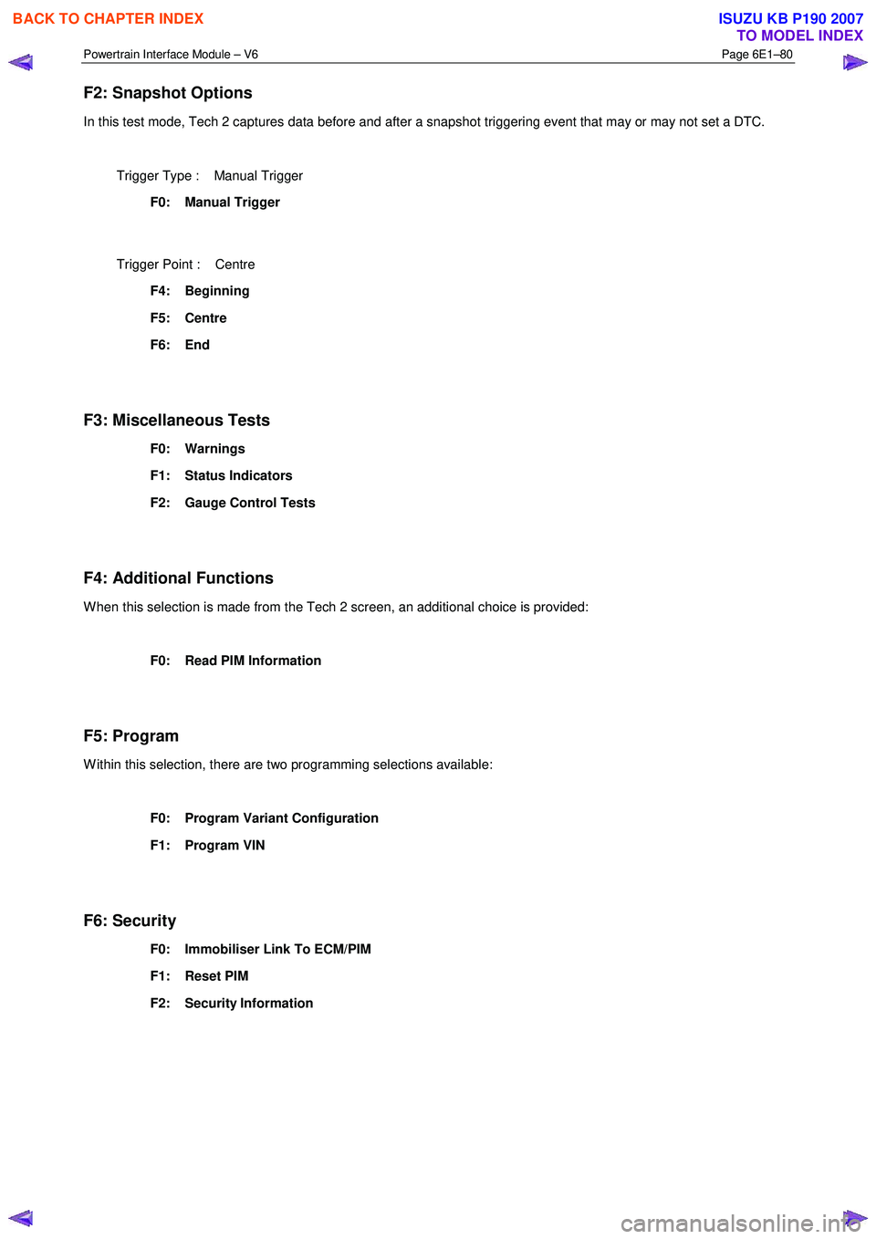
F2: Snapshot Options
In this test mode, Tech 2 captures data before and after a snapshot triggering event that may or may not set a DTC.
Trigger Type : Manual Trigger
F0: Manual Trigger
Trigger Point : Centre
F4: Beginning
F5: Centre
F6: End
F3: Miscellaneous Tests
F0: Warnings
F1: Status Indicators
F2: Gauge Control Tests
F4: Additional Functions
W hen this selection is made from the Tech 2 screen, an additional choice is provided:
F0: Read PIM Information
F5: Program
W ithin this selection, there are two programming selections available:
F0: Program Variant Configuration
F1: Program VIN
F6: Security
F0: Immobiliser Link To ECM/PIM
F1: Reset PIM
F2: Security Information
BACK TO CHAPTER INDEX
TO MODEL INDEX
ISUZU KB P190 2007
Page 3744 of 6020
Powertrain Interface Module – V6 Page 6E1–83
13.5 Security
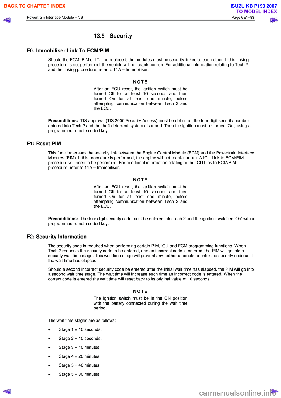
F0: Immobiliser Link To ECM/PIM
Should the ECM, PIM or ICU be replaced, the modules must be security linked to each other. If this linking
procedure is not performed, the vehicle will not crank nor run. For additional information relating to Tech 2
and the linking procedure, refer to 11A – Immobiliser.
NOTE
After an ECU reset, the ignition switch must be
turned Off for at least 10 seconds and then
turned On for at least one minute, before
attempting communication between Tech 2 and
the ECU.
Preconditions: TIS approval (TIS 2000 Security Access) must be obtained, the four digit security number
entered into Tech 2 and the theft deterrent system disarmed. Then the ignition must be turned ‘On’, using a
programmed remote coded key.
F1: Reset PIM
This function erases the security link between the Engine Control Module (ECM) and the Powertrain Interface Modules (PIM). If this procedure is performed, the engine will not crank nor run. A ICU Link to ECM/PIM
procedure will need to be performed. For additional information relating to the ICU Link to ECM/PIM
procedure, refer to 11A – Immobiliser.
NOTE
After an ECU reset, the ignition switch must be
turned Off for at least 10 seconds and then
turned On for at least one minute, before
attempting communication between Tech 2 and
the ECU.
Preconditions: The four digit security code must be entered into Tech 2 and the ignition switched ‘On’ with a
programmed remote coded key.
F2: Security Information
The security code is required when performing certain PIM, ICU and ECM programming functions. W hen Tech 2 requests the security code to be entered, and an incorrect code is entered, the PIM will go into a
security wait time stage. This wait time stage will prevent any further attempts to enter the security code until
the wait time has elapsed.
Should a second incorrect security code be entered after the initial wait time has elapsed, the PIM will go into a second wait time stage. The wait time will increase each time an incorrect code is entered. W hen the
correct code is entered the wait time will reset back to its original value of 10 seconds.
NOTE
The ignition switch must be in the ON position
with the battery connected during the wait time
period.
The wait time stages are as follows: • Stage 1 = 10 seconds.
• Stage 2 = 10 seconds.
• Stage 3 = 10 minutes.
• Stage 4 = 20 minutes.
• Stage 5 = 40 minutes.
• Stage 5 = 80 minutes.
BACK TO CHAPTER INDEX
TO MODEL INDEX
ISUZU KB P190 2007
Page 3745 of 6020
Powertrain Interface Module – V6 Page 6E1–84
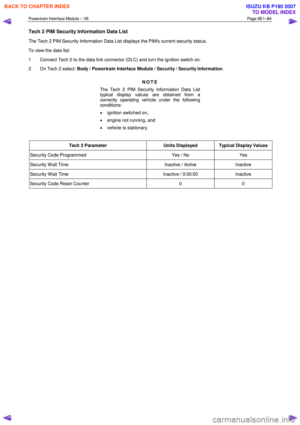
Tech 2 PIM Security Information Data List
The Tech 2 PIM Security Information Data List displays the PIM's current security status.
To view the data list:
1 Connect Tech 2 to the data link connector (DLC) and turn the ignition switch on.
2 On Tech 2 select: Body / Powertrain Interface Module / Security / Security Information .
NOTE
The Tech 2 PIM Security Information Data List
typical display values are obtained from a
correctly operating vehicle under the following
conditions:
• ignition switched on,
• engine not running, and
• vehicle is stationary.
Tech 2 Parameter Units Displayed Typical Display Values
Security Code Programmed Yes / No Yes
Security W ait Time Inactive / Active Inactive
Security W ait Time Inactive / 0:00:00 Inactive
Security Code Reset Counter 0 0
BACK TO CHAPTER INDEX
TO MODEL INDEX
ISUZU KB P190 2007
Page 3775 of 6020

Automatic Transmission – 4L60E – General Information Page 7C1–15
5 Service Notes
In the interests of safety to personnel, equipment and to the vehicle and its components, read and adhere to the following
notes whenever servicing operations are to be carried out on the Hydra-matic 4L60E automatic transmission. In addition,
some of this information also refers to sound workshop practices and, to achieve the design life of affected components.
Fasteners
• Always reinstall fasteners in the same locations as they were removed.
• If a fastener requires replacement, always use a part of the correct part number or of equal size and strength or
stronger.
General Workshop Practice
• Keep work area and tools clean.
• To avoid unnecessary contamination, always clean the exterior of the transmission before removing any parts.
• Do not use wiping cloths or rags because of the risk of lint being trapped in the transmission.
• Do not use solvents on:
• neoprene seals,
• composition faced clutch plates, or
• thrust washers.
• Always wear eye protection when using compressed air.
• Blow out all passages with compressed air. Only probe small passages with soft, thin wire.
• Handle parts with care to avoid nicks and scratches.
• Do not remove Teflon oil seal rings unless damaged or performing a complete overhaul.
• Expand internal snap rings and compress external snap rings to maximise retention and security.
• Lubricate all internal parts with transmission fluid (only use Dexron® III), as they are being installed.
• When installing cap screws into aluminium castings:
• always use a torque wrench and
• stripped or damaged threads in aluminium castings may be reconditioned by using commercially available
thread inserts.
• Once removed, replace all gaskets, seals and O-rings with new parts.
• Always use seal protectors where indicated and do not use gasket cement or sealant on any joined face unless
specified to do so.
BACK TO CHAPTER INDEX
TO MODEL INDEX
ISUZU KB P190 2007
Page 3781 of 6020
Automatic Transmission – 4L60E – General Information Page 7C1–21
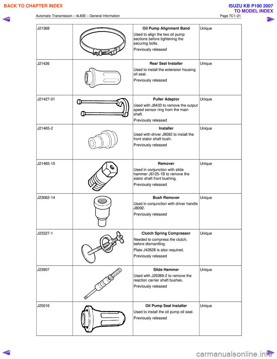
J21368
Oil Pump Alignment Band
Used to align the two oil pump
sections before tightening the
securing bolts.
Previously released Unique
J21426
Rear Seal Installer
Used to install the extension housing
oil seal.
Previously released Unique
J21427-01 Puller Adaptor
Used with J8433 to remove the output
speed sensor ring from the main
shaft.
Previously released Unique
J21465-2
Installer
Used with driver J8092 to install the
front stator shaft bush.
Previously released Unique
J21465-15
Remover
Used in conjunction with slide
hammer J6125-1B to remove the
stator shaft front bushing.
Previously released Unique
J23062-14
Bush Remover
Used in conjunction with driver handle
J8092.
Previously released Unique
J23327-1
Clutch Spring Compressor
Needed to compress the clutch,
before dismantling.
Plate J42628 is also required.
Previously released Unique
J23907
Slide Hammer
Used with J29369-2 to remove the
reaction carrier shaft bushes.
Previously released Unique
J25016
Oil Pump Seal Installer
Used to install the oil pump oil seal.
Previously released Unique
BACK TO CHAPTER INDEX
TO MODEL INDEX
ISUZU KB P190 2007
Page 3796 of 6020
Automatic Transmission – 4L60E – Electrical Diagnosis Page 7C2–10
Limp Home Mode Description
If a major electrical system failure occurs which could affect vehicle safety or damage the transmission during normal
operation, the TCM enters a limp home mode. In the limp home mode, the transmission operates in the following
manner:
• The pressure control solenoid is off and the line pressure is at maximum to minimise clutch slippage.
• The TCC solenoid is off, therefore the torque converter clutch is disabled.
• The two shift solenoids are turned off. The transmission will operate in fourth gear if the vehicle has successfully
completed a 1-2 upshift in the current ignition cycle. If the vehicle has not completed a 1-2 upshift in the current
ignition cycle, the transmission will operate in third gear. If the transmission is operating in fourth gear, third gear
may be obtained if the engine is stopped briefly and re-started.
In limp home mode, the gear selector lever is ineffective at selecting forward gear ranges. In third or fourth gear, heat
builds up in the transmission quickly, particularly in stop and go traffic. Excessive heat build-up may cause transmission
failure if the vehicle is driven for extended distances in limp home mode.
1.3 Transmission Indicators and Messages
For information pertaining to the instrument cluster and the transmission information it displays, refer to the RA Rodeo
Owner Handbook.
1.4 Electronic Component Description
For all other electrical components not covered in this section, refer to General Motors Powertrain Group Electronically
Controlled Automatic Transmission Technician's Guide.
Transmission Control Module (TCM)
The Transmission Control Module (TCM) is located under the instrument panel, next to the brake pedal assembly and
connects directly to the transmission wiring harness. A single 49-way connector is used to make the connection between
the vehicle wiring harness and the TCM.
To access the connector for diagnosis:
1 Ensure the ignition switch is in the OFF position.
2 Disconnect the connector (1) from the transmission control module (TCM) (2) as follows, refer to Figure 7C2 – 2: a remove the securing pin (3),
b press the locking tab and swing the lever (4) to free the connector,
c remove the connector.
BACK TO CHAPTER INDEX
TO MODEL INDEX
ISUZU KB P190 2007
Page 3813 of 6020
Automatic Transmission – 4L60E – Electrical Diagnosis Page 7C2–27
4 Diagnostics
4.1 Introduction
The transmission diagnostic procedure is organised in a logical structure that begins with the diagnostic system check
and as such must always be used as the starting point. The diagnostic system check directs the technician to the logical
steps necessary to diagnose a transmission driveability fault condition.
4.2 Basic Knowledge Required
A lack of basic understanding regarding
electronics, electrical wiring circuits and use
of electrical circuit testing tools when
performing any diagnostic procedure, could
result in incorrect diagnostic results or
damage to system components.
Understanding of the following is required to perform any of the diagnostic procedures detailed in this Service
Information:
• Basic electronics,
• Electrical wiring circuits,
• Electrical circuits testing, and
• Correct use of basic system diagnostic tools.
4.3 Diagnostic Precautions
When tests are required on connector
terminals, use the adapters in connector
adaptor kit J35616-C to prevent damage to
terminals.
The following precautions must be observed when performing all diagnostic procedures. Otherwise, incorrect diagnostic
results or damage to system components will occur:
1 Disconnection of the battery affects certain vehicle electronic systems.
2 Disconnect the battery negative lead when performing the following procedures:
• Disconnecting the electronic control module wiring harness connector/s or
• Charging the battery.
3 Disconnect the battery terminal ground lead and the electronic control module wiring harness connector before attempting any electric arc welding on the vehicle.
4 Do not start the engine if the battery terminal is not properly secured to the battery.
5 Do not disconnect or reconnect any of the following while the ignition is switched on or when the engine is running:
• Any electronic control module or system component electrical wiring connector, or
• Battery terminal leads.
6 Ensure that the correct procedure for disconnecting and connecting system electrical wiring harness connectors is always followed. For information on the correct procedure for disconnecting and connecting specific wiring
connectors, refer to 8A Electrical-Body and Chassis.
BACK TO CHAPTER INDEX
TO MODEL INDEX
ISUZU KB P190 2007