2007 ISUZU KB P190 ECU
[x] Cancel search: ECUPage 3674 of 6020
Powertrain Interface Module – V6 Page 6E1–13
3.2 Powertrain Interface Module Gateway
Components
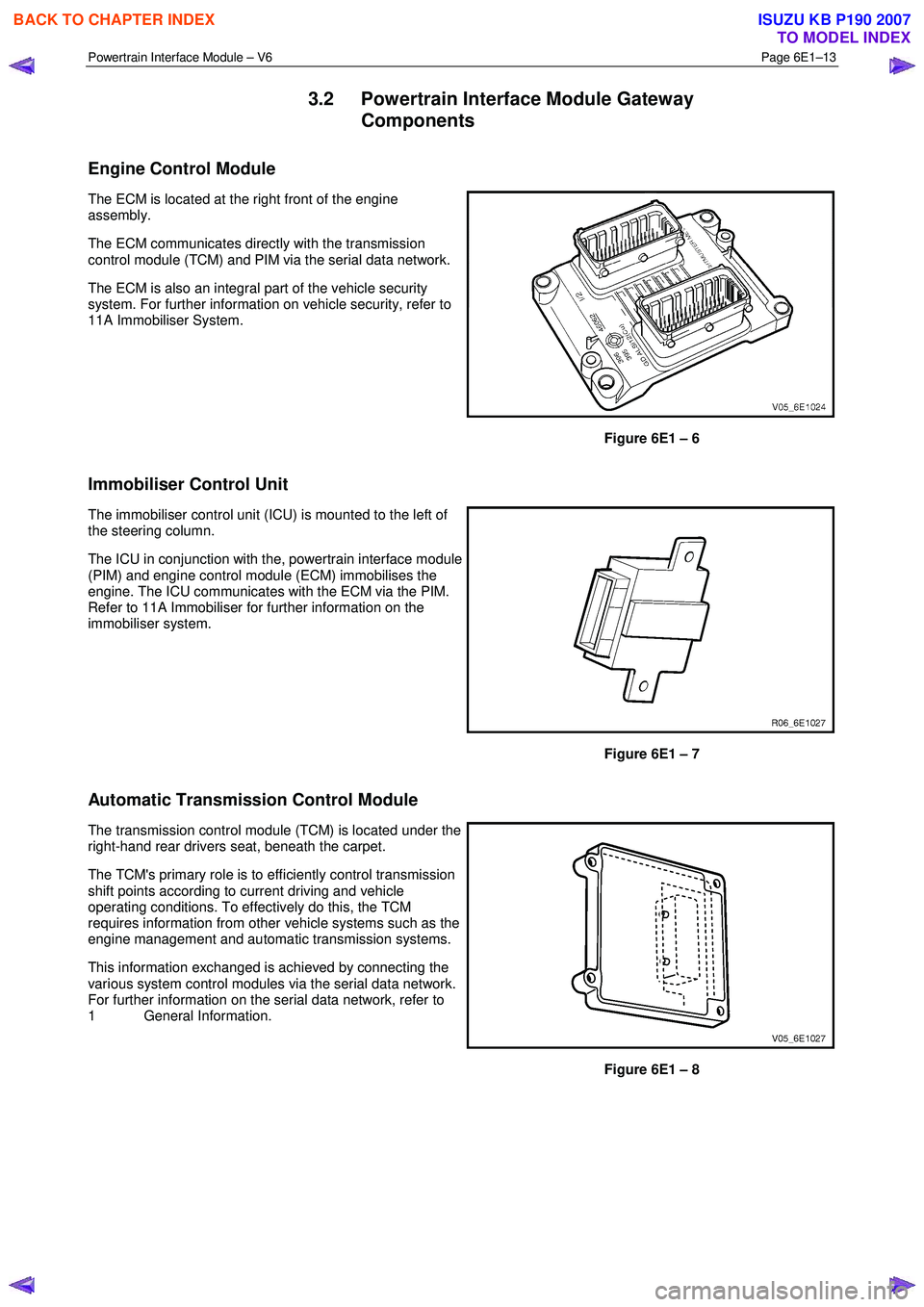
Engine Control Module
The ECM is located at the right front of the engine
assembly.
The ECM communicates directly with the transmission
control module (TCM) and PIM via the serial data network.
The ECM is also an integral part of the vehicle security
system. For further information on vehicle security, refer to
11A Immobiliser System.
Figure 6E1 – 6
Immobiliser Control Unit
The immobiliser control unit (ICU) is mounted to the left of
the steering column.
The ICU in conjunction with the, powertrain interface module
(PIM) and engine control module (ECM) immobilises the
engine. The ICU communicates with the ECM via the PIM.
Refer to 11A Immobiliser for further information on the
immobiliser system.
Figure 6E1 – 7
Automatic Transmission Control Module
The transmission control module (TCM) is located under the
right-hand rear drivers seat, beneath the carpet.
The TCM's primary role is to efficiently control transmission
shift points according to current driving and vehicle
operating conditions. To effectively do this, the TCM
requires information from other vehicle systems such as the
engine management and automatic transmission systems.
This information exchanged is achieved by connecting the
various system control modules via the serial data network.
For further information on the serial data network, refer to
1 General Information.
Figure 6E1 – 8
BACK TO CHAPTER INDEX
TO MODEL INDEX
ISUZU KB P190 2007
Page 3676 of 6020
Powertrain Interface Module – V6 Page 6E1–15
4 Diagnostics
4.1 Diagnostic General Descriptions
The powertrain interface module (PIM) diagnostic procedure is organised in a logical structure that begins with the
Diagnostic System Check. The Diagnostic System Check directs the diagnostic procedure to the logical steps or
appropriate diagnostic table required to diagnose a PIM fault condition.
The diagnostic tables locate a faulty circuit or component through a logical based process of elimination. Correct use of
the diagnostic tables is essential to reduce diagnostic time and to prevent misdiagnosis.
In addition, the Diagnostic System Check provides the following information:
• identification of the PIM,
• condition of the diagnostic circuit, and
• identification and status of the DTCs if present.
Diagnostic Trouble Code (DTC) Tables
The diagnostic procedure is directed to a diagnostic trouble code (DTC) table if there are DTCs currently stored in the
PIM.
The diagnostic tables are designed to locate a faulty circuit or component through a logical based process of elimination.
The diagnostic tables are developed with the following assumptions:
• the vehicle functioned correctly at the time of assembly,
• there are no multiple faults, and
• the problem currently exists.
Multiple DTCs
W hen performing a DTC check and there are multiple DTCs, the diagnostic process must begin with the most likely DTC
that may trigger other DTCs.
Knowledge of the PIM and Tech 2 limitations are important to reduce diagnostic time and to prevent misdiagnosis. Refer
to 7.1 Diagnostic Requirements, Precautions and Preliminary Checks.
Diagnostic Trouble Codes (DTCs)
W hen the ignition switch is turned on, the PIM performs an internal integrity check that detects and isolates any internal
faults. The PIM also monitors the direct input switches such as the cruise control and the serial data bus for messages
from the control modules on the GM LAN bus. If a fault is detected by the PIM, it will log a Diagnostic Trouble Code
(DTC) that represents the fault detected. The DTCs stored in the PIM may be accessed using Tech 2.
Status of DTCs
The PIM designates the DTCs logged into a Current or History DTC.
Current DTCs
If the fault condition that triggers the DTC is present during the last PIM self test, that DTC will be designated as a current
DTC.
History DTCs
If the fault condition that triggers the DTC is not present during the last PIM self test, that DTC will be designated as a
history DTC.
Conditions for Clearing DTCs
• If there is no DTC logged in the current PIM self test, the current DTC will be cleared.
• If there is no DTC logged after 100 consecutive drive cycles, the history DTC will be cleared.
BACK TO CHAPTER INDEX
TO MODEL INDEX
ISUZU KB P190 2007
Page 3690 of 6020

Powertrain Interface Module – V6 Page 6E1–29
Intermittent Fault Conditions
8.1 Intermittent Conditions Diagnostic Table
Description
A fault condition is intermittent if one of the following conditions exists:
• The fault condition is not always present.
• The fault condition cannot be presently duplicated.
• There is no Current DTC but a History DTC is stored.
Diagnostic Table
Checks Actions
Preliminary
• Perform the Preliminary Checks, refer to 7.1 Diagnostic Requirements,
Precautions and Preliminary Checks.
• Gather information from the customer regarding the conditions that trigger the
intermittent fault such as:
• At what engine or ambient temperature range does the fault occur?
• Does the fault occur when operating aftermarket electrical equipment inside
the vehicle?
• Does the fault occur on rough roads or in wet road conditions?
• If the intermittent fault is a start and then stall condition, check immobiliser system.
Refer to 11A Immobiliser.
Harness / Connector Install Tech 2 and perform the Tech 2 Intermittent Fault Tests. Refer to 4.1 Diagnostic General Descriptions for information on Tech 2 ECU diagnostic
tests.
W arning Indicator The following conditions may cause an intermittent Malfunction Indicator Lamp fault with
no DTC listed:
• Electromagnetic Interference (EMI) caused by a faulty relay, ECM controlled
solenoid, switch or other external source.
• Incorrect installation of aftermarket electrical equipment such as the following:
• mobile phones,
• theft deterrent alarms,
• lights, or
• radio equipment.
• Loose PIM ground connections.
BACK TO CHAPTER INDEX
TO MODEL INDEX
ISUZU KB P190 2007
Page 3691 of 6020
Powertrain Interface Module – V6 Page 6E1–30
Checks Actions
Temperature Related The Tech 2 Freeze Frame / Failure Records or Snapshot data may be used if applicable
to the fault condition. Refer to 4.1 Diagnostic General Descriptions for information on
Tech 2 ECU diagnostic tests.
• If the intermittent fault is heat related, review the Tech 2 data in relationship to the
following:
• high ambient temperature,
• underhood / engine generated heat,
• circuit generated heat due to a poor electrical connection or high electrical
load, and
• higher than normal load conditions (towing, etc.).
• If the intermittent fault is related to cold ambient or engine temperature, review the
Tech 2 data in relationship to the following:
• low ambient temperature, and
• the fault condition that occurs only on a cold start situation.
Additional Tests
• Check for incorrect installation of aftermarket electrical equipment such as the
following:
• mobile phones,
• theft deterrent alarms,
• lights, or
• radio equipment.
• Check for electromagnetic Interference (EMI) caused by a faulty relay, ECM
controlled solenoid or switch. The fault is triggered when the relay or solenoid is
activated.
• Check the A/C compressor clutch and some relays that contain a clamping diode
or resistor for an open circuit.
• Check the generator for a faulty rectifier bridge that may allow A/C noise into the
PIM electrical circuit.
When all diagnosis and repairs are completed, check the engine management system for correct operation.
BACK TO CHAPTER INDEX
TO MODEL INDEX
ISUZU KB P190 2007
Page 3710 of 6020
Powertrain Interface Module – V6 Page 6E1–49
9.11 DTC B3902 – Immobiliser Malfunction
DTC Descriptors
This diagnostic procedure supports DTC B3902 – Immobiliser Malfunction.
Circuit Description
The engine control module (ECM), the powertrain interface module (PIM) and the immobiliser control unit (ICU) are
integral parts of the vehicle immobiliser system. The immobiliser system authenticates the security code programmed
into each of these modules to prevent unauthorised vehicle operation. This authentication process includes the following
steps:
1 At predetermined situations, the ICU sends a security code to the PIM.
2 W hen the ignition is switched ON, the PIM receives and compares this security code from the ICU against the security code programmed into the PIM.
3 Once the PIM receives the correct security code from the ICU, it sends a security code to the ECM.
4 The ECM receives and compares this security code from the PIM against the security code programmed into the ECM.
5 The authentication process is complete once the ECM receives the correct security code from the PIM within the specified time frame.
6 The ECM allows normal vehicle operation.
NOTE
If any of these authentication processes fail, the
vehicle will not start and DTCs will set. For further
information on the immobiliser system, refer to
11A Immobiliser.
Conditions for Running the DTC
Conditions for running the DTC are:
• The ignition is switched on.
• The ignition voltage is 10.0 – 16.0 V.
Conditions for Setting the DTC
B3902
Ignition set to the ON position.
Conditions for Clearing the DTC
Refer to 4.1 Diagnostic General Descriptions for information on the conditions for clearing DTCs.
Additional Information
• Refer to 6C1-1 Engine Management –V6 – General Information for details of the ECM operation.
• Refer to 11A Immobiliser for immobiliser system information:
• Refer to 12.4 Immobiliser Link to ECM / PIM for immobiliser link to ECM / PIM.
• Since a fault condition in a wiring connector may trigger DTCs, always test the connectors related to this diagnostic
procedure for shorted terminals or poor wiring connection before replacing any component. Refer to 8A Electrical -
Body and Chassis for information on electrical fault diagnosis.
• For an intermittent fault condition, refer to Intermittent Fault Conditions in this section.
BACK TO CHAPTER INDEX
TO MODEL INDEX
ISUZU KB P190 2007
Page 3714 of 6020
Powertrain Interface Module – V6 Page 6E1–53
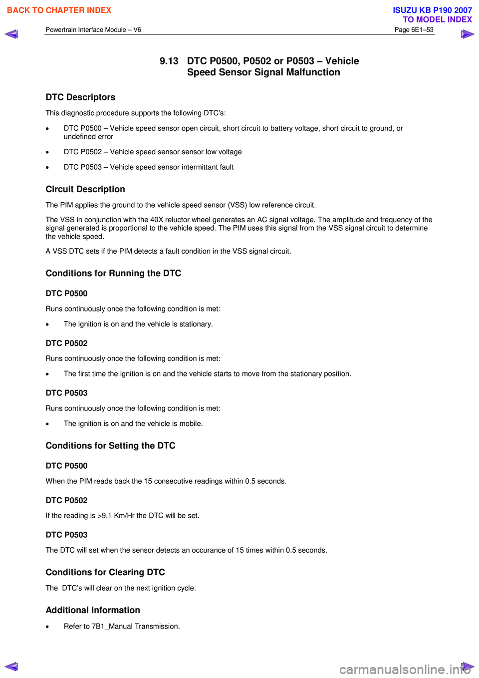
9.13 DTC P0500, P0502 or P0503 – Vehicle
Speed Sensor Signal Malfunction
DTC Descriptors
This diagnostic procedure supports the following DTC’s:
• DTC P0500 – Vehicle speed sensor open circuit, short circuit to battery voltage, short circuit to ground, or
undefined error
• DTC P0502 – Vehicle speed sensor sensor low voltage
• DTC P0503 – Vehicle speed sensor intermittant fault
Circuit Description
The PIM applies the ground to the vehicle speed sensor (VSS) low reference circuit.
The VSS in conjunction with the 40X reluctor wheel generates an AC signal voltage. The amplitude and frequency of the
signal generated is proportional to the vehicle speed. The PIM uses this signal from the VSS signal circuit to determine
the vehicle speed.
A VSS DTC sets if the PIM detects a fault condition in the VSS signal circuit.
Conditions for Running the DTC
DTC P0500
Runs continuously once the following condition is met:
• The ignition is on and the vehicle is stationary.
DTC P0502
Runs continuously once the following condition is met:
• The first time the ignition is on and the vehicle starts to move from the stationary position.
DTC P0503
Runs continuously once the following condition is met:
• The ignition is on and the vehicle is mobile.
Conditions for Setting the DTC
DTC P0500
W hen the PIM reads back the 15 consecutive readings within 0.5 seconds.
DTC P0502
If the reading is >9.1 Km/Hr the DTC will be set.
DTC P0503
The DTC will set when the sensor detects an occurance of 15 times within 0.5 seconds.
Conditions for Clearing DTC
The DTC’s will clear on the next ignition cycle.
Additional Information
• Refer to 7B1_Manual Transmission.
BACK TO CHAPTER INDEX
TO MODEL INDEX
ISUZU KB P190 2007
Page 3716 of 6020
Powertrain Interface Module – V6 Page 6E1–55
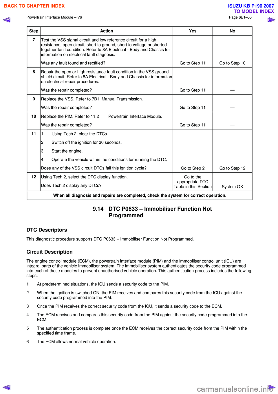
Step Action Yes No
7
Test the VSS signal circuit and low reference circuit for a high
resistance, open circuit, short to ground, short to voltage or shorted
together fault condition. Refer to 8A Electrical - Body and Chassis for
information on electrical fault diagnosis.
W as any fault found and rectified? Go to Step 11 Go to Step 10
8
Repair the open or high resistance fault condition in the VSS ground
shield circuit. Refer to 8A Electrical - Body and Chassis for information
on electrical repair procedures.
W as the repair completed? Go to Step 11 —
9 Replace the VSS. Refer to 7B1_Manual Transmission.
W as the repair completed? Go to Step 11 —
10 Replace the PIM. Refer to 11.2 Powertrain Interface Module.
W as the repair completed? Go to Step 11 —
11 1 Using Tech 2, clear the DTCs.
2 Switch off the ignition for 30 seconds.
3 Start the engine.
4 Operate the vehicle within the conditions for running the DTC.
Does any of the VSS circuit DTCs fail this ignition cycle? Go to Step 2 Go to Step 12
12
Using Tech 2, select the DTC display function.
Does Tech 2 display any DTCs? Go to the
appropriate DTC
Table in this Section System OK
When all diagnosis and repairs are completed, check the system for correct operation.
9.14 DTC P0633 – Immobiliser Function Not
Programmed
DTC Descriptors
This diagnostic procedure supports DTC P0633 – Immobiliser Function Not Programmed.
Circuit Description
The engine control module (ECM), the powertrain interface module (PIM) and the immobiliser control unit (ICU) are
integral parts of the vehicle immobiliser system. The immobiliser system authenticates the security code programmed
into each of these modules to prevent unauthorised vehicle operation. This authentication process includes the following
steps:
1 At predetermined situations, the ICU sends a security code to the PIM.
2 W hen the ignition is switched ON, the PIM receives and compares this security code from the ICU against the security code programmed into the PIM.
3 Once the PIM receives the correct security code from the ICU, it sends a security code to the ECM.
4 The ECM receives and compares this security code from the PIM against the security code programmed into the ECM.
5 The authentication process is complete once the ECM receives the correct security code from the PIM within the specified time frame.
6 The ECM allows normal vehicle operation.
BACK TO CHAPTER INDEX
TO MODEL INDEX
ISUZU KB P190 2007
Page 3718 of 6020
Powertrain Interface Module – V6 Page 6E1–57
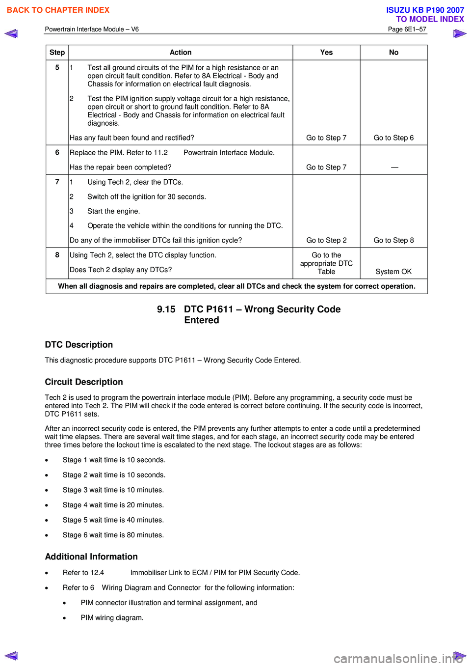
Step Action Yes No
5
1 Test all ground circuits of the PIM for a high resistance or an
open circuit fault condition. Refer to 8A Electrical - Body and
Chassis for information on electrical fault diagnosis.
2 Test the PIM ignition supply voltage circuit for a high resistance, open circuit or short to ground fault condition. Refer to 8A
Electrical - Body and Chassis for information on electrical fault
diagnosis.
Has any fault been found and rectified? Go to Step 7 Go to Step 6
6 Replace the PIM. Refer to 11.2 Powertrain Interface Module.
Has the repair been completed? Go to Step 7 —
7 1 Using Tech 2, clear the DTCs.
2 Switch off the ignition for 30 seconds.
3 Start the engine.
4 Operate the vehicle within the conditions for running the DTC.
Do any of the immobiliser DTCs fail this ignition cycle? Go to Step 2 Go to Step 8
8
Using Tech 2, select the DTC display function.
Does Tech 2 display any DTCs? Go to the
appropriate DTC Table System OK
When all diagnosis and repairs are completed, clear all DTCs and check the system for correct operation.
9.15 DTC P1611 – Wrong Security Code
Entered
DTC Description
This diagnostic procedure supports DTC P1611 – W rong Security Code Entered.
Circuit Description
Tech 2 is used to program the powertrain interface module (PIM). Before any programming, a security code must be
entered into Tech 2. The PIM will check if the code entered is correct before continuing. If the security code is incorrect,
DTC P1611 sets.
After an incorrect security code is entered, the PIM prevents any further attempts to enter a code until a predetermined
wait time elapses. There are several wait time stages, and for each stage, an incorrect security code may be entered
three times before the lockout time is escalated to the next stage. The lockout stages are as follows:
• Stage 1 wait time is 10 seconds.
• Stage 2 wait time is 10 seconds.
• Stage 3 wait time is 10 minutes.
• Stage 4 wait time is 20 minutes.
• Stage 5 wait time is 40 minutes.
• Stage 6 wait time is 80 minutes.
Additional Information
• Refer to 12.4 Immobiliser Link to ECM / PIM for PIM Security Code.
• Refer to 6 W iring Diagram and Connector for the following information:
• PIM connector illustration and terminal assignment, and
• PIM wiring diagram.
BACK TO CHAPTER INDEX
TO MODEL INDEX
ISUZU KB P190 2007