2007 ISUZU KB P190 ECU
[x] Cancel search: ECUPage 3473 of 6020
Engine Management – V6 – Diagnostics Page 6C1-2–195
Action Taken When the DTC Sets
• The control module activates the malfunction indicator lamp (MIL) on the second consecutive ignition cycle that
the diagnostic runs and fails.
• The control module records the operating conditions at the time the diagnostic fails. The first time the diagnostic
fails, the control module stores this information in the Failure Records. If the diagnostic reports a failure on the
second consecutive ignition cycle, the control module records the operating conditions at the time of the failure.
The control module writes the operating conditions to the Freeze Frame and updates the Failure Records.
Conditions for Clearing the MIL/DTC
• The control module turns OFF the malfunction indicator lamp (MIL) after four consecutive ignition cycles that the
diagnostic runs and does not fail.
• A current DTC, Last Test Failed, clears when the diagnostic runs and passes.
• A history DTC clears after 40 consecutive warm-up cycles, if no failures are reported by this or any other emission
related diagnostic.
• Use Tech 2 to clear the MIL and the DTC.
Additional Information
• A fuel delivery condition causes this DTC to set. Thoroughly inspect all items that cause a rich condition.
• For an intermittent fault condition, refer to 5.2 Intermittent Fault Conditions in this Section.
• To assist diagnosis, refer to 3 W iring Diagrams and Connector Charts in this Section, for the system wiring
diagram and connector charts.
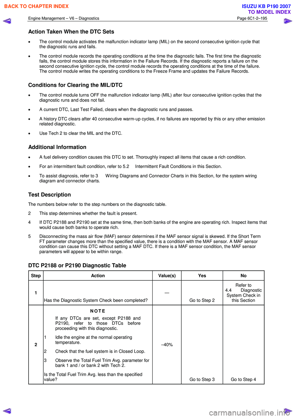
Test Description
The numbers below refer to the step numbers on the diagnostic table.
2 This step determines whether the fault is present.
4 If DTC P2188 and P2190 set at the same time, then both banks of the engine are operating rich. Inspect items that would cause both banks to operate rich.
5 Disconnecting the mass air flow (MAF) sensor determines if the MAF sensor signal is skewed. If the Short Term FT parameter changes more than the specified value, there is a condition with the MAF sensor. A MAF sensor
condition can cause this DTC without setting a MAF DTC. If there is a MAF sensor condition, the MAF sensor
parameters will appear to be within range.
DTC P2188 or P2190 Diagnostic Table
Step Action Value(s) Yes No
1
Has the Diagnostic System Check been completed? —
Go to Step 2 Refer to
4.4 Diagnostic System Check in this Section
2 NOTE
If any DTCs are set, except P2188 and
P2190, refer to those DTCs before
proceeding with this diagnostic.
1 Idle the engine at the normal operating temperature.
2 Check that the fuel system is in Closed Loop.
3 Observe the Total Fuel Trim Avg. parameter for bank 1 and / or bank 2 with Tech 2.
Is the Total Fuel Trim Avg. less than the specified
value? –40%
Go to Step 3 Go to Step 4
BACK TO CHAPTER INDEX
TO MODEL INDEX
ISUZU KB P190 2007
Page 3476 of 6020
Engine Management – V6 – Diagnostics Page 6C1-2–198
• The rear fuel trim, long and short term, is more than a threshold.
• This DTC sets after the air flow coming into the engine accumulates to more than 200 grams and the above
conditions are met for more than 4 seconds.
Condition 2
• The ECM detects that the rear HO2S is operating too rich while the ECM is commanding a lean air / fuel mixture.
• This DTC sets after the air flow coming into the engine accumulates to more than 800 grams and the above
condition is met for more than 4 seconds.
Action Taken When the DTC Sets
• The ECM activates the malfunction indicator lamp (MIL) on the second consecutive ignition cycle that the
diagnostic runs and fails.
• The ECM records the operating conditions at the time the diagnostic fails. The first time the diagnostic fails, the
control module stores this information in the Failure Records. If the diagnostic reports a failure on the second
consecutive ignition cycle, the control module records the operating conditions at the time of the failure. The
control module writes the operating conditions to the Freeze Frame and updates the Failure Records.
Conditions for Clearing the MIL/DTC
• The control module turns OFF the malfunction indicator lamp (MIL) after four consecutive ignition cycles that the
diagnostic runs and does not fail.
• A current DTC, Last Test Failed, clears when the diagnostic runs and passes.
• A history DTC clears after 40 consecutive warm-up cycles, if no failures are reported by this or any other emission
related diagnostic.
• Use Tech 2 to clear the MIL and the DTC.
Additional Information
• A HO2S fault condition may cause this DTC to set. Thoroughly inspect all items that could cause a lean condition.
• For an intermittent fault condition, refer to 5.2 Intermittent Fault Conditions in this Section.
• Since a fault condition in a wiring connector may trigger DTCs, always test the connectors related to this
diagnostic procedure for shorted terminals or poor wiring connection before replacing any component. Refer to 8A
Electrical - Body and Chassis for information on electrical fault diagnosis.
• To assist diagnosis, refer to 3 W iring Diagrams and Connector Charts in this Section, for the system wiring
diagram and connector charts.
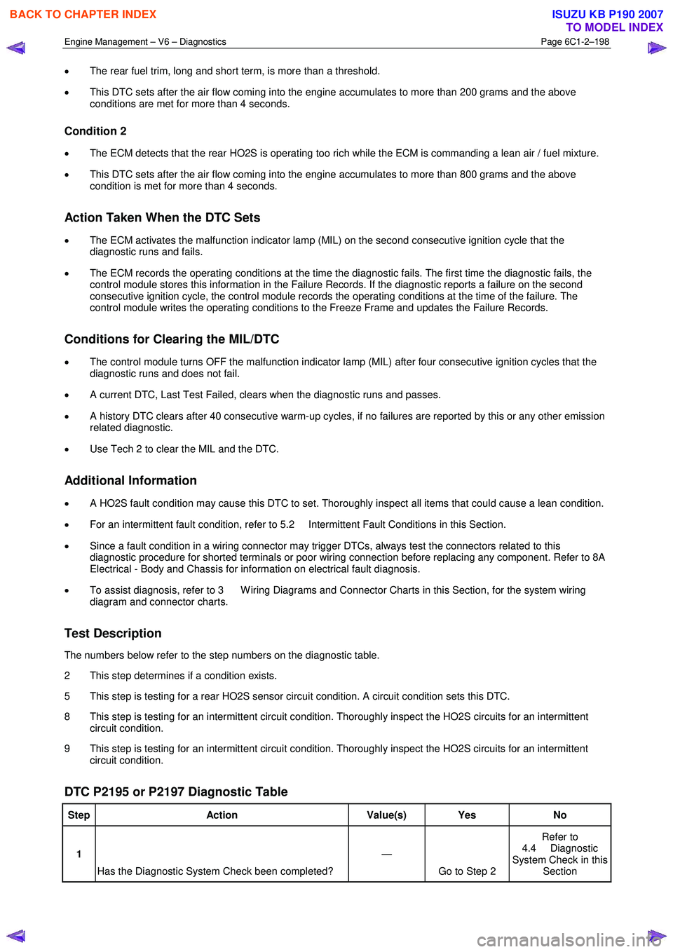
Test Description
The numbers below refer to the step numbers on the diagnostic table.
2 This step determines if a condition exists.
5 This step is testing for a rear HO2S sensor circuit condition. A circuit condition sets this DTC.
8 This step is testing for an intermittent circuit condition. Thoroughly inspect the HO2S circuits for an intermittent circuit condition.
9 This step is testing for an intermittent circuit condition. Thoroughly inspect the HO2S circuits for an intermittent circuit condition.
DTC P2195 or P2197 Diagnostic Table
Step Action Value(s) Yes No
1
Has the Diagnostic System Check been completed? —
Go to Step 2 Refer to
4.4 Diagnostic
System Check in this Section
BACK TO CHAPTER INDEX
TO MODEL INDEX
ISUZU KB P190 2007
Page 3478 of 6020
Engine Management – V6 – Diagnostics Page 6C1-2–200
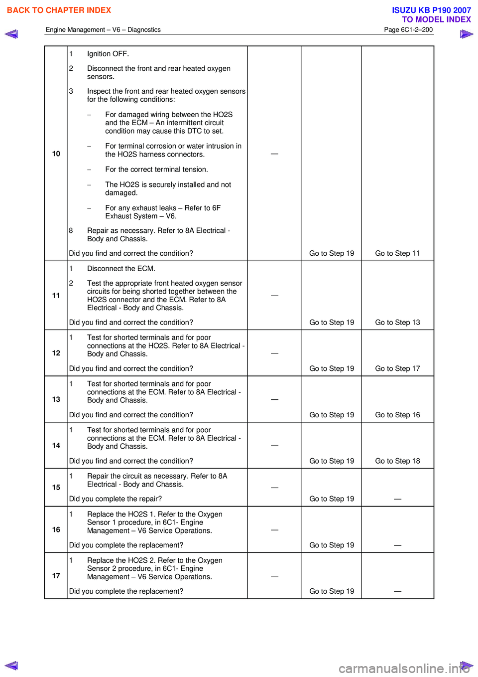
10 1 Ignition OFF.
2 Disconnect the front and rear heated oxygen sensors.
3 Inspect the front and rear heated oxygen sensors for the following conditions:
− For damaged wiring between the HO2S
and the ECM – An intermittent circuit
condition may cause this DTC to set.
− For terminal corrosion or water intrusion in
the HO2S harness connectors.
− For the correct terminal tension.
− The HO2S is securely installed and not
damaged.
− For any exhaust leaks – Refer to 6F
Exhaust System – V6.
8 Repair as necessary. Refer to 8A Electrical - Body and Chassis.
Did you find and correct the condition? —
Go to Step 19 Go to Step 11
11 1 Disconnect the ECM.
2 Test the appropriate front heated oxygen sensor circuits for being shorted together between the
HO2S connector and the ECM. Refer to 8A
Electrical - Body and Chassis.
Did you find and correct the condition? —
Go to Step 19 Go to Step 13
12 1 Test for shorted terminals and for poor
connections at the HO2S. Refer to 8A Electrical -
Body and Chassis.
Did you find and correct the condition? —
Go to Step 19 Go to Step 17
13 1 Test for shorted terminals and for poor
connections at the ECM. Refer to 8A Electrical -
Body and Chassis.
Did you find and correct the condition? —
Go to Step 19 Go to Step 16
14 1 Test for shorted terminals and for poor
connections at the ECM. Refer to 8A Electrical -
Body and Chassis.
Did you find and correct the condition? —
Go to Step 19 Go to Step 18
15 1 Repair the circuit as necessary. Refer to 8A
Electrical - Body and Chassis.
Did you complete the repair? —
Go to Step 19 —
16 1 Replace the HO2S 1. Refer to the Oxygen
Sensor 1 procedure, in 6C1- Engine
Management – V6 Service Operations.
Did you complete the replacement? —
Go to Step 19 —
17 1 Replace the HO2S 2. Refer to the Oxygen
Sensor 2 procedure, in 6C1- Engine
Management – V6 Service Operations.
Did you complete the replacement? —
Go to Step 19 —
BACK TO CHAPTER INDEX
TO MODEL INDEX
ISUZU KB P190 2007
Page 3480 of 6020
Engine Management – V6 – Diagnostics Page 6C1-2–202
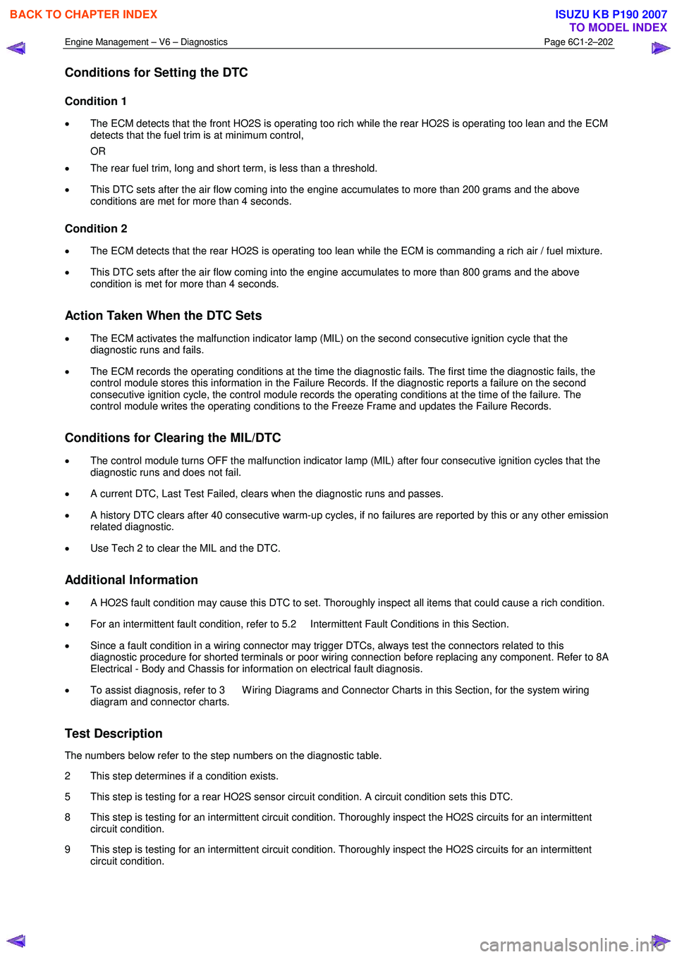
Conditions for Setting the DTC
Condition 1
• The ECM detects that the front HO2S is operating too rich while the rear HO2S is operating too lean and the ECM
detects that the fuel trim is at minimum control,
OR
• The rear fuel trim, long and short term, is less than a threshold.
• This DTC sets after the air flow coming into the engine accumulates to more than 200 grams and the above
conditions are met for more than 4 seconds.
Condition 2
• The ECM detects that the rear HO2S is operating too lean while the ECM is commanding a rich air / fuel mixture.
• This DTC sets after the air flow coming into the engine accumulates to more than 800 grams and the above
condition is met for more than 4 seconds.
Action Taken When the DTC Sets
• The ECM activates the malfunction indicator lamp (MIL) on the second consecutive ignition cycle that the
diagnostic runs and fails.
• The ECM records the operating conditions at the time the diagnostic fails. The first time the diagnostic fails, the
control module stores this information in the Failure Records. If the diagnostic reports a failure on the second
consecutive ignition cycle, the control module records the operating conditions at the time of the failure. The
control module writes the operating conditions to the Freeze Frame and updates the Failure Records.
Conditions for Clearing the MIL/DTC
• The control module turns OFF the malfunction indicator lamp (MIL) after four consecutive ignition cycles that the
diagnostic runs and does not fail.
• A current DTC, Last Test Failed, clears when the diagnostic runs and passes.
• A history DTC clears after 40 consecutive warm-up cycles, if no failures are reported by this or any other emission
related diagnostic.
• Use Tech 2 to clear the MIL and the DTC.
Additional Information
• A HO2S fault condition may cause this DTC to set. Thoroughly inspect all items that could cause a rich condition.
• For an intermittent fault condition, refer to 5.2 Intermittent Fault Conditions in this Section.
• Since a fault condition in a wiring connector may trigger DTCs, always test the connectors related to this
diagnostic procedure for shorted terminals or poor wiring connection before replacing any component. Refer to 8A
Electrical - Body and Chassis for information on electrical fault diagnosis.
• To assist diagnosis, refer to 3 W iring Diagrams and Connector Charts in this Section, for the system wiring
diagram and connector charts.
Test Description
The numbers below refer to the step numbers on the diagnostic table.
2 This step determines if a condition exists.
5 This step is testing for a rear HO2S sensor circuit condition. A circuit condition sets this DTC.
8 This step is testing for an intermittent circuit condition. Thoroughly inspect the HO2S circuits for an intermittent circuit condition.
9 This step is testing for an intermittent circuit condition. Thoroughly inspect the HO2S circuits for an intermittent circuit condition.
BACK TO CHAPTER INDEX
TO MODEL INDEX
ISUZU KB P190 2007
Page 3482 of 6020
Engine Management – V6 – Diagnostics Page 6C1-2–204
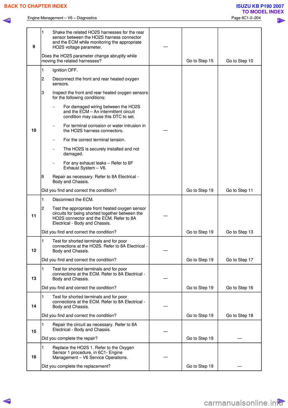
9 1 Shake the related HO2S harnesses for the rear
sensor between the HO2S harness connector
and the ECM while monitoring the appropriate
HO2S voltage parameter.
Does the HO2S parameter change abruptly while
moving the related harnesses? —
Go to Step 15 Go to Step 10
10 1 Ignition OFF.
2 Disconnect the front and rear heated oxygen sensors.
3 Inspect the front and rear heated oxygen sensors for the following conditions:
− For damaged wiring between the HO2S
and the ECM – An intermittent circuit
condition may cause this DTC to set.
− For terminal corrosion or water intrusion in
the HO2S harness connectors.
− For the correct terminal tension.
− The HO2S is securely installed and not
damaged.
− For any exhaust leaks – Refer to 6F
Exhaust System – V6.
8 Repair as necessary. Refer to 8A Electrical - Body and Chassis.
Did you find and correct the condition? —
Go to Step 19 Go to Step 11
11 1 Disconnect the ECM.
2 Test the appropriate front heated oxygen sensor circuits for being shorted together between the
HO2S connector and the ECM. Refer to 8A
Electrical - Body and Chassis.
Did you find and correct the condition? —
Go to Step 19 Go to Step 13
12 1 Test for shorted terminals and for poor
connections at the HO2S. Refer to 8A Electrical -
Body and Chassis.
Did you find and correct the condition? —
Go to Step 19 Go to Step 17
13 1 Test for shorted terminals and for poor
connections at the ECM. Refer to 8A Electrical -
Body and Chassis.
Did you find and correct the condition? —
Go to Step 19 Go to Step 16
14 1 Test for shorted terminals and for poor
connections at the ECM. Refer to 8A Electrical -
Body and Chassis.
Did you find and correct the condition? —
Go to Step 19 Go to Step 18
15 1 Repair the circuit as necessary. Refer to 8A
Electrical - Body and Chassis.
Did you complete the repair? —
Go to Step 19 —
16 1 Replace the HO2S 1. Refer to the Oxygen
Sensor 1 procedure, in 6C1- Engine
Management – V6 Service Operations.
Did you complete the replacement? —
Go to Step 19 —
BACK TO CHAPTER INDEX
TO MODEL INDEX
ISUZU KB P190 2007
Page 3494 of 6020
Engine Management – V6 – Diagnostics Page 6C1-2–216
• The ignition voltage is between 10.7 – 18.0 volts.
• The fuel system is in fuel shut-off mode.
• The calculated exhaust temperature is less than 750°C.
• The heated oxygen sensors are at operating temperature.
• DTC P2626 and P2629 runs continuously once the above conditions are met.
Conditions for Setting the DTC
• The ECM internal HO2S voltage is more than 4.81 volts.
• The condition exists for more than 4 seconds or 600 seconds if the fuel level is less than 12 percent.
Action Taken When the DTC Sets
• The ECM illuminates the malfunction indicator lamp (MIL) on the second consecutive ignition cycle that the
diagnostic runs and fails.
• The control module records the operating conditions at the time the diagnostic fails. The first time the diagnostic
fails, the control module stores this information in the Failure Records. If the diagnostic reports a failure on the
second consecutive ignition cycle, the control module records the operating conditions at the time of the failure.
The control module writes the operating conditions to the Freeze Frame and updates the Failure Records.
Conditions for Clearing the DTC
• The ECM turns OFF the malfunction indicator lamp (MIL) after four consecutive ignition cycles that the diagnostic
runs and does not fail.
• A current DTC, Last Test Failed, clears when the diagnostic runs and passes.
• A history DTC clears after 40 consecutive warm-up cycles, if no failures are reported by this or any other emission
related diagnostic.
• Use Tech 2 to clear the MIL and the DTC.
Additional Information
• Use the J 35616 Connector Test Adapter Kit for any test that requires probing the ECM harness connector or a
component harness connector.
• The lower connector of the ECM is connector A43-X1 and the upper connector of the ECM is connector A43-X2.
Refer to 3 W iring Diagrams and Connector Charts.
• The front wide band sensors do not toggle or switch like a switching HO2S. The front HO2S signals will be
relatively stable for an idling engine.
• For an intermittent fault condition, refer to 5.2 Intermittent Fault Conditions in this Section.
• Since fault condition in a wiring connector may trigger DTCs, always test the connectors related to this diagnostic
procedure for shorted terminals or poor wiring connection before replacing any component. Refer to 8A Electrical-
Body and Chassis for information on electrical fault diagnosis.
• To assist diagnosis, refer to 3 W iring Diagrams and Connector Charts in this Section for the system wiring
diagram and connector charts.
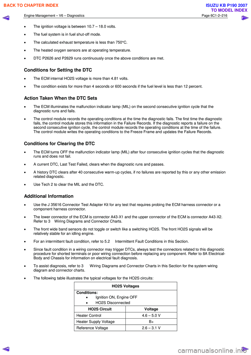
• The following table illustrates the typical voltages for the HO2S circuits:
HO2S Voltages
Conditions: • Ignition ON, Engine OFF
• HO2S Disconnected
HO2S Circuit Voltage
Heater Control 4.6 – 5.0 V
Heater Supply Voltage B+
Reference Voltage 2.6 – 3.1 V
BACK TO CHAPTER INDEX
TO MODEL INDEX
ISUZU KB P190 2007
Page 3503 of 6020
Engine Management – V6 – Diagnostics Page 6C1-2–225
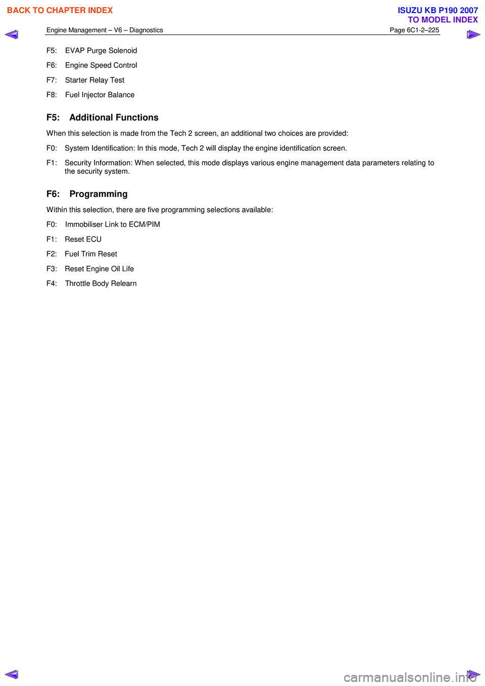
F5: EVAP Purge Solenoid
F6: Engine Speed Control
F7: Starter Relay Test
F8: Fuel Injector Balance
F5: Additional Functions
W hen this selection is made from the Tech 2 screen, an additional two choices are provided:
F0: System Identification: In this mode, Tech 2 will display the engine identification screen.
F1: Security Information: W hen selected, this mode displays various engine management data parameters relating to the security system.
F6: Programming
W ithin this selection, there are five programming selections available:
F0: Immobiliser Link to ECM/PIM
F1: Reset ECU
F2: Fuel Trim Reset
F3: Reset Engine Oil Life
F4: Throttle Body Relearn
BACK TO CHAPTER INDEX
TO MODEL INDEX
ISUZU KB P190 2007
Page 3523 of 6020
Engine Management – V6 – Diagnostics Page 6C1-2–245
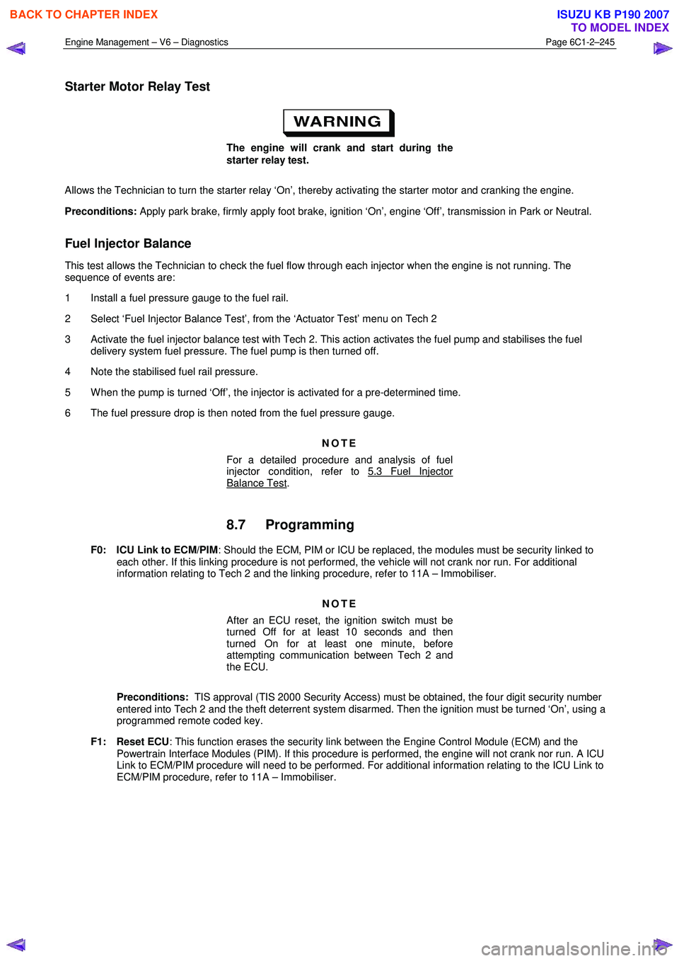
Starter Motor Relay Test
The engine will crank and start during the
starter relay test.
Allows the Technician to turn the starter relay ‘On’, thereby activating the starter motor and cranking the engine.
Preconditions: Apply park brake, firmly apply foot brake, ignition ‘On’, engine ‘Off’, transmission in Park or Neutral.
Fuel Injector Balance
This test allows the Technician to check the fuel flow through each injector when the engine is not running. The
sequence of events are:
1 Install a fuel pressure gauge to the fuel rail.
2 Select ‘Fuel Injector Balance Test’, from the ‘Actuator Test’ menu on Tech 2
3 Activate the fuel injector balance test with Tech 2. This action activates the fuel pump and stabilises the fuel delivery system fuel pressure. The fuel pump is then turned off.
4 Note the stabilised fuel rail pressure.
5 W hen the pump is turned ‘Off’, the injector is activated for a pre-determined time.
6 The fuel pressure drop is then noted from the fuel pressure gauge.
NOTE
For a detailed procedure and analysis of fuel
injector condition, refer to 5.3 Fuel Injector
Balance Test.
8.7 Programming
F0: ICU Link to ECM/PIM : Should the ECM, PIM or ICU be replaced, the modules must be security linked to
each other. If this linking procedure is not performed, the vehicle will not crank nor run. For additional
information relating to Tech 2 and the linking procedure, refer to 11A – Immobiliser.
NOTE
After an ECU reset, the ignition switch must be
turned Off for at least 10 seconds and then
turned On for at least one minute, before
attempting communication between Tech 2 and
the ECU.
Preconditions: TIS approval (TIS 2000 Security Access) must be obtained, the four digit security number
entered into Tech 2 and the theft deterrent system disarmed. Then the ignition must be turned ‘On’, using a
programmed remote coded key.
F1: Reset ECU : This function erases the security link between the Engine Control Module (ECM) and the
Powertrain Interface Modules (PIM). If this procedure is performed, the engine will not crank nor run. A ICU
Link to ECM/PIM procedure will need to be performed. For additional information relating to the ICU Link to
ECM/PIM procedure, refer to 11A – Immobiliser.
BACK TO CHAPTER INDEX
TO MODEL INDEX
ISUZU KB P190 2007