2007 ISUZU KB P190 ECU
[x] Cancel search: ECUPage 3238 of 6020
Fuel System – V6 Page 6C – 36
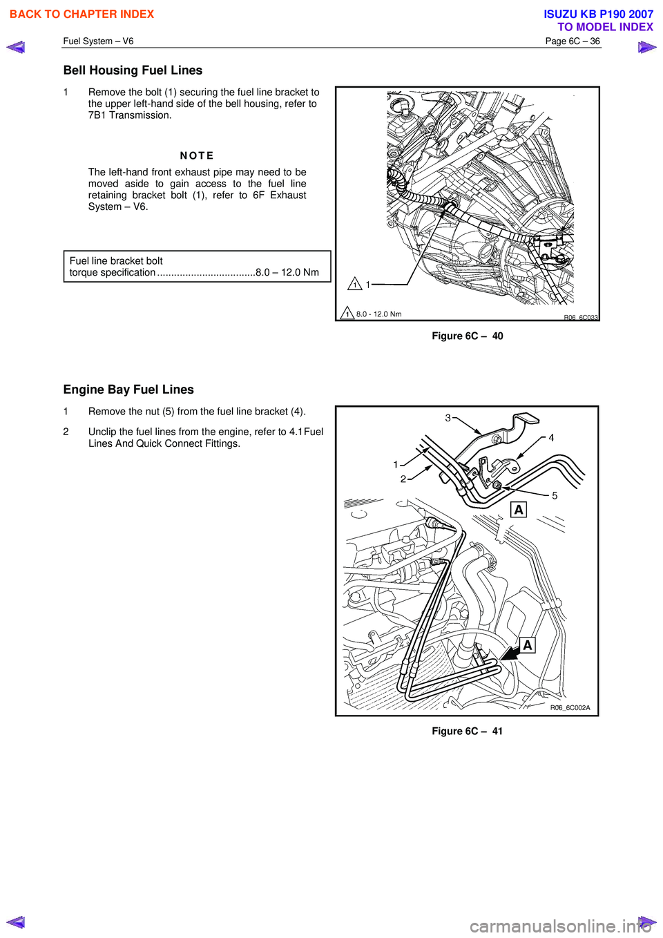
Bell Housing Fuel Lines
1 Remove the bolt (1) securing the fuel line bracket to
the upper left-hand side of the bell housing, refer to
7B1 Transmission.
NOTE
The left-hand front exhaust pipe may need to be
moved aside to gain access to the fuel line
retaining bracket bolt (1), refer to 6F Exhaust
System – V6.
Fuel line bracket bolt
torque specification ...................................8.0 – 12.0 Nm
Figure 6C – 40
Engine Bay Fuel Lines
1 Remove the nut (5) from the fuel line bracket (4).
2 Unclip the fuel lines from the engine, refer to 4.1 Fuel
Lines And Quick Connect Fittings.
Figure 6C – 41
BACK TO CHAPTER INDEX
TO MODEL INDEX
ISUZU KB P190 2007
Page 3241 of 6020
Fuel System – V6 Page 6C – 39
6 Torque Wrench Specifications
Fuel Tank Mounting Strap Bolts ........................................................... 68.0 Nm
Evaporative Emission Control Canister Mounting Nut ................... 2.0 – 5.0 Nm
Fuel Line Securing Nut ................................................................ 8.0 – 12.0 Nm
Stone Guard Securing Bolt ............................................................ 5.0 – 7.0 Nm
BACK TO CHAPTER INDEX
TO MODEL INDEX
ISUZU KB P190 2007
Page 3260 of 6020

Engine Management – V6 – General Information Page 6C1-1–18
3.12 Immobiliser System
The vehicle incorporates an immobiliser system. After the ignition switch is turned to the ON position, and the powertrain
interface module (PIM) has authenticated the immobiliser control unit (ICU), the PIM sends an encrypted security code to
the engine control module (ECM). The ECM compares the received security code with its own security code, and if it is
valid, the ECM enables the vehicle to be started. For further information and diagnosis of the immobiliser system, refer to
11A Immobiliser.
For further information on the PIM, refer to 6E1 Powertrain Interface Module – V6.
BACK TO CHAPTER INDEX
TO MODEL INDEX
ISUZU KB P190 2007
Page 3270 of 6020
Engine Management – V6 – General Information Page 6C1-1–28
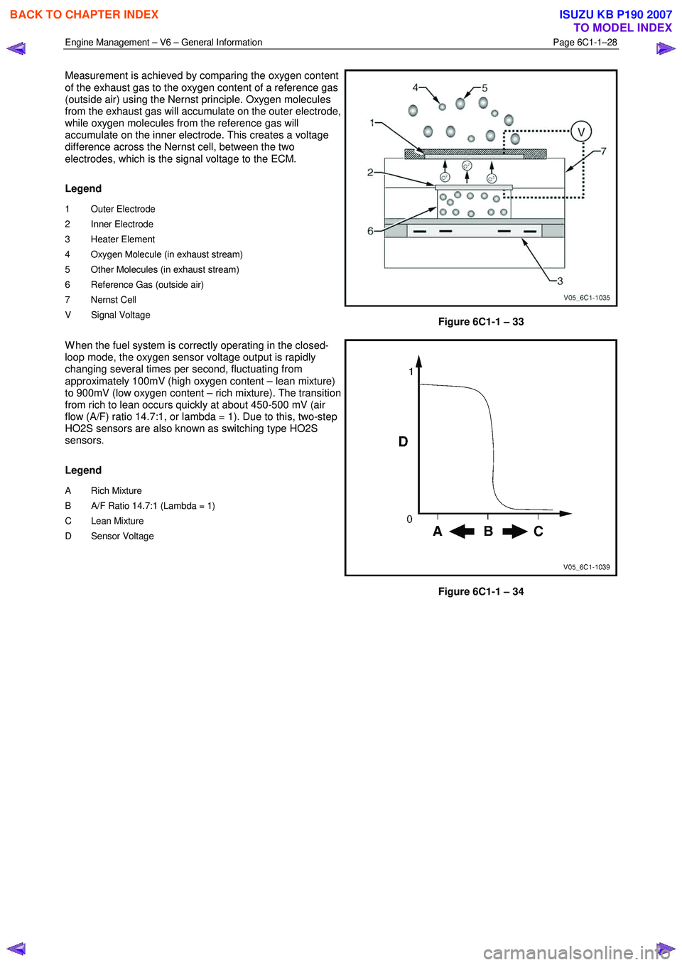
Measurement is achieved by comparing the oxygen content
of the exhaust gas to the oxygen content of a reference gas
(outside air) using the Nernst principle. Oxygen molecules
from the exhaust gas will accumulate on the outer electrode,
while oxygen molecules from the reference gas will
accumulate on the inner electrode. This creates a voltage
difference across the Nernst cell, between the two
electrodes, which is the signal voltage to the ECM.
Legend
1 Outer Electrode
2 Inner Electrode
3 Heater Element
4 Oxygen Molecule (in exhaust stream)
5 Other Molecules (in exhaust stream)
6 Reference Gas (outside air)
7 Nernst Cell
V Signal Voltage
Figure 6C1-1 – 33
W hen the fuel system is correctly operating in the closed-
loop mode, the oxygen sensor voltage output is rapidly
changing several times per second, fluctuating from
approximately 100mV (high oxygen content – lean mixture)
to 900mV (low oxygen content – rich mixture). The transition
from rich to lean occurs quickly at about 450-500 mV (air
flow (A/F) ratio 14.7:1, or lambda = 1). Due to this, two-step
HO2S sensors are also known as switching type HO2S
sensors.
Legend
A Rich Mixture
B A/F Ratio 14.7:1 (Lambda = 1)
C Lean Mixture
D Sensor Voltage
Figure 6C1-1 – 34
BACK TO CHAPTER INDEX
TO MODEL INDEX
ISUZU KB P190 2007
Page 3272 of 6020
Engine Management – V6 – General Information Page 6C1-1–30
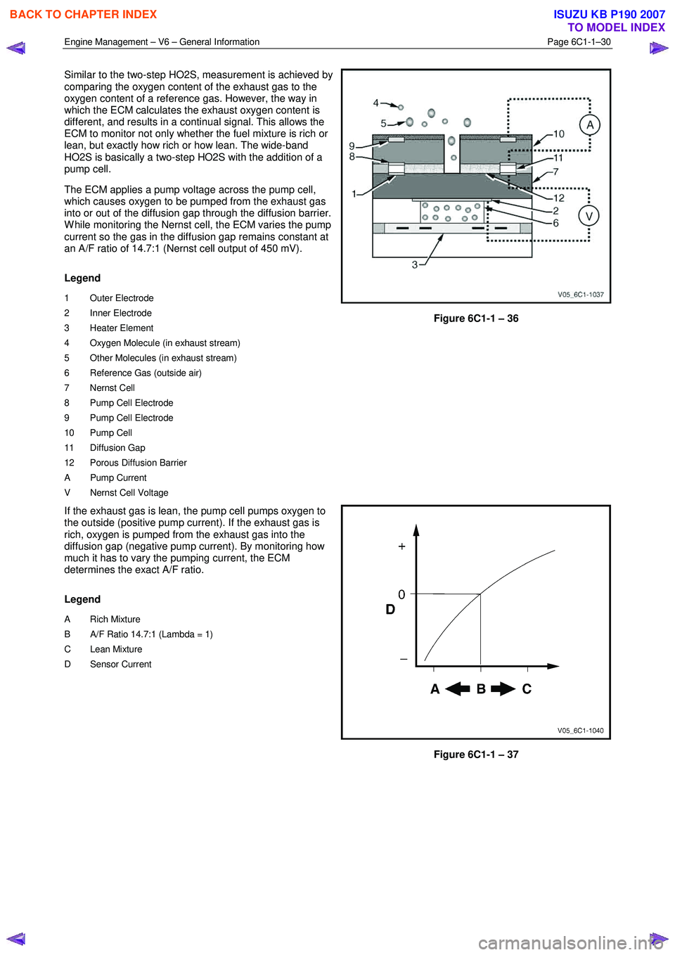
Similar to the two-step HO2S, measurement is achieved by
comparing the oxygen content of the exhaust gas to the
oxygen content of a reference gas. However, the way in
which the ECM calculates the exhaust oxygen content is
different, and results in a continual signal. This allows the
ECM to monitor not only whether the fuel mixture is rich or
lean, but exactly how rich or how lean. The wide-band
HO2S is basically a two-step HO2S with the addition of a
pump cell.
The ECM applies a pump voltage across the pump cell,
which causes oxygen to be pumped from the exhaust gas
into or out of the diffusion gap through the diffusion barrier.
W hile monitoring the Nernst cell, the ECM varies the pump
current so the gas in the diffusion gap remains constant at
an A/F ratio of 14.7:1 (Nernst cell output of 450 mV).
Legend
1 Outer Electrode
2 Inner Electrode
3 Heater Element
4 Oxygen Molecule (in exhaust stream)
5 Other Molecules (in exhaust stream)
6 Reference Gas (outside air)
7 Nernst Cell
8 Pump Cell Electrode
9 Pump Cell Electrode
10 Pump Cell
11 Diffusion Gap
12 Porous Diffusion Barrier
A Pump Current
V Nernst Cell Voltage
Figure 6C1-1 – 36
If the exhaust gas is lean, the pump cell pumps oxygen to
the outside (positive pump current). If the exhaust gas is
rich, oxygen is pumped from the exhaust gas into the
diffusion gap (negative pump current). By monitoring how
much it has to vary the pumping current, the ECM
determines the exact A/F ratio.
Legend
A Rich Mixture
B A/F Ratio 14.7:1 (Lambda = 1)
C Lean Mixture
D Sensor Current
Figure 6C1-1 – 37
BACK TO CHAPTER INDEX
TO MODEL INDEX
ISUZU KB P190 2007
Page 3278 of 6020
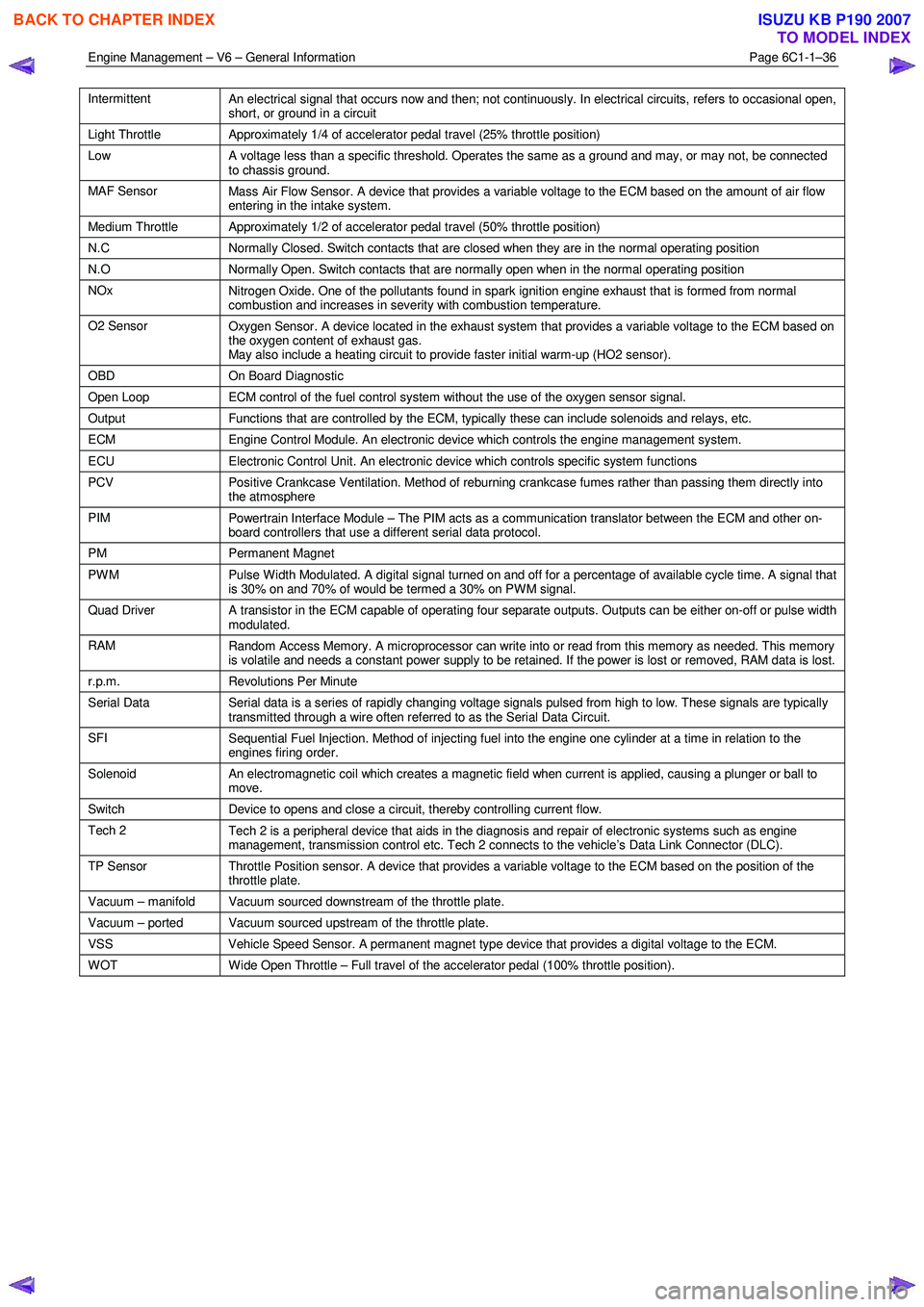
Engine Management – V6 – General Information Page 6C1-1–36
Intermittent
An electrical signal that occurs now and then; not continuously. In electrical circuits, refers to occasional open,
short, or ground in a circuit
Light Throttle Approximately 1/4 of accelerator pedal travel (25% throttle position)
Low
A voltage less than a specific threshold. Operates the same as a ground and may, or may not, be connected
to chassis ground.
MAF Sensor Mass Air Flow Sensor. A device that provides a variable voltage to the ECM based on the amount of air flow
entering in the intake system.
Medium Throttle Approximately 1/2 of accelerator pedal travel (50% throttle position)
N.C Normally Closed. Switch contacts that are closed when they are in the normal operating position
N.O Normally Open. Switch contacts that are normally open when in the normal operating position
NOx
Nitrogen Oxide. One of the pollutants found in spark ignition engine exhaust that is formed from normal
combustion and increases in severity with combustion temperature.
O2 Sensor Oxygen Sensor. A device located in the exhaust system that provides a variable voltage to the ECM based on
the oxygen content of exhaust gas.
May also include a heating circuit to provide faster initial warm-up (HO2 sensor).
OBD On Board Diagnostic
Open Loop ECM control of the fuel control system without the use of the oxygen sensor signal.
Output Functions that are controlled by the ECM, typically these can include solenoids and relays, etc.
ECM Engine Control Module. An electronic device which controls the engine management system.
ECU Electronic Control Unit. An electronic device which controls specific system functions
PCV
Positive Crankcase Ventilation. Method of reburning crankcase fumes rather than passing them directly into
the atmosphere
PIM Powertrain Interface Module – The PIM acts as a communication translator between the ECM and other on-
board controllers that use a different serial data protocol.
PM Permanent Magnet
PWM
Pulse Width Modulated. A digital signal turned on and off for a percentage of available cycle time. A signal that
is 30% on and 70% of would be termed a 30% on PWM signal.
Quad Driver A transistor in the ECM capable of operating four separate outputs. Outputs can be either on-off or pulse width
modulated.
RAM Random Access Memory. A microprocessor can write into or read from this memory as needed. This memory
is volatile and needs a constant power supply to be retained. If the power is lost or removed, RAM data is lost.
r.p.m. Revolutions Per Minute
Serial Data
Serial data is a series of rapidly changing voltage signals pulsed from high to low. These signals are typically
transmitted through a wire often referred to as the Serial Data Circuit.
SFI Sequential Fuel Injection. Method of injecting fuel into the engine one cylinder at a time in relation to the
engines firing order.
Solenoid An electromagnetic coil which creates a magnetic field when current is applied, causing a plunger or ball to
move.
Switch Device to opens and close a circuit, thereby controlling current flow.
Tech 2
Tech 2 is a peripheral device that aids in the diagnosis and repair of electronic systems such as engine
management, transmission control etc. Tech 2 connects to the vehicle’s Data Link Connector (DLC).
TP Sensor Throttle Position sensor. A device that provides a variable voltage to the ECM based on the position of the
throttle plate.
Vacuum – manifold Vacuum sourced downstream of the throttle plate.
Vacuum – ported Vacuum sourced upstream of the throttle plate.
VSS Vehicle Speed Sensor. A permanent magnet type device that provides a digital voltage to the ECM.
WOT Wide Open Throttle – Full travel of the accelerator pedal (100% throttle position).
BACK TO CHAPTER INDEX
TO MODEL INDEX
ISUZU KB P190 2007
Page 3283 of 6020
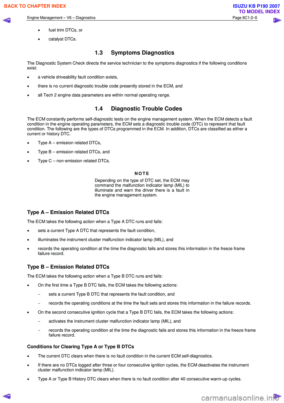
Engine Management – V6 – Diagnostics Page 6C1-2–5
• fuel trim DTCs, or
• catalyst DTCs.
1.3 Symptoms Diagnostics
The Diagnostic System Check directs the service technician to the symptoms diagnostics if the following conditions
exist:
• a vehicle driveability fault condition exists,
• there is no current diagnostic trouble code presently stored in the ECM, and
• all Tech 2 engine data parameters are within normal operating range.
1.4 Diagnostic Trouble Codes
The ECM constantly performs self-diagnostic tests on the engine management system. W hen the ECM detects a fault
condition in the engine operating parameters, the ECM sets a diagnostic trouble code (DTC) to represent that fault
condition. The following are the types of DTCs programmed in the ECM. In addition, DTCs are classified as either a
current or history DTC.
• Type A – emission related DTCs,
• Type B – emission related DTCs, and
• Type C – non-emission related DTCs.
NOTE
Depending on the type of DTC set, the ECM may
command the malfunction indicator lamp (MIL) to
illuminate and warn the driver there is a fault in
the engine management system.
Type A – Emission Related DTCs
The ECM takes the following action when a Type A DTC runs and fails:
• sets a current Type A DTC that represents the fault condition,
• illuminates the instrument cluster malfunction indicator lamp (MIL), and
• records the operating condition at the time the diagnostic fails and stores this information in the freeze frame
failure record.
Type B – Emission Related DTCs
The ECM takes the following action when a Type B DTC runs and fails:
• On the first time a Type B DTC fails, the ECM takes the following actions:
− sets a current Type B DTC that represents the fault condition, and
− records the operating conditions at the time the fault sets and stores this information in the failure records.
• On the second consecutive ignition cycle that a Type B DTC fails, the ECM takes the following actions:
− activates the instrument cluster malfunction indicator lamp (MIL), and
− records the operating condition at the time the diagnostic fails and stores this information in the freeze frame
failure record.
Conditions for Clearing Type A or Type B DTCs
• The current DTC clears when there is no fault condition in the current ECM self-diagnostics.
• If there are no DTCs logged after three or four consecutive ignition cycles, the ECM deactivates the instrument
cluster malfunction indicator lamp (MIL).
• Type A or Type B History DTC clears when there is no fault condition after 40 consecutive warm-up cycles.
BACK TO CHAPTER INDEX
TO MODEL INDEX
ISUZU KB P190 2007
Page 3284 of 6020
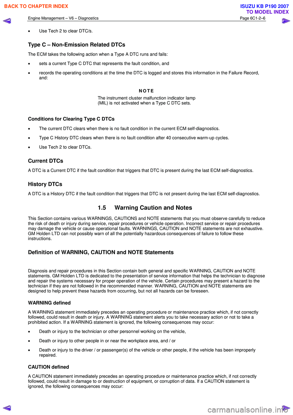
Engine Management – V6 – Diagnostics Page 6C1-2–6
• Use Tech 2 to clear DTC/s.
Type C – Non-Emission Related DTCs
The ECM takes the following action when a Type A DTC runs and fails:
• sets a current Type C DTC that represents the fault condition, and
• records the operating conditions at the time the DTC is logged and stores this information in the Failure Record,
and:
NOTE
The instrument cluster malfunction indicator lamp
(MIL) is not activated when a Type C DTC sets.
Conditions for Clearing Type C DTCs
• The current DTC clears when there is no fault condition in the current ECM self-diagnostics.
• Type C History DTC clears when there is no fault condition after 40 consecutive warm-up cycles.
• Use Tech 2 to clear DTCs.
Current DTCs
A DTC is a Current DTC if the fault condition that triggers that DTC is present during the last ECM self-diagnostics.
History DTCs
A DTC is a History DTC if the fault condition that triggers that DTC is not present during the last ECM self-diagnostics.
1.5 Warning Caution and Notes
This Section contains various W ARNINGS, CAUTIONS and NOTE statements that you must observe carefully to reduce
the risk of death or injury during service, repair procedures or vehicle operation. Incorrect service or repair procedures
may damage the vehicle or cause operational faults. W ARNINGS, CAUTION and NOTE statements are not exhaustive.
GM Holden LTD can not possibly warn of all the potentially hazardous consequences of failure to follow these
instructions.
Definition of WARNING, CAUTION and NOTE Statements
Diagnosis and repair procedures in this Section contain both general and specific W ARNING, CAUTION and NOTE
statements. GM Holden LTD is dedicated to the presentation of service information that helps the technician to diagnose
and repair the systems necessary for proper operation of the vehicle. Certain procedures may present a hazard to the
technician if they are not followed in the recommended manner. W ARNING, CAUTION and NOTE statements are
designed to help prevent these hazards from occurring, but not all hazards can be foreseen.
WARNING defined
A W ARNING statement immediately precedes an operating procedure or maintenance practice which, if not correctly
followed, could result in death or injury. A W ARNING statement alerts you to take necessary action or not to take a
prohibited action. If a W ARNING statement is ignored, the following consequences may occur:
• Death or injury to the technician or other personnel working on the vehicle,
• Death or injury to other people in or near the workplace area, and / or
• Death or injury to the driver / or passenger(s) of the vehicle or other people, if the vehicle has been improperly
repaired.
CAUTION defined
A CAUTION statement immediately precedes an operating procedure or maintenance practice which, if not correctly
followed, could result in damage to or destruction of equipment, or corruption of data. If a CAUTION statement is
ignored, the following consequences may occur:
BACK TO CHAPTER INDEX
TO MODEL INDEX
ISUZU KB P190 2007