Page 2428 of 6020
6E–258 ENGINE DRIVEABILITY AND EMISSIONS
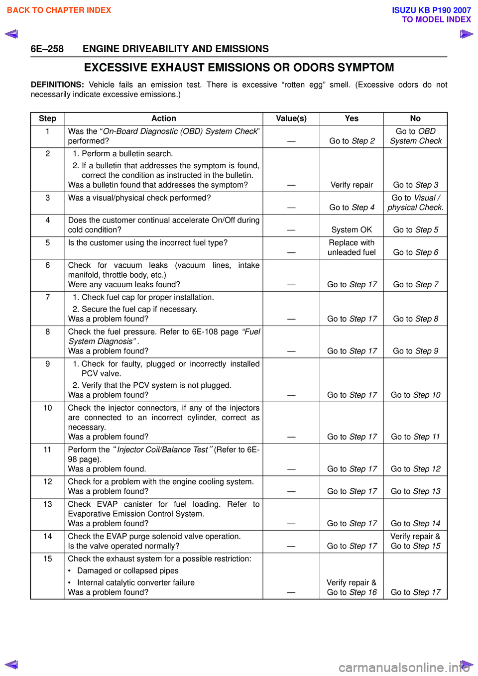
EXCESSIVE EXHAUST EMISSIONS OR ODORS SYMPTOM
DEFINITIONS: Vehicle fails an emission test. There is excessive “rotten egg” smell. (Excessive odors do not
necessarily indicate excessive emissions.)
Step Action Value(s) Yes No
1 Was the “ On-Board Diagnostic (OBD) System Check ”
performed? — Go to Step 2Go to
OBD
System Check
2 1. Perform a bulletin search. 2. If a bulletin that addresses the symptom is found,correct the condition as instructed in the bulletin.
Was a bulletin found that addresses the symptom? — Verify repair Go to Step 3
3 Was a visual/physical check performed? —Go to Step 4Go to
Visual /
physical Check .
4 Does the customer continual accelerate On/Off during cold condition? — System OK Go to Step 5
5 Is the customer using the incorrect fuel type? —Replace with
unleaded fuel Go to Step 6
6 Check for vacuum leaks (vacuum lines, intake manifold, throttle body, etc.)
Were any vacuum leaks found? — Go to Step 17Go to Step 7
7 1. Check fuel cap for proper installation. 2. Secure the fuel cap if necessary.
Was a problem found? — Go to Step 17Go to Step 8
8 Check the fuel pressure. Refer to 6E-108 page “Fuel
System Diagnosis” .
Was a problem found? — Go to Step 17Go to Step 9
9 1. Check for faulty, plugged or incorrectly installed PCV valve.
2. Verify that the PCV system is not plugged.
Was a problem found? — Go to Step 17Go to Step 10
10 Check the injector connectors, if any of the injectors are connected to an incorrect cylinder, correct as
necessary.
Was a problem found? — Go to Step 17Go to Step 11
11 Perform the “Injector Coil/Balance Test
” (Refer to 6E-
98 page).
Was a problem found. — Go to Step 17Go to Step 12
12 Check for a problem with the engine cooling system. Was a problem found? — Go to Step 17Go to Step 13
13 Check EVAP canister for fuel loading. Refer to Evaporative Emission Control System.
Was a problem found? — Go to Step 17Go to Step 14
14 Check the EVAP purge solenoid valve operation. Is the valve operated normally? — Go to Step 17Verify repair &
Go to Step 15
15 Check the exhaust system for a possible restriction: • Damaged or collapsed pipes
• Internal catalytic converter failure
Was a problem found? —Verify repair &
Go to Step 16 Go to Step 17
BACK TO CHAPTER INDEX
TO MODEL INDEX
ISUZU KB P190 2007
Page 2441 of 6020
ENGINE DRIVEABILITY AND EMISSIONS 6E–271
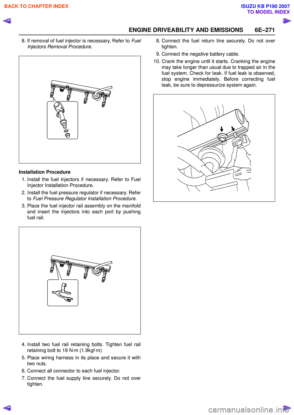
8. If removal of fuel injector is necessary, Refer to Fuel
Injectors Removal Procedure .
Installation Procedure 1. Install the fuel injectors if necessary. Refer to Fuel Injector Installation Procedure.
2. Install the fuel pressure regulator if necessary. Refer to Fuel Pressure Regulator Installation Procedure .
3. Place the fuel injector rail assembly on the manifold and insert the injectors into each port by pushing
fuel rail.
4. Install two fuel rail retaining bolts. Tighten fuel rail retaining bolt to 19 N·m (1.9kgf·m)
5. Place wiring harness in its place and secure it with two nuts.
6. Connect all connector to each fuel injector.
7. Connect the fuel supply line securely. Do not over tighten. 8. Connect the fuel return line securely. Do not over
tighten.
9. Connect the negative battery cable.
10. Crank the engine until it starts. Cranking the engine may take longer than usual due to trapped air in the
fuel system. Check for leak. If fuel leak is observed,
stop engine immediately. Before correcting fuel
leak, be sure to depressurize system again.
BACK TO CHAPTER INDEX
TO MODEL INDEX
ISUZU KB P190 2007
Page 2547 of 6020
Engine Mechanical – V6 Page 6A1–68
CAUTION
Tighten the intake manifold bolts in a circular
pattern starting at the centre bolt and moving
outward.
2 Ensure that all fasteners are tightened to the correct torque specification. Upper intake manifold to lower
intake manifold attaching bolt
torque specification ............................................23.0 Nm
Upper intake manifold to
cylinder head attaching bolt
torque specification ............................................23.0 Nm
Incorrect wiring connector installation may
cause component malfunction or component
damage.
3 Ensure all wiring connectors are fully engaged and if applicable, locked in place.
4 Ensure all wiring harnesses are correctly routed and attached securely in their retaining clips.
5 Ensure that all hoses and pipes are routed correctly and that any retaining clips are correctly installed.
6 Start and run the engine to check for correct operation.
3.10 Intake Manifold Assembly – Complete
The intake manifold comprises of an upper and lower section. Some service procedures only require the removal of the
upper intake manifold (e.g. fuel injector/spark plug servicing), while other service procedures require the removal of both
the upper and lower manifold as a complete assembly (e.g. cylinder head/s). If only the upper intake manifold needs to
be removed, refer to 3.9 Upper Intake Manifold.
Remove
Disconnection of the battery affects certain
vehicle electronic systems. Refer to 1.1
WARNING, CAUTION and NOTES before
disconnecting the battery.
1 Depressurise the fuel system.
2 Disconnect the battery negative terminal.
BACK TO CHAPTER INDEX
TO MODEL INDEX
ISUZU KB P190 2007
Page 2551 of 6020
Engine Mechanical – V6 Page 6A1–72
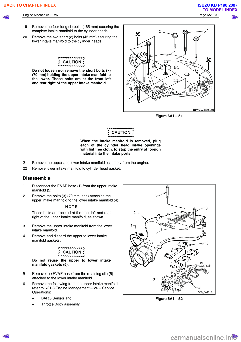
19 Remove the four long (1) bolts (165 mm) securing the
complete intake manifold to the cylinder heads.
20 Remove the two short (2) bolts (45 mm) securing the lower intake manifold to the cylinder heads.
Do not loosen nor remove the short bolts ( �8
�8�8
�8
)
(70 mm) holding the upper intake manifold to
the lower. These bolts are at the front left
and rear right of the upper intake manifold.
Figure 6A1 – 51
When the intake manifold is removed, plug
each of the cylinder head intake openings
with lint free cloth, to stop the entry of foreign
material into the intake ports.
21 Remove the upper and lower intake manifold assembly from the engine.
22 Remove lower intake manifold to cylinder head gasket.
Disassemble
1 Disconnect the EVAP hose (1) from the upper intake manifold (2).
2 Remove the bolts (3) (70 mm long) attaching the upper intake manifold to the lower intake manifold (4).
NOTE
These bolts are located at the front left and rear
right of the upper intake manifold, as shown.
3 Remove the upper intake manifold from the lower intake manifold.
4 Remove and discard the upper to lower intake manifold gaskets.
Do not reuse the upper to lower intake
manifold gaskets (5).
5 Remove the EVAP hose from the retaining clip (6) attached to the lower intake manifold.
6 Remove the following from the upper intake manifold, refer to 6C1-3 Engine Management – V6 – Service
Operations:
• BARO Sensor and
• Throttle Body assembly
Figure 6A1 – 52
BACK TO CHAPTER INDEX
TO MODEL INDEX
ISUZU KB P190 2007
Page 2554 of 6020
Engine Mechanical – V6 Page 6A1–75
CAUTION
Tighten the intake manifold bolts in a circular
pattern starting at the centre bolt and moving
outward.
4 Ensure that all fasteners are tightened to the correct torque specification. Upper intake manifold to lower intake
manifold attaching bolt torque specification .......23.0 Nm
Upper intake manifold to cylinder
head attaching bolt torque specification .............23.0 Nm
Lower intake manifold to cylinder
head attaching bolt torque specification .............23.0 Nm
Fuel injector wiring harness bracket
attaching bolt torque specification ........................9.0 Nm
Incorrect wiring connector installation may
cause component malfunction or component
damage.
5 Ensure all wiring connectors are fully engaged and if applicable, locked in place.
6 Ensure all wiring harnesses are correctly routed and attached securely in their retaining clips.
7 Ensure that all hoses and pipes are routed correctly and that any retaining clips are correctly installed.
8 After installation pull on any quick connect fittings to check that each is correctly installed.
9 Start and run the engine to check for correct operation.
3.11 Exhaust Manifold Assembly
Remove
Allow the engine to cool before commencing.
Disconnection of the battery affects certain
vehicle electronic systems, refer to 1.1
WARNING, CAUTION and NOTES before
disconnecting the battery.
1 Disconnect the battery negative terminal.
BACK TO CHAPTER INDEX
TO MODEL INDEX
ISUZU KB P190 2007
Page 2657 of 6020
Engine Mechanical – V6 Page 6A1–178
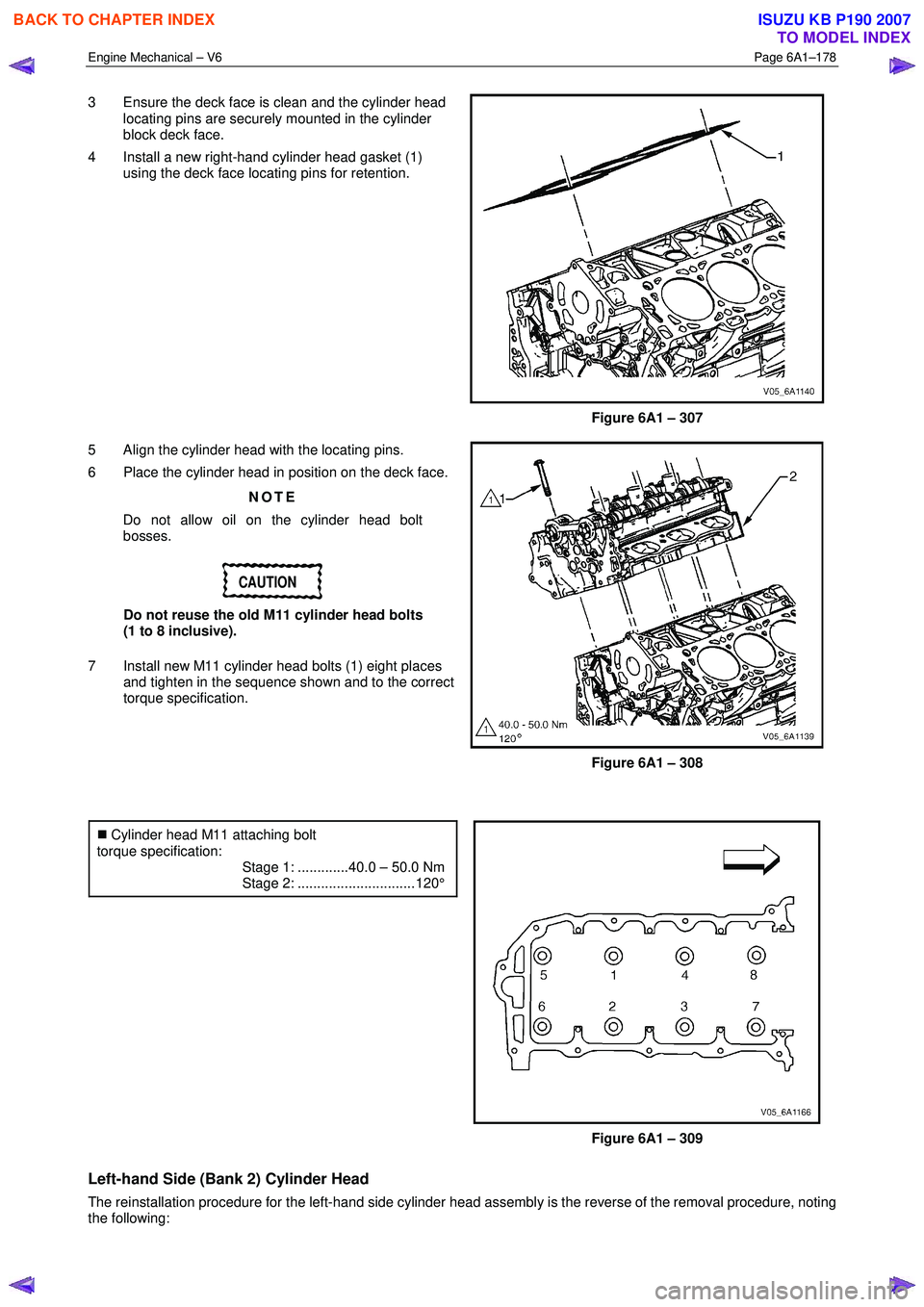
3 Ensure the deck face is clean and the cylinder head
locating pins are securely mounted in the cylinder
block deck face.
4 Install a new right-hand cylinder head gasket (1) using the deck face locating pins for retention.
Figure 6A1 – 307
5 Align the cylinder head with the locating pins.
6 Place the cylinder head in position on the deck face.
NOTE
Do not allow oil on the cylinder head bolt
bosses.
CAUTION
Do not reuse the old M11 cylinder head bolts
(1 to 8 inclusive).
7 Install new M11 cylinder head bolts (1) eight places and tighten in the sequence shown and to the correct
torque specification.
Figure 6A1 – 308
�„ Cylinder head M11 attaching bolt
torque specification:
Stage 1: .............40.0 – 50.0 Nm
Stage 2: .............................. 120°
Figure 6A1 – 309
Left-hand Side (Bank 2) Cylinder Head
The reinstallation procedure for the left-hand side cylinder head assembly is the reverse of the removal procedure, noting
the following:
BACK TO CHAPTER INDEX
TO MODEL INDEX
ISUZU KB P190 2007
Page 2658 of 6020
Engine Mechanical – V6 Page 6A1–179
1 Ensure all fasteners are tightened to the correct torque specification.
2 Using crankshaft rotation Tool No. EN-46111 (1), align the crankshaft sprocket timing mark (2) with the
indexing mark (3) on the oil pump housing.
Figure 6A1 – 310
3 Ensure the deck face is clean and the cylinder head locating pins are securely mounted in the cylinder
block deck face.
4 Install a new cylinder head gasket (1) using the deck face locating pins for retention.
Figure 6A1 – 311
5 Align the cylinder head with the locating pins.
6 Place the cylinder head in position on the deck face.
NOTE
Do not allow oil on the cylinder head bolt
bosses.
CAUTION
Do not reuse the old M11 cylinder head bolts
(1 to 8 inclusive).
7 Install new M11 cylinder head bolt (1), eight places, and tighten in the sequence shown and to the correct
torque specification.
Figure 6A1 – 312
BACK TO CHAPTER INDEX
TO MODEL INDEX
ISUZU KB P190 2007
Page 2703 of 6020
Engine Mechanical – V6 Page 6A1–224
4 Loosen the nuts (1) of the crankshaft main bearing
cap remover, Tool No. J-41818 (2) to separate the
chamfered collets. Install the collets into the inner bolt
holes of the front main bearing cap (3).
5 Tighten the remover nuts to the correct torque specification.
Crankshaft bearing cap remover nut .................11.0 Nm.
6 Install a slide hammer, Tool No. J-6125-1B (4) onto the crankshaft bearing cap remover and remove the
crankshaft bearing cap.
7 Repeat steps 9 to 14 for the remaining crankshaft bearing caps.
Figure 6A1 – 411
8 Remove the crankshaft (1) from the engine block (2), lifting evenly to avoid jamming against the main thrust
bearing.
9 Place the crankshaft in a secure place.
Figure 6A1 – 412
10 If required, remove the crankshaft sprocket drive pin (1) from the crankshaft (2),
Figure 6A1 – 413
BACK TO CHAPTER INDEX
TO MODEL INDEX
ISUZU KB P190 2007