Page 2859 of 6020
Engine Mechanical – V6 Page 6A1–82
Page 6A1–82
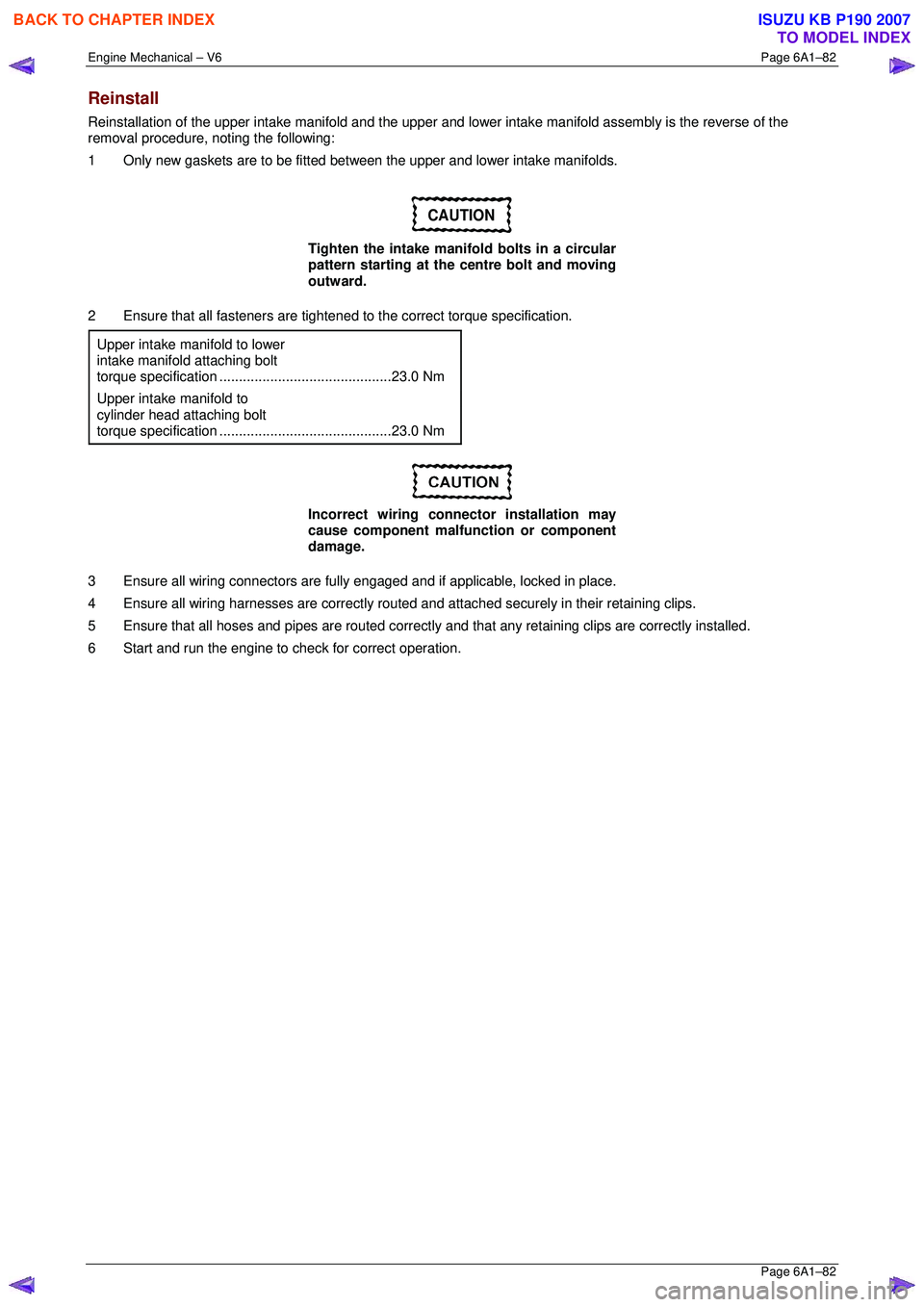
Reinstall
Reinstallation of the upper intake manifold and the upper and lower intake manifold assembly is the reverse of the
removal procedure, noting the following:
1 Only new gaskets are to be fitted betw een the upper and lower intake manifolds.
CAUTION
Tighten the intake manifold bolts in a circular
pattern starting at the centre bolt and moving
outward.
2 Ensure that all fasteners are tightened to the correct torque specification.
Upper intake manifold to lower
intake manifold attaching bolt
torque specificat ion ............................................ 23.0 Nm
Upper intake manifold to
cylinder head attaching bolt
torque specification ............................................ 23.0 Nm
Incorrect wiring connector installation may
cause component malfunction or component
damage.
3 Ensure all wiring connectors are fully engaged and if applicable, locked in place.
4 Ensure all wiring harnesses are correctly routed and attached securely in their retaining clips.
5 Ensure that all hoses and pipes ar e routed correctly and that any retaining clips are correctly installed.
6 Start and run the engine to c heck for correct operation.
BACK TO CHAPTER INDEX
TO MODEL INDEX
ISUZU KB P190 2007
Page 2863 of 6020
Engine Mechanical – V6 Page 6A1–86
Page 6A1–86
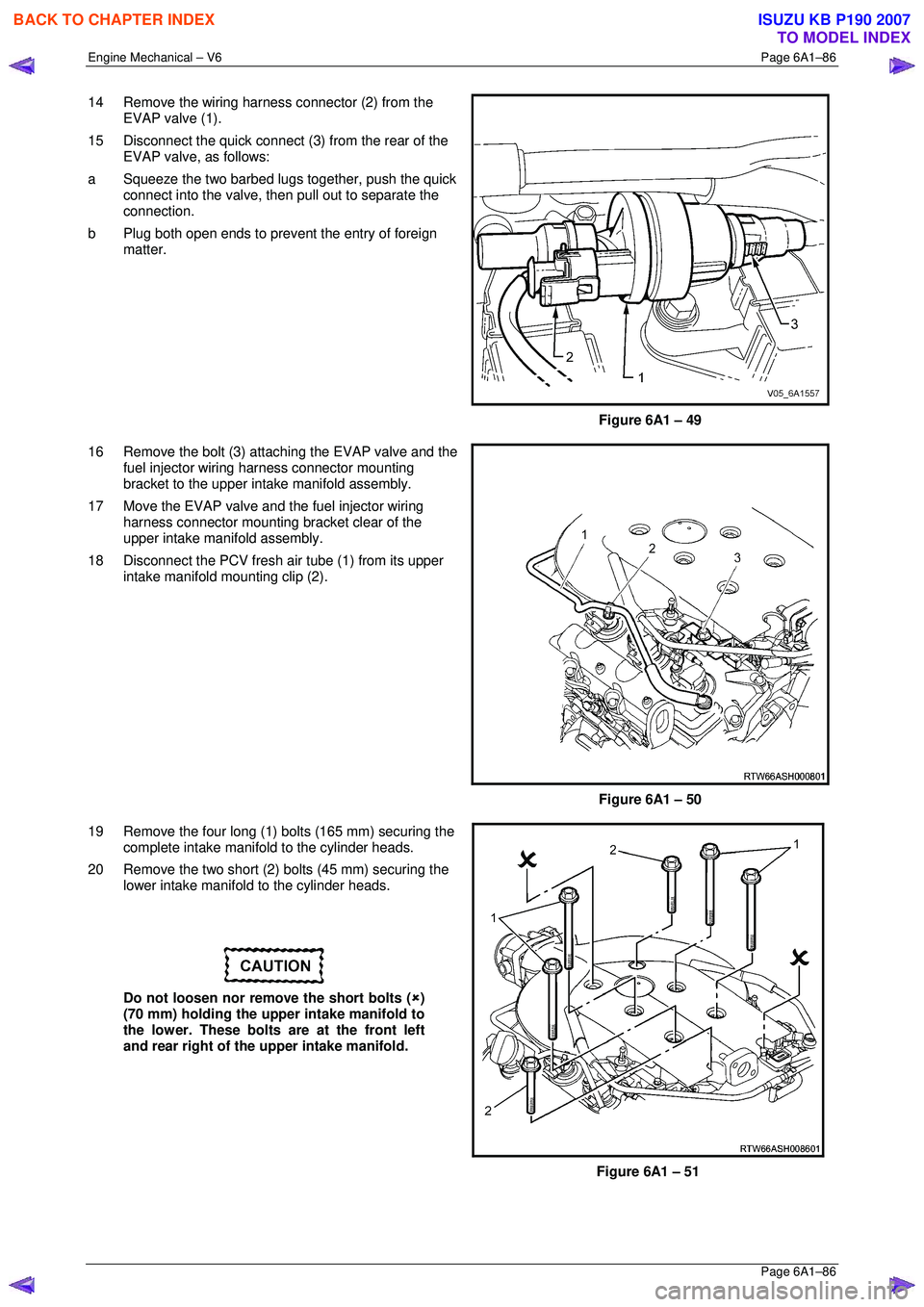
14 Remove the wiring harness connector (2) from the
EVAP valve (1).
15 Disconnect the quick connect (3 ) from the rear of the
EVAP valve, as follows:
a Squeeze the two barbed lugs together, push the quick
connect into the valve, t hen pull out to separate the
connection.
b Plug both open ends to prevent the entry of foreign
matter.
Figure 6A1 – 49
16 Remove the bolt (3) attaching the EVAP valve and the fuel injector wiring harness connector mounting
bracket to the upper inta ke manifold assembly.
17 Move the EVAP valve and the fuel injector wiring harness connector mounting bracket clear of the
upper intake manifold assembly.
18 Disconnect the PCV fresh air tube (1) from its upper intake manifold mounting clip (2).
Figure 6A1 – 50
19 Remove the four long (1) bolts (165 mm) securing the complete intake manifo ld to the cylinder heads.
20 Remove the two short (2) bolts (45 mm) securing the lower intake manifold to the cylinder heads.
Do not loosen nor remove the short bolts ( �8)
(70 mm) holding the upper intake manifold to
the lower. These bolts are at the front left
and rear right of the upper intake manifold.
Figure 6A1 – 51
BACK TO CHAPTER INDEX
TO MODEL INDEX
ISUZU KB P190 2007
Page 2867 of 6020
Engine Mechanical – V6 Page 6A1–90
Page 6A1–90
5 Ensure all wiring connectors are fully engaged and if applicable, locked in place.
6 Ensure all wiring harnesses are correctly routed and attached securely in their retaining clips.
7 Ensure that all hoses and pipes ar e routed correctly and that any retaining clips are correctly installed.
8 After installation pull on any quick connect fittings to check that each is correctly installed.
9 Start and run the engine to c heck for correct operation.
BACK TO CHAPTER INDEX
TO MODEL INDEX
ISUZU KB P190 2007
Page 3010 of 6020
Engine Mechanical – V6 Page 6A1–233
Page 6A1–233
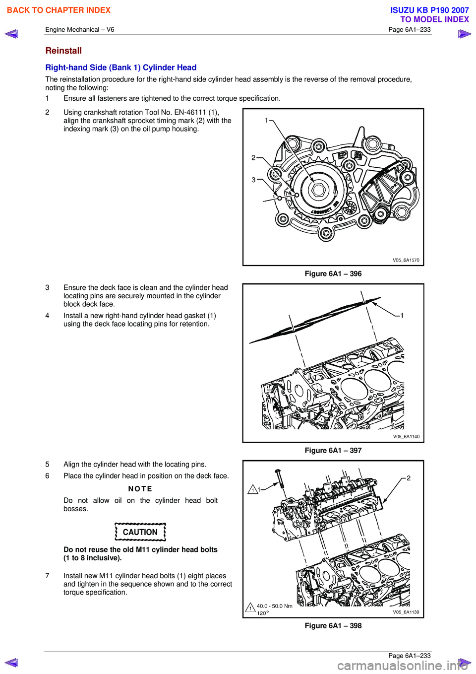
Reinstall
Right-hand Side (Bank 1) Cylinder Head
The reinstallation procedure for the right-hand side cylinder head assembly is the reverse of the removal procedure,
noting the following:
1 Ensure all fasteners are tightened to the correct torque specification.
2 Using crankshaft rotation Tool No. EN-46111 (1), align the crankshaft sprocket timing mark (2) with the
indexing mark (3) on the oil pump housing.
Figure 6A1 – 396
3 Ensure the deck face is clean and the cylinder head locating pins are securely mounted in the cylinder
block deck face.
4 Install a new right-hand cylinder head gasket (1) using the deck face locating pins for retention.
Figure 6A1 – 397
5 Align the cylinder head with the locating pins.
6 Place the cylinder head in position on the deck face.
NOTE
Do not allow oil on the cylinder head bolt
bosses.
CAUTION
Do not reuse the old M11 cylinder head bolts
(1 to 8 inclusive).
7 Install new M11 cylinder head bolts (1) eight places and tighten in the sequence shown and to the correct
torque specification.
Figure 6A1 – 398
BACK TO CHAPTER INDEX
TO MODEL INDEX
ISUZU KB P190 2007
Page 3011 of 6020
Engine Mechanical – V6 Page 6A1–234
Page 6A1–234
�„ Cylinder head M11 attaching bolt
torque specification:
Stage 1:............. 40.0 – 50.0 Nm
Stage 2:.............................. 120°
Figure 6A1 – 399
Left-hand Side (Bank 2) Cylinder Head
The reinstallation procedure for the left-hand side cylinder head a ssembly is the reverse of the removal procedure, noting
the following:
1 Ensure all fasteners are tightened to the correct torque specification.
2 Using crankshaft rotation Tool No. EN-46111 (1), align the crankshaft sprocket timing mark (2) with the
indexing mark (3) on the oil pump housing.
Figure 6A1 – 400
3 Ensure the deck face is clean and the cylinder head locating pins are securely mounted in the cylinder
block deck face.
4 Install a new cylinder head gasket (1) using the deck face locating pins for retention.
Figure 6A1 – 401
BACK TO CHAPTER INDEX
TO MODEL INDEX
ISUZU KB P190 2007
Page 3059 of 6020
Engine Mechanical – V6 Page 6A1–282
Page 6A1–282
4 Loosen the nuts (1) of the crankshaft main bearing
cap remover, Tool No. J-41818 (2) to separate the
chamfered collets. Install the collets into the inner bolt
holes of the front main bearing cap (3).
5 Tighten the remover nuts to the correct torque specification.
Crankshaft bearing cap remover nut.................11.0 Nm.
6 Install a slide hammer, Tool No. J-6125-1B (4) onto the crankshaft bearing cap remover and remove the
crankshaft bearing cap.
7 Repeat steps 9 to 14 for the remaining crankshaft bearing caps.
Figure 6A1 – 501
8 Remove the crankshaft (1) from the engine block (2), lifting evenly to avoid jamming against the main thrust
bearing.
9 Place the crankshaft in a secure place.
Figure 6A1 – 502
10 If required, remove the crankshaft sprocket drive pin (1) from the crankshaft (2),
Figure 6A1 – 503
BACK TO CHAPTER INDEX
TO MODEL INDEX
ISUZU KB P190 2007
Page 3160 of 6020
Engine Cooling – V6 Engine Page 6B1–25
3.4 Cleaning Cooling System
NOTE
• Before carrying out reverse flushing
procedures, it is recommended that a
cleaning solution be used to loosen scale and
corrosion. Only use a Holden approved
radiator cleaner following the instructions on
the container label.
• This operation should only be carried out
when the engine and radiator are at ambient
temperature.
• When using specialised cooling system
flushing equipment, connect the equipment as
recommended by the manufacturer.
Cooling System Reverse Flush
Radiator
Refer to ‘
‘‘
‘
Environmental Issues ’
’’
’
in 3.1
Service Notes, before draining the coolant.
1 Drain the cooling system. Refer to 3.3 Draining and Filling Cooling System in this Section.
Always wear eye protection when working
with spring-type hose clamps. Failure to do
so may result in eye injury.
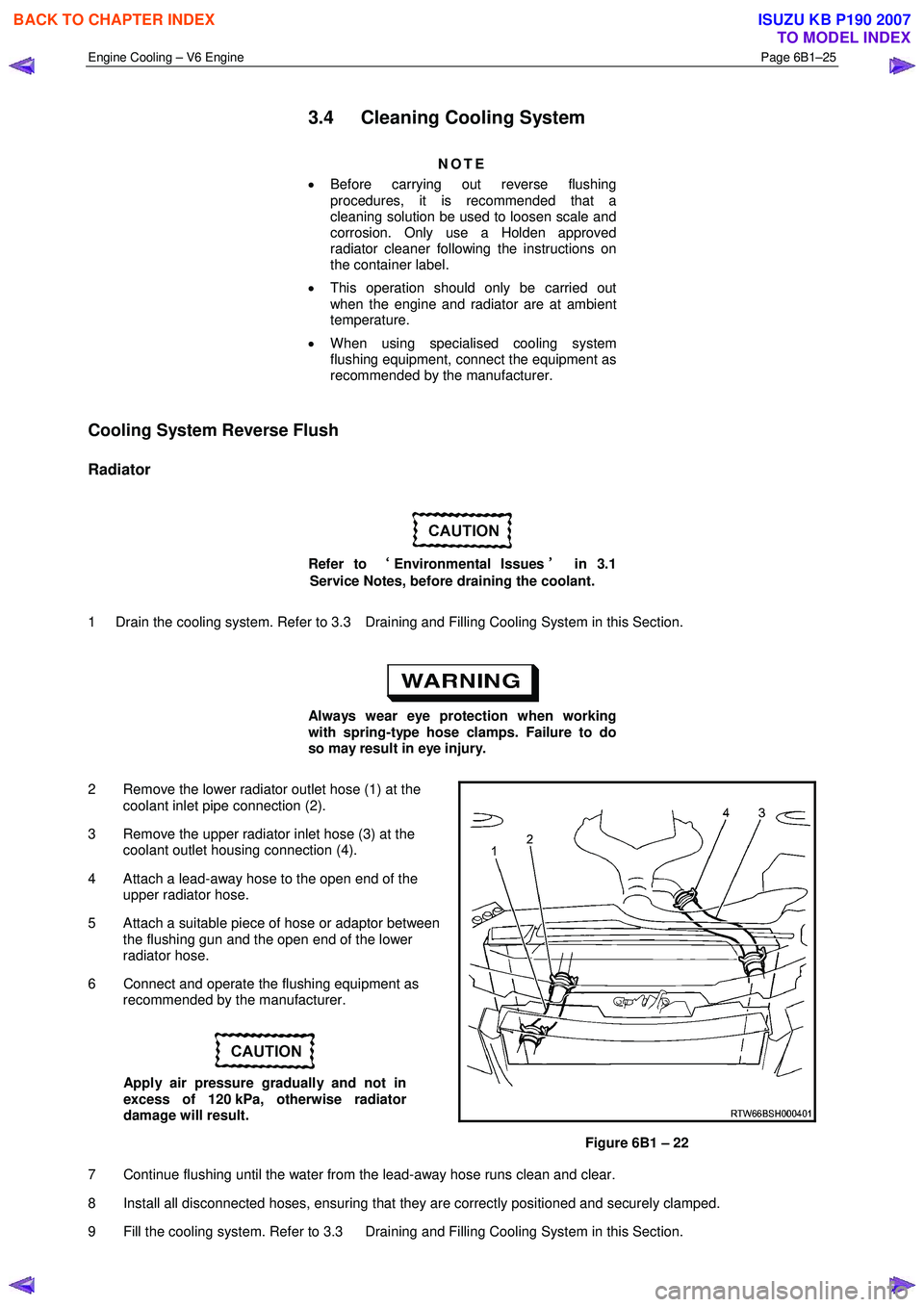
2 Remove the lower radiator outlet hose (1) at the coolant inlet pipe connection (2).
3 Remove the upper radiator inlet hose (3) at the coolant outlet housing connection (4).
4 Attach a lead-away hose to the open end of the upper radiator hose.
5 Attach a suitable piece of hose or adaptor between the flushing gun and the open end of the lower
radiator hose.
6 Connect and operate the flushing equipment as recommended by the manufacturer.
Apply air pressure gradually and not in
excess of 120 kPa, otherwise radiator
damage will result.
Figure 6B1 – 22
7 Continue flushing until the water from the lead-away hose runs clean and clear.
8 Install all disconnected hoses, ensuring that they are correctly positioned and securely clamped.
9 Fill the cooling system. Refer to 3.3 Draining and Filling Cooling System in this Section.
BACK TO CHAPTER INDEX
TO MODEL INDEX
ISUZU KB P190 2007
Page 3161 of 6020
Engine Cooling – V6 Engine Page 6B1–26
10 Pressure test the cooling system. Refer to 3.7 Pressure Testing in this Section.
Engine
Refer to ‘
‘‘
‘
Environmental Issues ’
’’
’
in 3.1
Service Notes, before draining the coolant.
1 Drain the cooling system. Refer to 3.3 Draining and Filling Cooling System in this Section.
Always wear eye protection when working
with spring-type hose clamps. Failure to do
so may result in eye injury.
2 Remove the upper and lower radiator hoses from the coolant outlet housing and coolant inlet pipe connections. Refer to Figure 6B1 – 22.
3 Remove the thermostat housing from the rear of the engine block. Refer to 6A1 Engine Mechanical – V6..
4 Remove the thermostat from the thermostat housing and reinstall the housing to the rear of the intake manifold. Refer to 3.8 Thermostat in this Section.
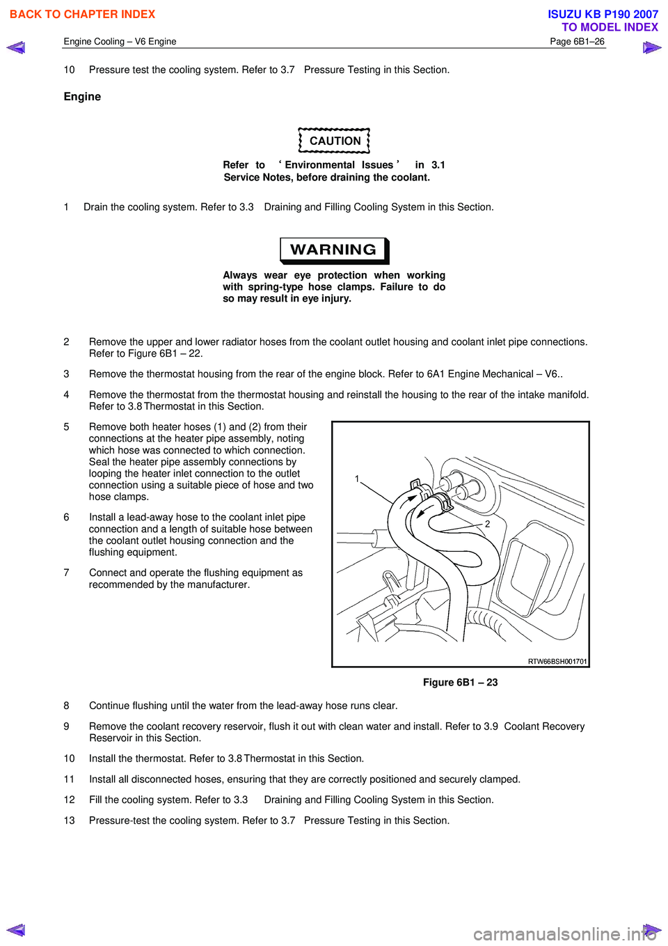
5 Remove both heater hoses (1) and (2) from their connections at the heater pipe assembly, noting
which hose was connected to which connection.
Seal the heater pipe assembly connections by
looping the heater inlet connection to the outlet
connection using a suitable piece of hose and two
hose clamps.
6 Install a lead-away hose to the coolant inlet pipe connection and a length of suitable hose between
the coolant outlet housing connection and the
flushing equipment.
7 Connect and operate the flushing equipment as recommended by the manufacturer.
Figure 6B1 – 23
8 Continue flushing until the water from the lead-away hose runs clear.
9 Remove the coolant recovery reservoir, flush it out with clean water and install. Refer to 3.9 Coolant Recovery Reservoir in this Section.
10 Install the thermostat. Refer to 3.8 Thermostat in this Section.
11 Install all disconnected hoses, ensuring that they are correctly positioned and securely clamped.
12 Fill the cooling system. Refer to 3.3 Draining and Filling Cooling System in this Section.
13 Pressure-test the cooling system. Refer to 3.7 Pressure Testing in this Section.
BACK TO CHAPTER INDEX
TO MODEL INDEX
ISUZU KB P190 2007