2007 ISUZU KB P190 ECU
[x] Cancel search: ECUPage 3719 of 6020
Powertrain Interface Module – V6 Page 6E1–58
• For intermittent fault conditions, refer to Intermittent Fault Conditions.
• Since fault conditions in a wiring connector may trigger DTCs, always test the connectors related to this diagnostic
procedure for shorted terminals or poor wiring connection before replacing any component. Refer to 8A Electrical -
Body and Chassis for information on electrical fault diagnosis.
Conditions for Running the DTC
Conditions for running the DTC are:
• The ignition is switched on.
• The ignition voltage is 10.0 – 16.0 V.
Conditions for Setting the DTC
An incorrect security code is entered into Tech 2 when attempting to program the PIM.
Action Taken When the DTC Sets
W hen the DTC sets, the following action is taken:
• The vehicle will not start whilst the PIM is in a lock-out state.
NOTE
When the DTC sets, there is no warning lamp
displayed on the instrument cluster.
Conditions for Clearing the DTC
Refer to 4.1 Diagnostic General Descriptions for information on the conditions for clearing DTCs.
Test Description
The following number refers to the step numbers in the diagnostic table:
4 This step tests the PIM ground circuits and supply voltage.
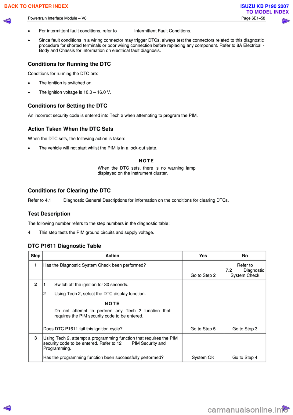
DTC P1611 Diagnostic Table
Step Action Yes No
1
Has the Diagnostic System Check been performed?
Go to Step 2 Refer to
7.2 Diagnostic System Check
2 1 Switch off the ignition for 30 seconds.
2 Using Tech 2, select the DTC display function.
NOTE
Do not attempt to perform any Tech 2 function that
requires the PIM security code to be entered.
Does DTC P1611 fail this ignition cycle? Go to Step 5 Go to Step 3
3 Using Tech 2, attempt a programming function that requires the PIM
security code to be entered. Refer to 12 PIM Security and
Programming.
Has the programming function been successfully performed? System OK Go to Step 4
BACK TO CHAPTER INDEX
TO MODEL INDEX
ISUZU KB P190 2007
Page 3732 of 6020
Powertrain Interface Module – V6 Page 6E1–71
11 Service Operations
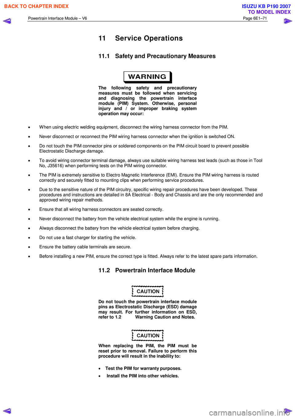
11.1 Safety and Precautionary Measures
The following safety and precautionary
measures must be followed when servicing
and diagnosing the powertrain interface
module (PIM) System. Otherwise, personal
injury and / or improper braking system
operation may occur:
• W hen using electric welding equipment, disconnect the wiring harness connector from the PIM.
• Never disconnect or reconnect the PIM wiring harness connector when the ignition is switched ON.
• Do not touch the PIM connector pins or soldered components on the PIM circuit board to prevent possible
Electrostatic Discharge damage.
• To avoid wiring connector terminal damage, always use suitable wiring harness test leads (such as those in Tool
No, J35616) when performing tests on the PIM wiring connector.
• The PIM is extremely sensitive to Electro Magnetic Interference (EMI). Ensure the PIM wiring harness is routed
correctly and securely fitted to mounting clips when performing service procedures.
• Due to the sensitive nature of the PIM circuitry, specific wiring repair procedures have been developed. These
procedures and instructions are detailed in 8A Electrical - Body and Chassis and are the only recommended and
approved wiring repair methods.
• Ensure that all wiring harness connectors are seated correctly.
• Never disconnect the battery from the vehicle electrical system while the engine is running.
• Always disconnect the battery from the vehicle electrical system before charging.
• Do not use a fast charger for starting the vehicle.
• Ensure the battery cable terminals are secure.
• Before installing a new PIM, ensure the correct type is fitted. Always refer to the latest spare parts information.
11.2 Powertrain Interface Module
Do not touch the powertrain interface module
pins as Electrostatic Discharge (ESD) damage
may result. For further information on ESD,
refer to 1.2 Warning Caution and Notes.
When replacing the PIM, the PIM must be
reset prior to removal. Failure to perform this
procedure will result in the inability to:
• Test the PIM for warranty purposes.
• Install the PIM into other vehicles.
BACK TO CHAPTER INDEX
TO MODEL INDEX
ISUZU KB P190 2007
Page 3734 of 6020
Powertrain Interface Module – V6 Page 6E1–73
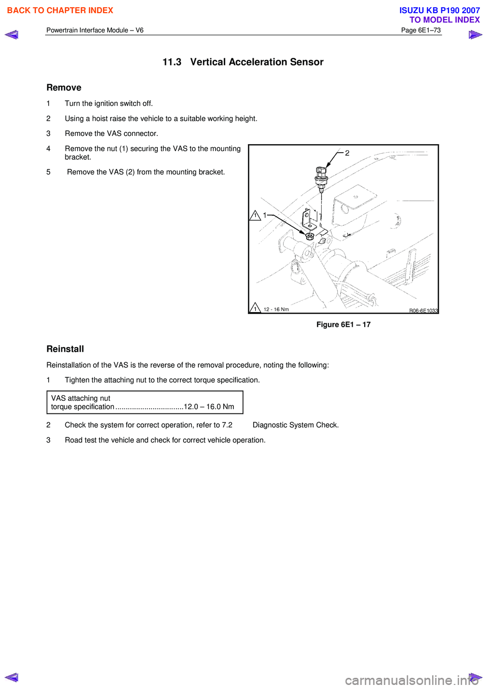
11.3 Vertical Acceleration Sensor
Remove
1 Turn the ignition switch off.
2 Using a hoist raise the vehicle to a suitable working height.
3 Remove the VAS connector.
4 Remove the nut (1) securing the VAS to the mounting bracket.
5 Remove the VAS (2) from the mounting bracket.
Figure 6E1 – 17
Reinstall
Reinstallation of the VAS is the reverse of the removal procedure, noting the following:
1 Tighten the attaching nut to the correct torque specification.
VAS attaching nut
torque specification .................................12.0 – 16.0 Nm
2 Check the system for correct operation, refer to 7.2 Diagnostic System Check.
3 Road test the vehicle and check for correct vehicle operation.
BACK TO CHAPTER INDEX
TO MODEL INDEX
ISUZU KB P190 2007
Page 3735 of 6020
Powertrain Interface Module – V6 Page 6E1–74
12 PIM Security and Programming
12.1 Security and Programming Information
Car Pass Card
W hen performing certain powertrain interface module (PIM) programming functions using Tech 2, you may be prompted
to enter a four digit Security Code (1). This information is found on the car pass card issued with the vehicle when new. If
the card is unavailable, contact the GM Holden Technical Assistance (TAS) centre to obtain the relevant Security Code.
Security Code
The security code is required when performing certain PIM, ICU and ECM programming functions. W hen Tech 2
requests the security code to be entered, and an incorrect code is entered, the PIM will go into a security wait time stage.
This wait time stage will prevent any further attempts to enter the security code until the wait time has elapsed.
Should a second incorrect security code be entered after the initial wait time has elapsed, the PIM will go into a second
wait time stage. The wait time will increase each time an incorrect code is entered. W hen the correct code is entered the
wait time will reset back to its original value of 10 seconds.
NOTE
The ignition switch must be in the ON position
with the battery connected during the wait time
period.
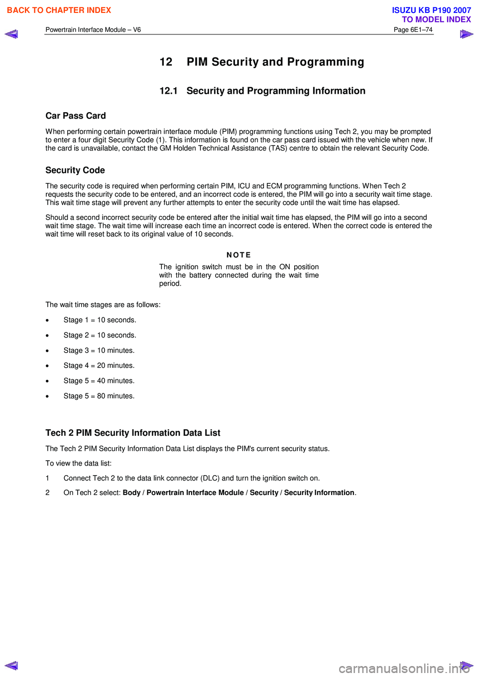
The wait time stages are as follows:
• Stage 1 = 10 seconds.
• Stage 2 = 10 seconds.
• Stage 3 = 10 minutes.
• Stage 4 = 20 minutes.
• Stage 5 = 40 minutes.
• Stage 5 = 80 minutes.
Tech 2 PIM Security Information Data List
The Tech 2 PIM Security Information Data List displays the PIM's current security status.
To view the data list:
1 Connect Tech 2 to the data link connector (DLC) and turn the ignition switch on.
2 On Tech 2 select: Body / Powertrain Interface Module / Security / Security Information .
BACK TO CHAPTER INDEX
TO MODEL INDEX
ISUZU KB P190 2007
Page 3736 of 6020
Powertrain Interface Module – V6 Page 6E1–75
NOTE
The Tech 2 PIM Security Information Data List
typical display values are obtained from a
correctly operating vehicle under the following
conditions:
• ignition switched on,
• engine not running, and
• vehicle is stationary.
Tech 2 Parameter Units Displayed Typical Display Values
ICU / PIM Status Yes / No Yes
Security Code Programmed Yes / No Yes
Security W ait Time Inactive / Active Inactive
Security W ait Time Inactive / 0:00:00 Inactive
Security Code Correct Enter Yes / No Yes
Security Code Reset Counter 0 0
12.2 PIM Reset Procedure
Do not perform the reset procedure within
sixty seconds of turning the ignition switch
on. Failure to comply may result in the PIM
failing to reset.
W hen a PIM has been installed into a vehicle, it is security linked to the immobiliser control unit (ICU) and engine control
module (ECM). Once this linking has been performed, the PIM cannot be installed in any other vehicle, unless the
security linking between the ICU and the ECM has been reset using the following procedure:
1 Prior to resetting the PIM, obtain the Security Code. For further information, refer to 12.1 Security and Programming Information.
2 Connect Tech 2 to the data link connector (DLC) and turn the ignition switch on.
3 On Tech 2 select: Body / Powertrain Interface Module / Security / Reset PIM .
NOTE
When Tech 2 requests programming approval,
obtain TIS approval.
NOTE
If a Tech 2 screen displaying Security Wait Time
Active, Please Wait! appears after selecting the
Reset PIM option, an incorrect security code has
been previously entered. Refer to 12.1
Security and Programming Information for further
information.
4 W hen Tech 2 displays Enter Security Code, enter the security code, press the Enter key and then the Okay soft
key.
The engine will not start after the PIM has
been reset.
5 W hen Tech 2 displays Do you really want to Reset? , press the Reset soft key.
BACK TO CHAPTER INDEX
TO MODEL INDEX
ISUZU KB P190 2007
Page 3737 of 6020
Powertrain Interface Module – V6 Page 6E1–76
Do not turn the ignition switch off within 60
seconds of performing the PIM reset
procedure. Failure to comply may result in the
PIM failing to reset.
6 W hen Tech 2 displays Reset Completed Successfully , press the Confirm soft key to return to the Tech 2
Security screen.
12.3 PIM Configuration
Configuring the PIM
Programming Transmission Variant
1 Connect Tech 2 to the data link connector (DLC).
2 On Tech 2 select: Body / Powertrain Interface Module / Program / Program Variant Configuration.
3 Press the Modify soft key.
4 Using the up or down arrow selection keys, select either manual or automatic transmission.
5 Press the Confirm soft key. Tech 2 reverts to the main Tech 2 Program Variant Configuration screen where the
selection made in the previous step is displayed.
6 Press the Program soft key. The changes are now programmed into the PIM.
Do not turn the ignition switch off within 60
seconds of configuring the PIM. Failure to
comply may result in the changes failing to be
programmed into the PIM.
7 W hen notified that the programming was successful, press the Confirm soft key to return to the Tech 2 Program
screen.
Programming the VIN
1 Connect Tech 2 to the data link connector (DLC).
2 On Tech 2 select: Body / Powertrain Interface Module / Program / Program VIN .
3 Enter the VIN using the Tech 2 arrow selection keys.
NOTE
The left and right arrow selection keys move the
Tech 2 cursor along the VIN number, whilst the
up and down selection arrows change the
character value.
Numbers can also be entered by pressing the
number key's on Tech 2.
4 After entering the VIN number, press the Enter key. The changes are now programmed into the PIM.
BACK TO CHAPTER INDEX
TO MODEL INDEX
ISUZU KB P190 2007
Page 3738 of 6020
Powertrain Interface Module – V6 Page 6E1–77
Do not turn the ignition switch off within 60
seconds of programming the VIN. Failure to
comply may result in the changes failing to be
programmed into the PIM.
5 W hen notified that the programming was successful, press the Confirm soft key to return to the Tech 2 Program
screen.
12.4 Immobiliser Link to ECM / PIM
Do not perform the Immobiliser Link to ECM /
PIM procedure within sixty seconds of turning
the ignition switch on. Failure to comply may
result in the PIM failing to link.
W hen the powertrain interface module (PIM) has been replaced, it is necessary to security link the PIM to the immobiliser
control unit (ICU) and engine control module (ECM) before the vehicle will start.
NOTE
This linking procedure between the ECM and PIM
is also known as the Immobiliser Function
Programming.
1 Prior to performing the linking procedure, obtain the security code. For further information, refer to 12.1Security and Programming Information.
2 Connect Tech 2 to the data link connector (DLC).
3 On Tech 2 select: Body / Powertrain Interface Module / Security / Immobiliser Link to ECM / PIM .
4 W hen Tech 2 displays Immobiliser Replaced, press the No soft key.
5 W hen Tech 2 displays PIM or ECM Replaced?, press the Yes soft key.
NOTE
When Tech 2 requests programming approval,
obtain TIS approval.
6 W hen Tech 2 displays Enter Security Code, enter the security code and press the Enter key and then the Okay
soft key.
7 W hen Tech 2 displays Confirm Security Code, re-enter the security code, press the Enter key and then the Okay
soft key.
8 W hen Tech 2 displays Select Immobiliser Programming Routine , use the up or down arrow selection keys, to
select the PIM Replaced option and press the Enter key.
9 W hen Tech 2 displays Stop Engine – Turn Off Ignition , turn the ignition switch off and press the Confirm soft key.
10 W hen Tech 2 displays Turn Ignition On, turn the ignition switch on and press the Confirm soft key.
BACK TO CHAPTER INDEX
TO MODEL INDEX
ISUZU KB P190 2007
Page 3739 of 6020

Powertrain Interface Module – V6 Page 6E1–78
Do not turn the ignition switch off within 60
seconds of performing the ICU Link to
ECM / PIM procedure. Failure to comply may
result in the PIM failing to link with the
ICU / ECM.
11 W hen Tech 2 displays Programming Successful, press the Confirm soft key to return to the Tech 2 Security
screen.
BACK TO CHAPTER INDEX
TO MODEL INDEX
ISUZU KB P190 2007