2007 ISUZU KB P190 ECU
[x] Cancel search: ECUPage 3524 of 6020

Engine Management – V6 – Diagnostics Page 6C1-2–246
NOTE
After an ECU reset, the ignition switch must be
turned Off for at least 10 seconds and then
turned On for at least one minute, before
attempting communication between Tech 2 and
the ECU.
Preconditions: The four digit security code must be entered into Tech 2 and the theft deterrent system
must be disarmed and the ignition switched ‘On’ with a programmed remote coded key.
F2: Fuel Trim Reset : This function resets the fuel trim data values learned by the ECM.
F3: Throttle Body Relearn : In this mode, Tech 2 commands the throttle plate from its rest position to full closed
then to about 10% open. This procedure takes approximately 6 – 8 seconds. At the start of this procedure,
the Tech 2, ‘Electronic Throttle Control Learn Counter’ parameter should display ‘0’ then count up to 11, after
the procedure is completed. If the counter does not start at ‘0’, nor display a count of ‘11’ at the conclusion of
the procedure, a fault has occurred and a DTC will set.
BACK TO CHAPTER INDEX
TO MODEL INDEX
ISUZU KB P190 2007
Page 3528 of 6020
Engine Management – V6 – Service Operations Page 6C1-3–4
1 General Information
1.1 General Description
This Section describes the correct service procedures to repair and test components of the V6 engine management
system. Emphasis is placed on the proper procedures and repair of components related to this specific system.
For component description, operation and location, refer to 6C1-1 Engine Management – V6 – General Information.
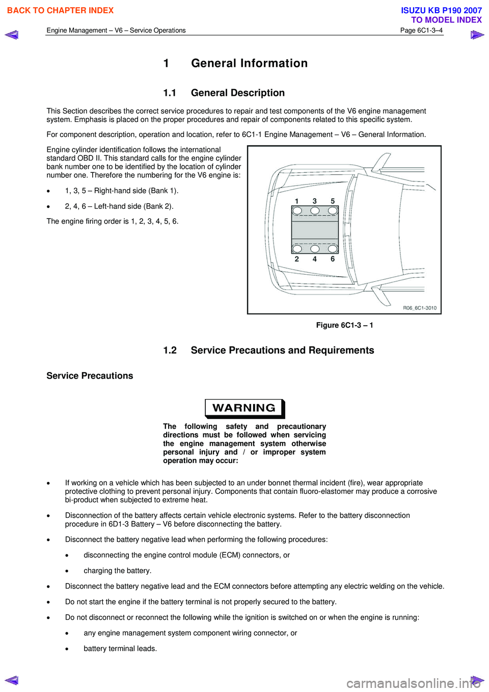
Engine cylinder identification follows the international
standard OBD II. This standard calls for the engine cylinder
bank number one to be identified by the location of cylinder
number one. Therefore the numbering for the V6 engine is:
• 1, 3, 5 – Right-hand side (Bank 1).
• 2, 4, 6 – Left-hand side (Bank 2).
The engine firing order is 1, 2, 3, 4, 5, 6.
Figure 6C1-3 – 1
1.2 Service Precautions and Requirements
Service Precautions
The following safety and precautionary
directions must be followed when servicing
the engine management system otherwise
personal injury and / or improper system
operation may occur:
• If working on a vehicle which has been subjected to an under bonnet thermal incident (fire), wear appropriate
protective clothing to prevent personal injury. Components that contain fluoro-elastomer may produce a corrosive
bi-product when subjected to extreme heat.
• Disconnection of the battery affects certain vehicle electronic systems. Refer to the battery disconnection
procedure in 6D1-3 Battery – V6 before disconnecting the battery.
• Disconnect the battery negative lead when performing the following procedures:
• disconnecting the engine control module (ECM) connectors, or
• charging the battery.
• Disconnect the battery negative lead and the ECM connectors before attempting any electric welding on the vehicle.
• Do not start the engine if the battery terminal is not properly secured to the battery.
• Do not disconnect or reconnect the following while the ignition is switched on or when the engine is running:
• any engine management system component wiring connector, or
• battery terminal leads.
BACK TO CHAPTER INDEX
TO MODEL INDEX
ISUZU KB P190 2007
Page 3544 of 6020
Engine Management – V6 – Service Operations Page 6C1-3–20
Reinstall
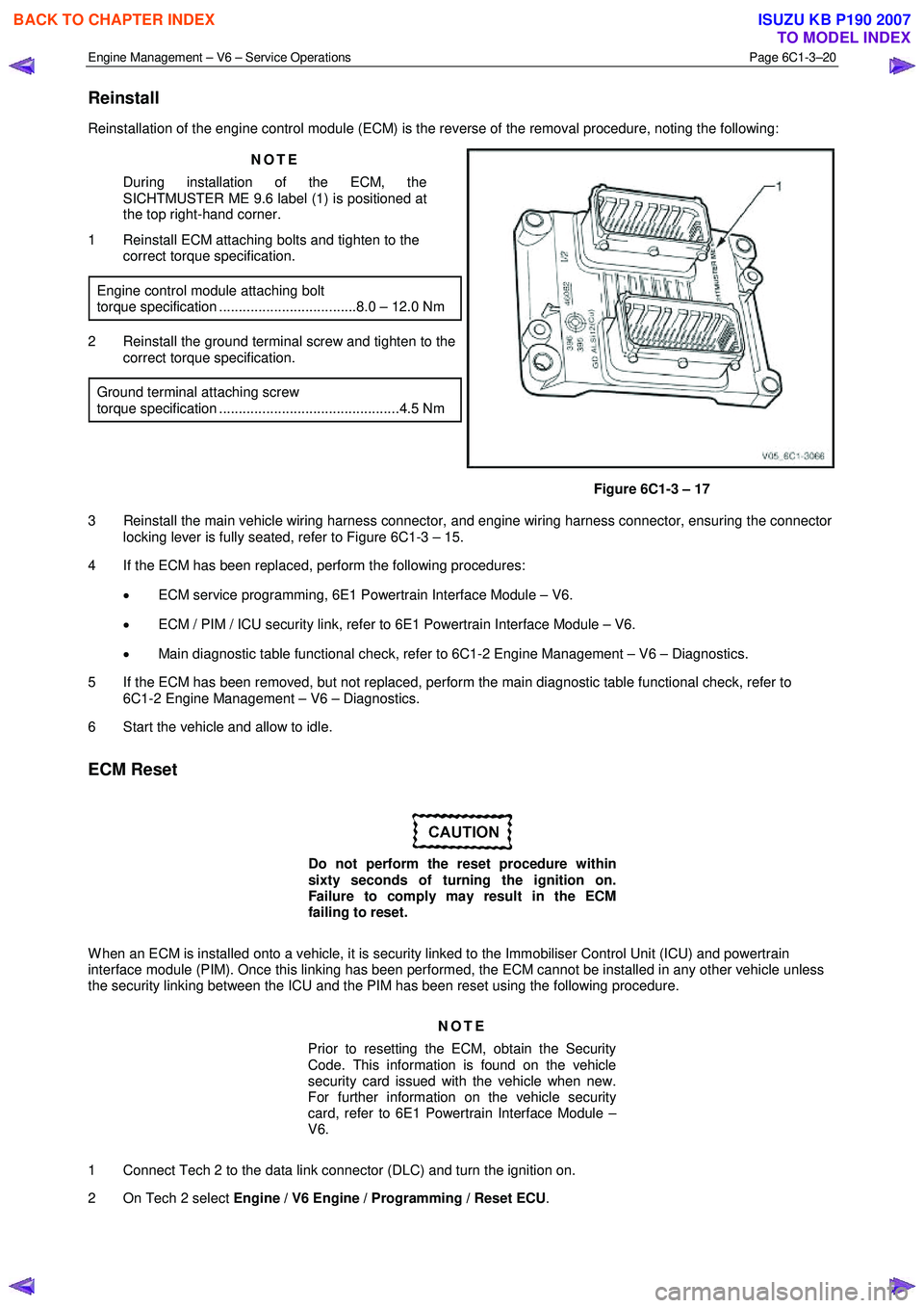
Reinstallation of the engine control module (ECM) is the reverse of the removal procedure, noting the following:
NOTE
During installation of the ECM, the
SICHTMUSTER ME 9.6 label (1) is positioned at
the top right-hand corner.
1 Reinstall ECM attaching bolts and tighten to the correct torque specification.
Engine control module attaching bolt
torque specification ...................................8.0 – 12.0 Nm
2 Reinstall the ground terminal screw and tighten to the correct torque specification.
Ground terminal attaching screw
torque specification ..............................................4.5 Nm
Figure 6C1-3 – 17
3 Reinstall the main vehicle wiring harness connector, and engine wiring harness connector, ensuring the connector locking lever is fully seated, refer to Figure 6C1-3 – 15.
4 If the ECM has been replaced, perform the following procedures:
• ECM service programming, 6E1 Powertrain Interface Module – V6.
• ECM / PIM / ICU security link, refer to 6E1 Powertrain Interface Module – V6.
• Main diagnostic table functional check, refer to 6C1-2 Engine Management – V6 – Diagnostics.
5 If the ECM has been removed, but not replaced, perform the main diagnostic table functional check, refer to 6C1-2 Engine Management – V6 – Diagnostics.
6 Start the vehicle and allow to idle.
ECM Reset
Do not perform the reset procedure within
sixty seconds of turning the ignition on.
Failure to comply may result in the ECM
failing to reset.
W hen an ECM is installed onto a vehicle, it is security linked to the Immobiliser Control Unit (ICU) and powertrain
interface module (PIM). Once this linking has been performed, the ECM cannot be installed in any other vehicle unless
the security linking between the ICU and the PIM has been reset using the following procedure.
NOTE
Prior to resetting the ECM, obtain the Security
Code. This information is found on the vehicle
security card issued with the vehicle when new.
For further information on the vehicle security
card, refer to 6E1 Powertrain Interface Module –
V6.
1 Connect Tech 2 to the data link connector (DLC) and turn the ignition on.
2 On Tech 2 select Engine / V6 Engine / Programming / Reset ECU .
BACK TO CHAPTER INDEX
TO MODEL INDEX
ISUZU KB P190 2007
Page 3545 of 6020
Engine Management – V6 – Service Operations Page 6C1-3–21
NOTE
When Tech 2 requests programming approval,
obtain TIS approval.
3 W hen Tech 2 displays Enter Security Code, enter the security code, press the Enter key and then the Okay soft
key.
The engine will not start after the ECM has
been reset.
4 W hen Tech 2 displays Do you really want to Reset? , press the Reset soft key.
5 W hen Tech 2 displays Stop Engine - Turn Off Ignition , turn the ignition off and press the Confirm soft key.
6 W hen Tech 2 displays Turn Ignition On, turn the ignition on and press the Confirm soft key.
7 W hen Tech 2 displays Reset Completed Successfully , press the Confirm soft key to return to the Tech 2
Programming screen.
2.8 Engine Control Module Bracket Assembly
Remove
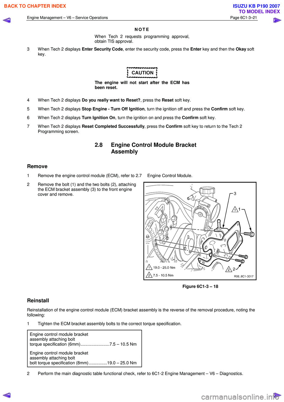
1 Remove the engine control module (ECM), refer to 2.7 Engine Control Module.
2 Remove the bolt (1) and the two bolts (2), attaching the ECM bracket assembly (3) to the front engine
cover and remove.
Figure 6C1-3 – 18
Reinstall
Reinstallation of the engine control module (ECM) bracket assembly is the reverse of the removal procedure, noting the
following:
1 Tighten the ECM bracket assembly bolts to the correct torque specification.
Engine control module bracket
assembly attaching bolt
torque specification (6mm)........................7.5 – 10.5 Nm
Engine control module bracket
assembly attaching bolt
bolt torque specification (8mm) ...............19.0 – 25.0 Nm
2 Perform the main diagnostic table functional check, refer to 6C1-2 Engine Management – V6 – Diagnostics.
BACK TO CHAPTER INDEX
TO MODEL INDEX
ISUZU KB P190 2007
Page 3559 of 6020
Engine Management – V6 – Service Operations Page 6C1-3–35
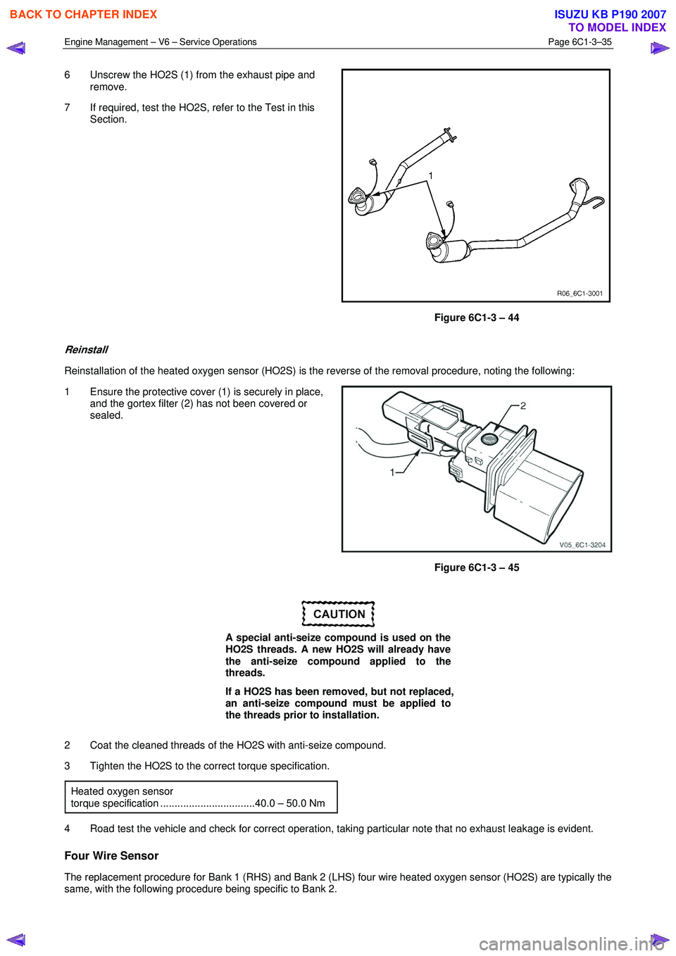
6 Unscrew the HO2S (1) from the exhaust pipe and
remove.
7 If required, test the HO2S, refer to the Test in this Section.
Figure 6C1-3 – 44
Reinstall
Reinstallation of the heated oxygen sensor (HO2S) is the reverse of the removal procedure, noting the following:
1 Ensure the protective cover (1) is securely in place, and the gortex filter (2) has not been covered or
sealed.
Figure 6C1-3 – 45
A special anti-seize compound is used on the
HO2S threads. A new HO2S will already have
the anti-seize compound applied to the
threads.
If a HO2S has been removed, but not replaced,
an anti-seize compound must be applied to
the threads prior to installation.
2 Coat the cleaned threads of the HO2S with anti-seize compound.
3 Tighten the HO2S to the correct torque specification.
Heated oxygen sensor
torque specification .................................40.0 – 50.0 Nm
4 Road test the vehicle and check for correct operation, taking particular note that no exhaust leakage is evident.
Four Wire Sensor
The replacement procedure for Bank 1 (RHS) and Bank 2 (LHS) four wire heated oxygen sensor (HO2S) are typically the
same, with the following procedure being specific to Bank 2.
BACK TO CHAPTER INDEX
TO MODEL INDEX
ISUZU KB P190 2007
Page 3580 of 6020
Engine Management – V6 – Service Operations Page 6C1-3–56
3 Reinstall the throttle body bolts and tighten to the correct torque specification.
Throttle body assembly attaching bolt
torque specification ...................................8.0 – 12.0 Nm
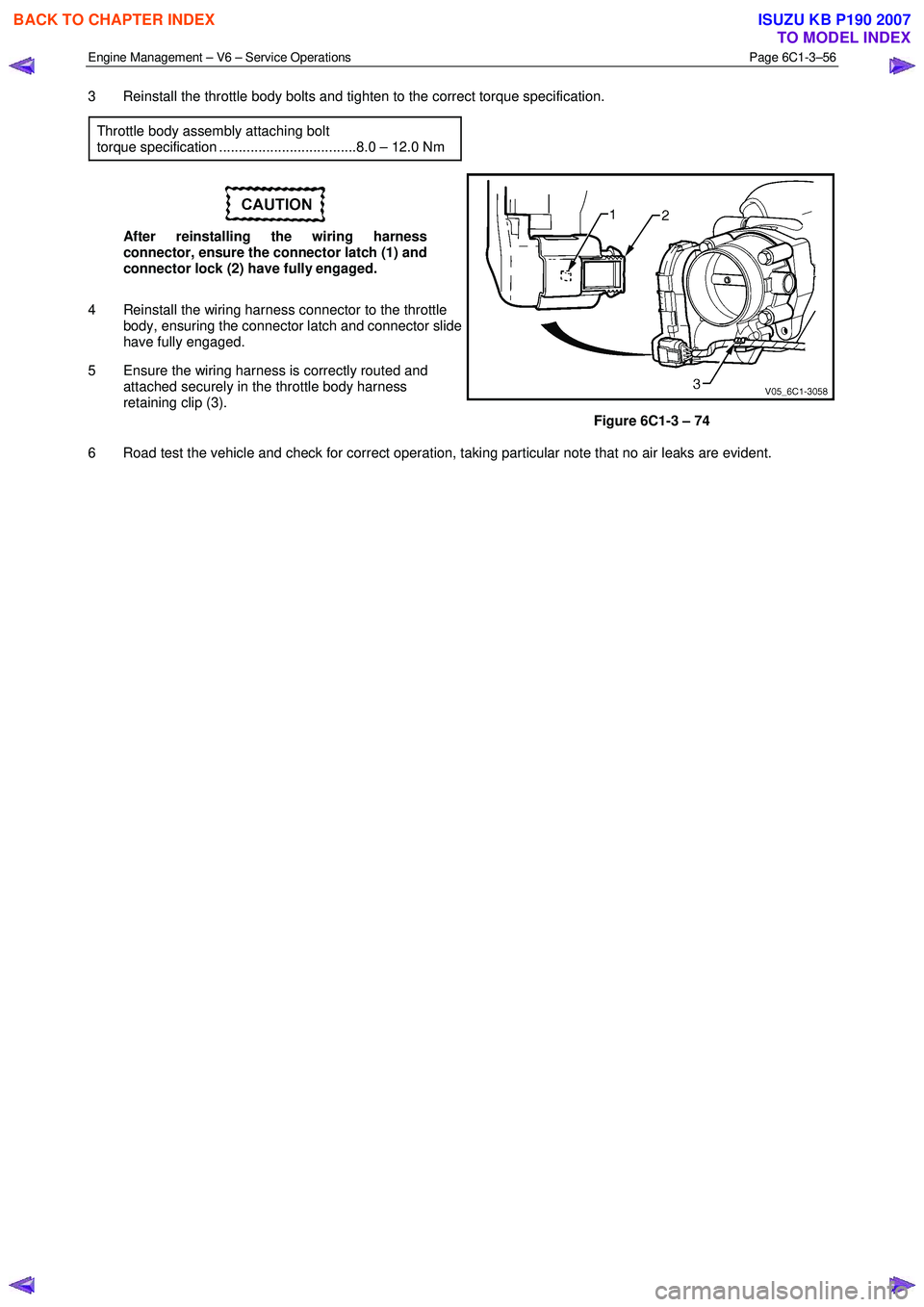
After reinstalling the wiring harness
connector, ensure the connector latch (1) and
connector lock (2) have fully engaged.
4 Reinstall the wiring harness connector to the throttle body, ensuring the connector latch and connector slide
have fully engaged.
5 Ensure the wiring harness is correctly routed and attached securely in the throttle body harness
retaining clip (3).
Figure 6C1-3 – 74
6 Road test the vehicle and check for correct operation, taking particular note that no air leaks are evident.
BACK TO CHAPTER INDEX
TO MODEL INDEX
ISUZU KB P190 2007
Page 3615 of 6020
Starting System – V6 Page 6D1-2–7
2 Diagnostics
2.1 Diagnostic General Information
NOTE
There is a minimum battery voltage threshold
value. If the battery voltage is below the set value,
the ECU will inhibit cranking. Refer to 6C1-1
Engine Management – V6 – General Information
for further information.
Basic Diagnostic Tools Required
Use of incorrect electrical circuit diagnostic
tools when performing the cruise control
diagnostic procedures could result in
incorrect diagnostic results or damage to
components.
The following electrical circuit testing tools are required to perform the diagnostic procedures detailed in this Section:
• digital multimeter with 10 meg ohms impedance, and
• connector test adapter kit Tool No. KM609.
For further information on the use of these tools, refer to 8A Electrical Body and Chassis.
2.2 Tech 2 Data List
The Tech 2 displays the status of certain starting system parameters.
To view the data list:
1 Connect Tech 2 to the DLC.
2 On Tech 2 select: Engine / V6 Engine / Data Display / Data List / Electrical / Theft Data .
Tech 2 Parameter Units Displayed Typical Display Values
Crank Request Inactive / Active Inactive
Starter Relay Off / On Off
2.3 Diagnostic Systems Check
Step Action Yes No
1
Is the fault specifically isolated to this system / module?
Go to Step 2 Go to 0D Vehicle
Diagnostics
2 1 Connect Tech 2 to the DLC.
2 Ignition ON, engine OFF.
3 On Tech 2 select:
Engine / V6 Engine / Diagnostic Trouble codes / Read
DTC’s.
Are there any set DTC’s? Go to the
appropriate DTC
table in 6C1-2 Engine
Management – V6 – Diagnostics. Refer to 2.5
Starting
System Inoperative / Malfunctioning
BACK TO CHAPTER INDEX
TO MODEL INDEX
ISUZU KB P190 2007
Page 3623 of 6020
Starting System – V6 Page 6D1-2–15
3 Minor Service Operations
3.1 Safety Precautions
Observe the following precautions. Failure to observe these precautions can result in serious damage to components.
• Refer to 1.1 W ARNING, CAUTION and NOTES in this Service Information before disconnecting the battery.
• Use the starter motor on a negative ground system only.
• W hen installing a battery, attach the positive (+) cable to the battery first. Then attach the negative cable.
• W hen using a slave battery for starting purposes, ensure that both batteries are connected in parallel, that is.
positive to positive terminals and negative to negative terminals.
• Only use jumper leads that have surge protection.
3.2 Maintenance
Regular Checks
Check the following at regular intervals:
• Starter motor terminals – for corrosion and loose connectors.
• W iring – for damaged insulation.
• Mounting bolts – for tightness.
• Battery terminals – for clean and secure connections.
3.3 On-Vehicle Testing
NOTE
The battery must be fully charged and in
serviceable condition before beginning these
tests, refer to 8A Electrical Body and Chassis.
BACK TO CHAPTER INDEX
TO MODEL INDEX
ISUZU KB P190 2007