2007 ISUZU KB P190 engine
[x] Cancel search: enginePage 3751 of 6020
Exhaust System – V6 Page 6F – 3
The Catalytic converter can be damaged or
rendered ineffective, if:
• operated outside the limits of the closed
loop mixture control system
• the engine burns excessive amount of oil
• the exhaust temperature at the converter
is too high (exceeds 840°C).
The catalytic material is very sensitive to the effects of a rich or lean fuel mixture, which may cause the temperature of
the converter to rise rapidly. The catalytic converter normally operates at approximately 600 °C.
The catalytic converter is also sensitive to the use of leaded petrol. Using leaded fuel can cause deposits to form in the
converter, which restrict exhaust flow and prevent the catalyst from working. This will result in an increase in exhaust
backpressure and converter temperature.
NOTE
The use of unleaded petrol results in black
tailpipe deposits rather than the grey colour that
some people may normally associate with an
acceptable combustion condition. This black
colour resulting from the use of unleaded fuel
does not necessarily indicate a state of poor
engine tune. For V6 engines, Refer to: 6C1 – 1
Engine Management General Information.
Euro 3 Emissions Standards
The Euro 3 emissions standard is a European standard which aims at setting vehicle emissions targets to encourage
vehicle manufacturers to reduce harmful vehicle emissions such as Carbon Monoxide (CO), Hydrocarbons (HC) and the
various oxides of Nitrogen (NOx).
This vehicle is fitted with a supplemental
restraint system (SRS). Refer to section 9A
Restraints, in order to determine whether you
are performing service on or near the SRS
components or the SRS wiring.
Always use the correct fastener in the proper
location. When you replace a fastener, use
ONLY the exact part number for that
application. Isuzu will identify those fasteners
that require a replacement after removal and
fasteners that require thread lockers or thread
sealant. Unless otherwise specified, do not
use supplemental coatings (Paints, greases
or corrosion inhibitors) on thread fasteners or
fastener joints. Generally such coatings
adversely effect the fastener torque and the
joint clamping force, and may damage the
fastener. When you install fasteners, use the
correct tightening sequence and torque
specifications.
BACK TO CHAPTER INDEX
TO MODEL INDEX
ISUZU KB P190 2007
Page 3753 of 6020
Exhaust System – V6 Page 6F – 5
Service Notes
1. Vehicles fitted with catalytic converters should not be operated with leaded petrol. Lead will contaminate
the ceramic monolith.
2. Do not drop the catalytic converter as it will damage the ceramic monolith.
3. Replace the catalytic converter if it is damaged.
4. Do not allow water, oil or fuel to enter the converter as the ceramic monolith will be contaminated.
5. Do not use engine and/or fuel additives unless approved by General Motors. Many additives contain phosphorous that will contaminate the ceramic monolith.
6. The vehicle must not be started by pushing or towing, as unburned fuel could reach the catalytic converter and destroy the ceramic monolith. Always use jumper leads to start a vehicle that has a flat or
defective battery.
7. W hen carrying out a compression test, for V6 engines use Tech 2 to ensure the output control Engine Compression Test is set to enable, refer to 6A1 Engine Mechanical. This prevents fuel injection and
ignition during engine cranking.
8. Do not drive the vehicle with the engine misfiring or with any of the spark plug leads disconnected, as the catalytic converter will overheat.
9. Do not coast downhill with the engine misfiring or with any of the spark plug leads disconnected.
10. The catalytic converter is serviceable as part of the front exhaust assembly only. Refer to the service operations in this section for details of front exhaust pipe assembly removal and reinstallation.
11. The exhaust flange gaskets must be replaced whenever a new exhaust pipe, muffler or catalytic converter is installed.
1.3 WARNING, CAUTION and NOTES
This Section contains various W ARNINGS, CAUTIONS and NOTE statements that you must observe carefully to reduce
the risk of death or injury during service, repair procedures or vehicle operation. Incorrect service or repair procedures
may damage the vehicle or cause operational faults. W ARNINGS, CAUTION and NOTE statements are not exhaustive.
HOLDEN LTD can not possibly warn of all the potentially hazardous consequences of failure to follow these instructions.
1.1 Definition of WARNING, CAUTION and NOTE Statements
Diagnosis and repair procedures in this Section contain both general and specific W ARNING, CAUTION and NOTE
statements. HOLDEN LTD is dedicated to the presentation of service information that helps the technician to diagnose
and repair the systems necessary for proper operation of the vehicle. Certain procedures may present a hazard to the
technician if they are not followed in the recommended manner. W ARNING, CAUTION and NOTE statements are
designed to help prevent these hazards from occurring, but not all hazards can be foreseen.
WARNING defined
A W ARNING statement immediately precedes an operating procedure or maintenance practice which, if not correctly
followed, could result in death or injury. A W ARNING statement alerts you to take necessary action or not to take a
prohibited action. If a W ARNING statement is ignored, the following consequences may occur:
• Death or injury to the technician or other personnel working on the vehicle,
• Death or injury to other people in or near the workplace area, and / or
• Death or injury to the driver / or passenger(s) of the vehicle or other people, if the vehicle has been improperly
repaired.
CAUTION defined
A CAUTION statement immediately precedes an operating procedure or maintenance practice which, if not correctly
followed, could result in damage to or destruction of equipment, or corruption of data. If a CAUTION statement is
ignored, the following consequences may occur:
• Damage to the vehicle,
• Unnecessary vehicle repairs or component replacement,
BACK TO CHAPTER INDEX
TO MODEL INDEX
ISUZU KB P190 2007
Page 3755 of 6020
Exhaust System – V6 Page 6F – 7
2 Front and Centre Exhaust Pipe
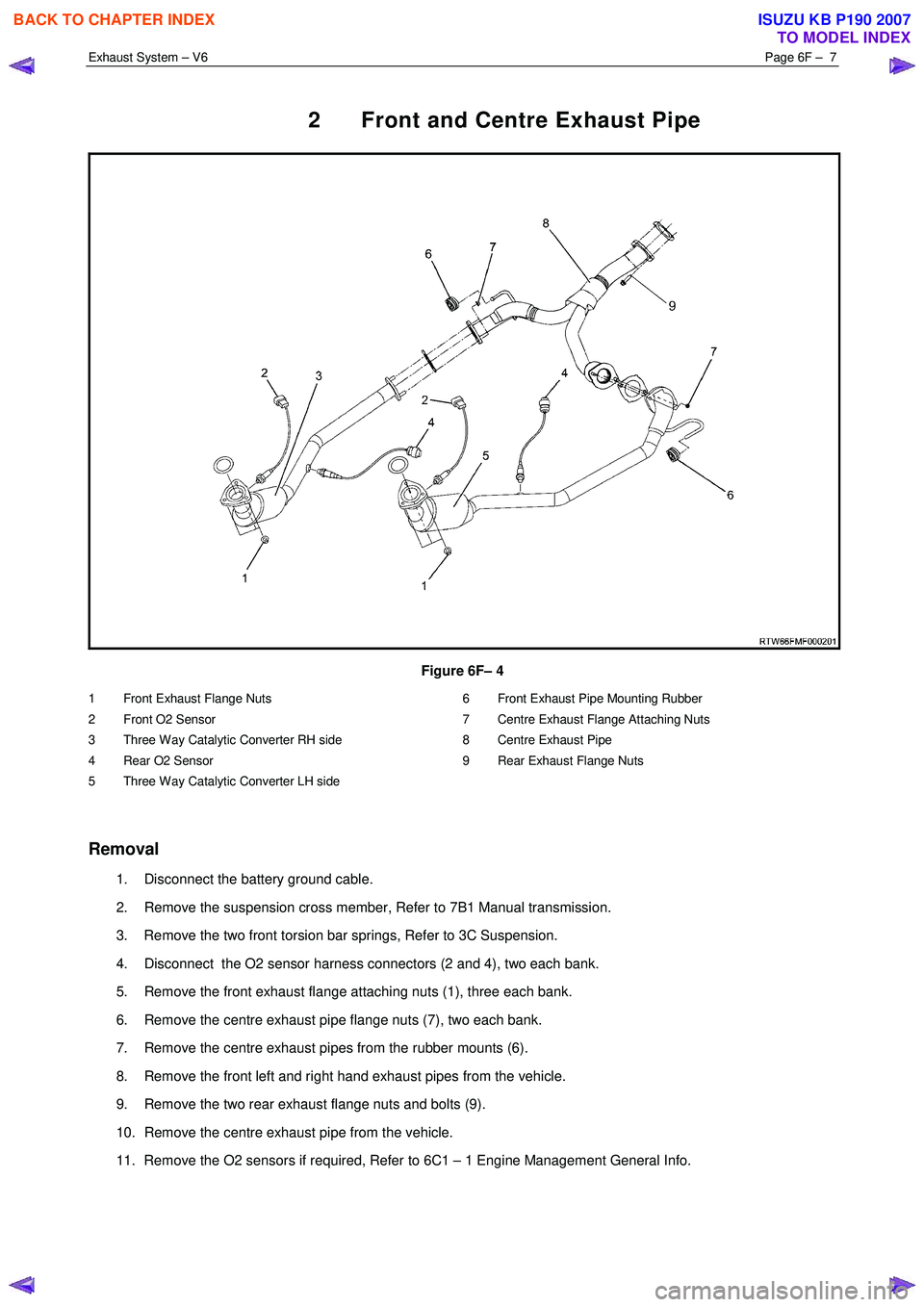
Figure 6F– 4
1 Front Exhaust Flange Nuts
2 Front O2 Sensor
3 Three Way Catalytic Converter RH side
4 Rear O2 Sensor
5 Three Way Catalytic Converter LH side 6 Front Exhaust Pipe Mounting Rubber
7 Centre Exhaust Flange Attaching Nuts
8 Centre Exhaust Pipe
9 Rear Exhaust Flange Nuts
Removal
1. Disconnect the battery ground cable.
2. Remove the suspension cross member, Refer to 7B1 Manual transmission.
3. Remove the two front torsion bar springs, Refer to 3C Suspension.
4. Disconnect the O2 sensor harness connectors (2 and 4), two each bank.
5. Remove the front exhaust flange attaching nuts (1), three each bank.
6. Remove the centre exhaust pipe flange nuts (7), two each bank.
7. Remove the centre exhaust pipes from the rubber mounts (6).
8. Remove the front left and right hand exhaust pipes from the vehicle.
9. Remove the two rear exhaust flange nuts and bolts (9).
10. Remove the centre exhaust pipe from the vehicle.
11. Remove the O2 sensors if required, Refer to 6C1 – 1 Engine Management General Info.
BACK TO CHAPTER INDEX
TO MODEL INDEX
ISUZU KB P190 2007
Page 3756 of 6020
Exhaust System – V6 Page 6F – 8
NOTE:
• Support the exhaust system at all times.
• Clean the threads of the attaching bolts, nuts,
studs and flanges with a suitable cleaning
solvent.
• Apply a high temperature anti-seize
compound to the manifold front pipe flange
joint studs, then align the flange over the
studs.
Reinstallation
1. Install any removed O2 sensors, Refer to 6C1 – 1 Engine Management General Info.
2. Position the centre exhaust pipe into location under the vehicle.
3. Install the two rear exhaust flange nuts and bolts (9).
4. Position the front exhaust pipes into location under the vehicle.
5. Install the centre exhaust pipes into the rubber mounts (6).
6. Install the exhaust flange fixing nuts (1), three each bank.
7. Install the rear exhaust pipe flange nuts (7), two each bank.
8. Reconnect the O2 sensor harness connectors (4), two each bank.
9. Install the two front torsion bar springs, Refer to 3C Suspension.
10. Install the suspension cross member, Refer to 7B1 Manual transmission.
11. Reconnect the battery ground cable.
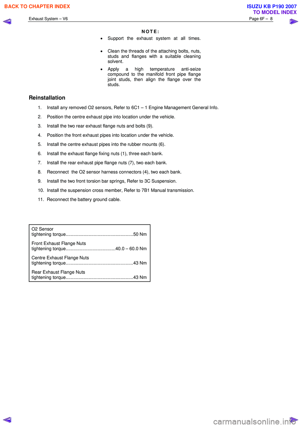
O2 Sensor
tightening torque.....................................................50 Nm
Front Exhaust Flange Nuts
tightening torque.......................................40.0 – 60.0 Nm
Centre Exhaust Flange Nuts
tightening torque.....................................................43 Nm
Rear Exhaust Flange Nuts
tightening torque.....................................................43 Nm
BACK TO CHAPTER INDEX
TO MODEL INDEX
ISUZU KB P190 2007
Page 3764 of 6020
Automatic Transmission – 4L60E – General Information Page 7C1–4
1.2 7C1 Automatic Transmission – 4L60E –
General Information
This section provides general information about the automatic transmission, including:
• A glossary of terms,
• Transmission identification information,
• Electrical overview of the Transmission Control Module (TCM),
• Some notes that address safe workshop practices,
• Service notes relating to fasteners and consumable items used at various stages throughout this section,
• Special tools required to work on the transmission,
• Fastener torque specifications, and
• Transmission specifications.
For all information relating to the mechanical construction and function of the 4L60E automatic transmission, refer to the
General Motors Powertrain Group Electronically Controlled Automatic Transmission Technician’s Guide.
This guide includes such information as:
• Transmission Cutaway Views,
• Principles of Operation,
• Power Flow,
• Complete Hydraulic Circuits,
• Bushing and Bearing Locations,
• Seal Locations and
• Illustrated Parts List.
NOTE
Specifications quoted in this General Motors
Powertrain Group Electronically Controlled
Automatic Transmission Technician Guide may
not be for the vehicle you are working on. For
correct specifications refer to
7 Transmission Specifications.
Recommendations
When servicing the transmission, all parts should be cleaned and inspected. Individual units should be reassembled
before disassembly of other units to avoid confusion and interchanging of parts.
a Thoroughly clean the transmission exterior before removal of any component.
b Disassembly and reassembly must be made on a clean work bench. Cleanliness is of the utmost importance, the bench tools and parts must be kept clean at all times.
c Before installing screws and other fasteners into aluminium parts, dip screw threads into transmission fluid to prevent galling aluminium threads and to prevent screws from seizing.
d To prevent thread stripping, always use a torque wrench when installing screws or nuts.
e If threads in aluminium parts are stripped or damaged, the parts can be made serviceable by the use of commercially available thread inserts.
f Protective tools must be used when assembling seals to prevent damage. The slightest flaw in the sealing surface of the seal can cause an oil leak.
g Aluminium castings and valve parts are very susceptible to nicks, burrs, etc. and should be handled with care.
h Expand Internal snap rings and compress external snap rings if they are to be re-used to ensure proper seating when reinstalled.
i Do not re-use removed O-rings, gaskets and oil seals.
j Teflon oil seal rings should not be removed unless damaged.
k During assembly of each unit, all internal moving parts must be lubricated with transmission fluid.
Oil Cooler Pipes
Should any transmission fluid cooling pipe suffer accidental damage, a genuine replacement pipe must be fitted. Refer to
the current release of PartFinder™ to determine the correct part number for the particular engine and pipe involved.
Reworking of damaged pipes or hand made replacements are not permitted.
BACK TO CHAPTER INDEX
TO MODEL INDEX
ISUZU KB P190 2007
Page 3765 of 6020
Automatic Transmission – 4L60E – General Information Page 7C1–5
Clean and Inspect
Do not use solvents on neoprene seals,
composition faced clutch plates or thrust
washers as damage to parts may occur.
After complete disassembly of a component, wash all metal parts in a clean solvent and dry with compressed air. Blow
oil passages out and check to make sure they are not obstructed, small passages should be checked with tag wire. All
parts should be inspected to determine if replacement is required.
Pay particular attention to the following:
• Inspect linkage and pivot points for excessive wear.
• Bearing and thrust surfaces of all parts should be checked for excessive wear and scoring.
• Check for broken seal rings, damaged ring lands and damaged threads.
• Inspect seals for damage.
• Mating surfaces of castings should be checked for burrs. Irregularities may be removed by lapping the surface with
emery paper laid on a flat surface, such as a piece of plate glass.
• Castings should be checked for cracks and porosity.
1.3 7C2 Automatic Transmission – 4L60E –
Electrical Diagnosis
For transmissions fitted to V6 engines, the electrical diagnosis is in this Section. A new electrical circuit and control
module has been introduced for automatic transmissions fitted to the V6 engines.
1.4 7C3 Automatic Transmission – 4L60E – Hydraulic and Mechanical Diagnosis
Information contained in 7C3 Automatic Transmission – 4L60E – Hydraulic and Mechanical Diagnosis will assist in the
diagnosis of the mechanical and hydraulic components in the 4L60E automatic transmission, while the transmission
remains installed on the vehicle.
Examples of the type of diagnostic information contained within this section are:
• transmission functional test,
• line pressure information,
• transmission fluid diagnosis,
• symptom diagnosis and
• shift speed charts.
1.5 7C4 Automatic Transmission – 4L60E –
On-vehicle Servicing
Information in 7C4 Automatic Transmission – 4L60E – On-vehicle Servicing covers transmission fluid level checking, as
well as specific information for servicing some components while the transmission remains installed on the vehicle. This
Section also covers the transmission removal and reinstallation to the vehicle.
BACK TO CHAPTER INDEX
TO MODEL INDEX
ISUZU KB P190 2007
Page 3766 of 6020
Automatic Transmission – 4L60E – General Information Page 7C1–6
2 General information
The hydra-matic 4L60E automatic transmission is fitted to vehicles with HFV6 engine. The mechanical and internal
electrical operation of the transmission unit is controlled by the transmission control module (TCM) for HFV6 engine.
• For information on the mechanical operation of the transmission, refer to General Motors Powertrain Group
Electronically Controlled Automatic Transmission Technician's Guide.
• For further information on the TCM, refer to 3.1 Transmission Control Module.
2.1 Transmission Control Module – HFV6
Vehicles fitted with a V6 engine and the 4L60E transmission have a new control module and data bus architecture from
previous models. This is due to the introduction of the new V6 engine. Mechanically, the transmission has not changed.
V6 equipped vehicles are now fitted with T42 – Delphi with GMPT software, transmission control module (TCM) to
control all transmission operations. For further information on the TCM and its operation, refer to 3 Transmission Control
Module Operation Overview.
2.2 Transmission Identification
The 4L60E automatic transmission application and identification can be determined from the stamping at the rear of the
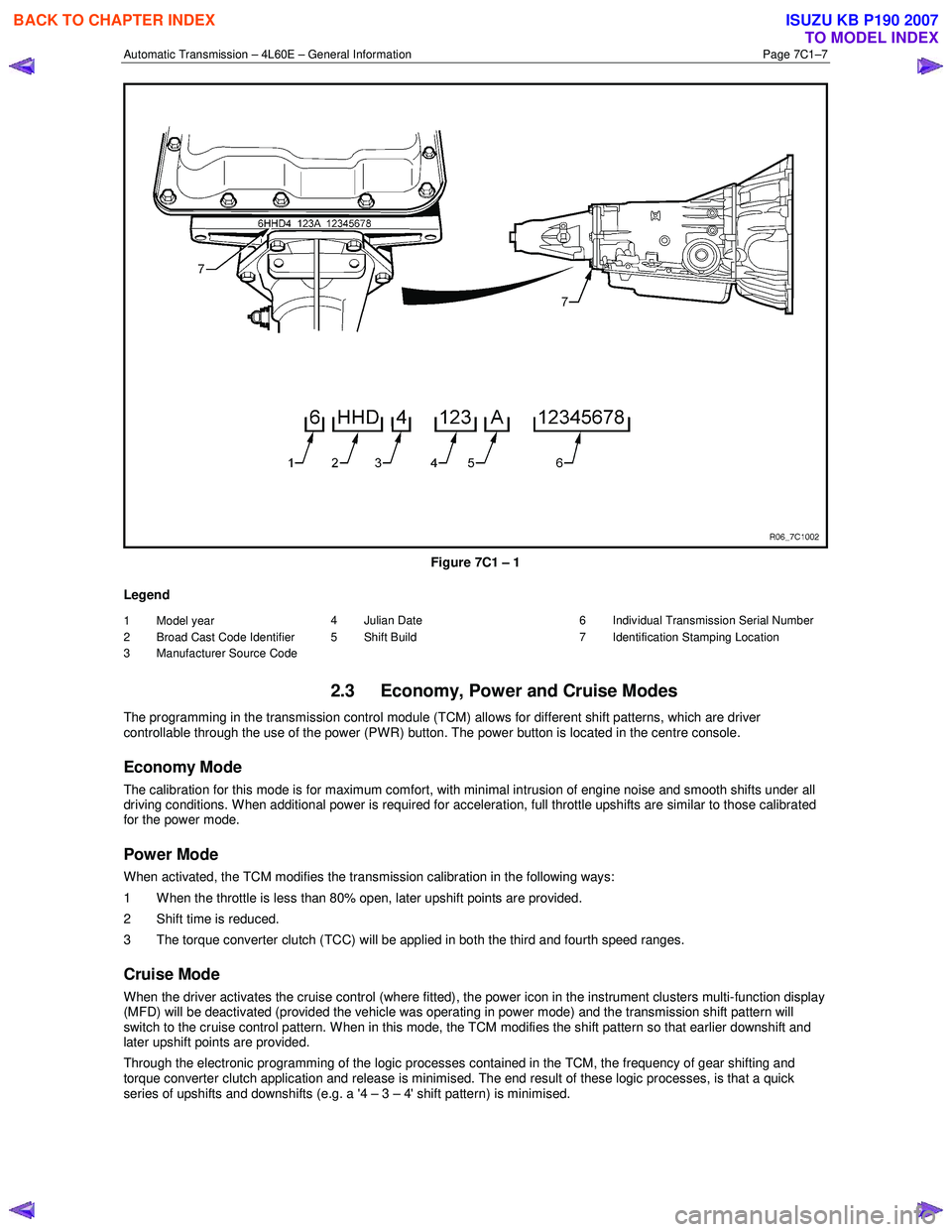
transmission , in the location (7) as shown in Figure 7C1 – 1.
Identification is as follows:
(1) model year,
• (6 = 2006).
(2) Broad Cast Code Identifier,
• HHD = RWD – 3.6 litre HFV6
• HLD = 4WD – 3.6 litre HFV6
(D = model 4L60E).
(3) Manufacturer Source Code,
• (4 = Ramos).
(4) Julian date (day of the year).
(5) Shift Build,
• 'A','B','J' = First shift,
• 'C','H','W' = Second shift.
(6) Individual transmission serial number.
BACK TO CHAPTER INDEX
TO MODEL INDEX
ISUZU KB P190 2007
Page 3767 of 6020
Automatic Transmission – 4L60E – General Information Page 7C1–7
Figure 7C1 – 1
Legend
1 Model year
2 Broad Cast Code Identifier
3 Manufacturer Source Code 4 Julian Date
5 Shift Build 6 Individual Transmission Serial Number
7 Identification Stamping Location
2.3 Economy, Power and Cruise Modes
The programming in the transmission control module (TCM) allows for different shift patterns, which are driver
controllable through the use of the power (PWR) button. The power button is located in the centre console.
Economy Mode
The calibration for this mode is for maximum comfort, with minimal intrusion of engine noise and smooth shifts under all
driving conditions. When additional power is required for acceleration, full throttle upshifts are similar to those calibrated
for the power mode.
Power Mode
When activated, the TCM modifies the transmission calibration in the following ways:
1 When the throttle is less than 80% open, later upshift points are provided.
2 Shift time is reduced.
3 The torque converter clutch (TCC) will be applied in both the third and fourth speed ranges.
Cruise Mode
When the driver activates the cruise control (where fitted), the power icon in the instrument clusters multi-function display
(MFD) will be deactivated (provided the vehicle was operating in power mode) and the transmission shift pattern will
switch to the cruise control pattern. When in this mode, the TCM modifies the shift pattern so that earlier downshift and
later upshift points are provided.
Through the electronic programming of the logic processes contained in the TCM, the frequency of gear shifting and
torque converter clutch application and release is minimised. The end result of these logic processes, is that a quick
series of upshifts and downshifts (e.g. a '4 – 3 – 4' shift pattern) is minimised.
BACK TO CHAPTER INDEX
TO MODEL INDEX
ISUZU KB P190 2007