2007 ISUZU KB P190 engine
[x] Cancel search: enginePage 3785 of 6020
Automatic Transmission – 4L60E – General Information Page 7C1–25
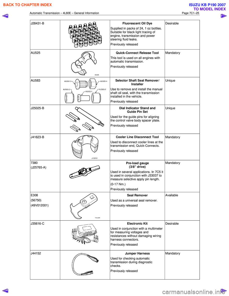
J28431-B
Fluorescent Oil Dye
Supplied in packs of 24, 1 oz bottles.
Suitable for black light tracing of
engine, transmission and power
steering fluid leaks.
Previously released Desirable
AU525
AU525 Quick-Connect Release Tool
This tool is used on all engines with
automatic transmission.
Previously released Mandatory
AU583 Selector Shaft Seal Remover/
Installer
Use to remove and install the manual
shaft oil seal, with the transmission
installed in the vehicle.
Previously released Unique
J25025-B
Dial Indicator Stand and
Guide Pin Set
Used for the guide pins for aligning
the control valve body spacer plate.
Previously released Unique
J41623-B
Cooler Line Disconnect Tool
Used to disconnect cooler lines at the
transmission end, Quick-Connects.
Previously released Mandatory
7380
(J25765-A)
Pre-load gauge
(3/8” drive)
Used in several applications. In 7C5 it
is used in conjunction with J33037 to
measure selective apply pin length.
(0-17 Nm.)
Previously released Mandatory
E308
(56750)
(49V012001)
Seal Remover
Used as a universal seal remover .
Previously released Available
J35616-C
Electronic Kit
Used in conjunction with a multimeter
for measuring voltages and
resistances without damaging wiring
harness connectors.
Previously released Desirable
J44152
Jumper Harness
Used for checking automatic
transmission during diagnostic
checks.
Previously released Mandatory
BACK TO CHAPTER INDEX
TO MODEL INDEX
ISUZU KB P190 2007
Page 3793 of 6020
Automatic Transmission – 4L60E – Electrical Diagnosis Page 7C2–7
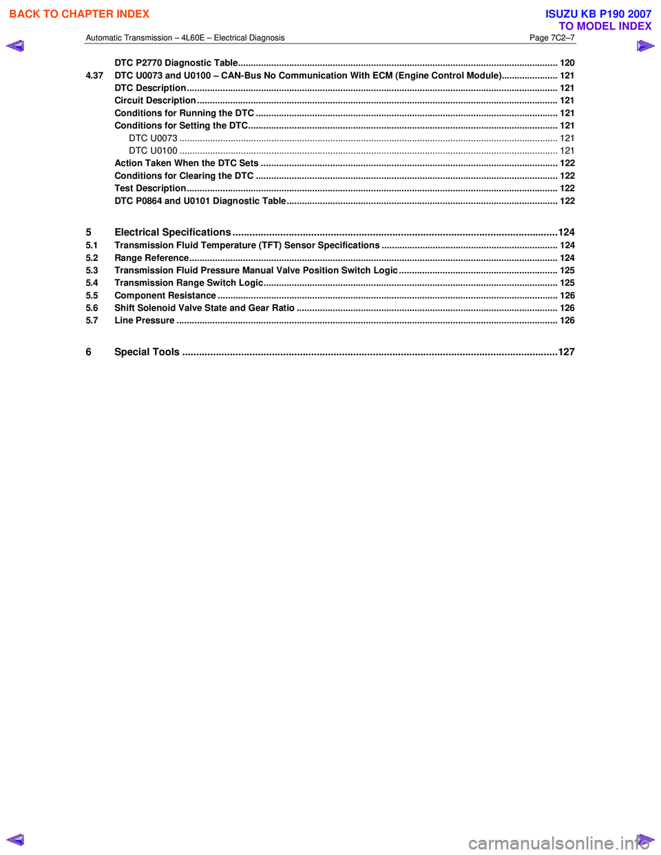
DTC P2770 Diagnostic Table............................................................................................................................. 120
4.37 DTC U0073 and U0100 – CAN-Bus No Communication With ECM (Engine Control Module)...................... 121
DTC Description ................................................................................................................................................. 121
Circuit Description ............................................................................................................................................. 121
Conditions for Running the DTC ................................................................................................. ..................... 121
Conditions for Setting the DTC......................................................................................................................... 121
DTC U0073 .................................................................................................................................................... 121
DTC U0100 .................................................................................................................................................... 121
Action Taken When the DTC Sets ................................................................................................. ................... 122
Conditions for Clearing the DTC ...................................................................................................................... 122
Test Description ................................................................................................................................................. 122
DTC P0864 and U0101 Diagnostic Table........................................................................................... ............... 122
5 Electrical Specifications ....................................................................................................................124
5.1 Transmission Fluid Temperature (TFT) Sensor Specifications ..................................................................... 124
5.2 Range Reference................................................................................................................................................ 124
5.3 Transmission Fluid Pressure Manual Valve Position Switch Logic .............................................................. 125
5.4 Transmission Range Switch Logic................................................................................................................... 125
5.5 Component Resistance ..................................................................................................................................... 126
5.6 Shift Solenoid Valve State and Gear Ratio ...................................................................................................... 126
5.7 Line Pressure ..................................................................................................................................................... 126
6 Special Tools ......................................................................................................................................127
BACK TO CHAPTER INDEX
TO MODEL INDEX
ISUZU KB P190 2007
Page 3794 of 6020
Automatic Transmission – 4L60E – Electrical Diagnosis Page 7C2–8
1 General Information
1.1 Introduction
This Section covers the electrical diagnostic for the 4L60E automatic transmission when mated to a V6 engine.
1.2 General Description
The 4L60E automatic transmission incorporates electronic controls that utilise a transmission control module (TCM) to
control shift points through:
• the 1-2 and 2-3 shift solenoid valves,
• the 3-2 downshift solenoid valve,
• a torque converter clutch (TCC) solenoid valve,
• apply and release through the TCC pulse width modulated (PW M) solenoid valve, and
• line pressure through the pressure control (PC) solenoid valve.
Electrical signals from various sensors provide information to the TCM about the following:
• vehicle speed,
• throttle position,
• engine coolant temperature,
• transmission fluid temperature,
• gear range selector position,
• engine speed,
• converter turbine speed, and
• engine load braking and operating mode.
The TCM uses this information to determine the precise moment to upshift or downshift, apply or release the TCC and
what fluid pressure is needed to apply the clutches. This type of control provides consistent and precise shift points and
shift quality based on the operating conditions of the vehicle.
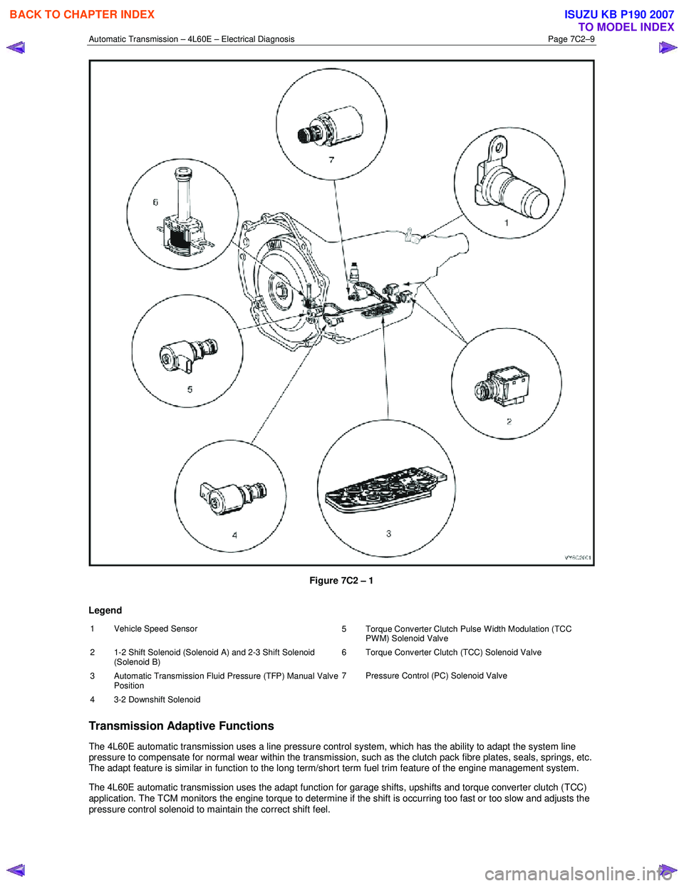
Figure 7C2 – 1 shows the location of the internal electronic components in the transmission.
BACK TO CHAPTER INDEX
TO MODEL INDEX
ISUZU KB P190 2007
Page 3795 of 6020
Automatic Transmission – 4L60E – Electrical Diagnosis Page 7C2–9
Figure 7C2 – 1
Legend
1 Vehicle Speed Sensor 5 Torque Converter Clutch Pulse Width Modulation (TCC
PWM) Solenoid Valve
2 1-2 Shift Solenoid (Solenoid A) and 2-3 Shift Solenoid (Solenoid B) 6 Torque Converter Clutch (TCC) Solenoid Valve
3
Automatic Transmission Fluid Pressure (TFP) Manual Valve
Position 7 Pressure Control (PC) Solenoid Valve
4 3-2 Downshift Solenoid
Transmission Adaptive Functions
The 4L60E automatic transmission uses a line pressure control system, which has the ability to adapt the system line
pressure to compensate for normal wear within the transmission, such as the clutch pack fibre plates, seals, springs, etc.
The adapt feature is similar in function to the long term/short term fuel trim feature of the engine management system.
The 4L60E automatic transmission uses the adapt function for garage shifts, upshifts and torque converter clutch (TCC)
application. The TCM monitors the engine torque to determine if the shift is occurring too fast or too slow and adjusts the
pressure control solenoid to maintain the correct shift feel.
BACK TO CHAPTER INDEX
TO MODEL INDEX
ISUZU KB P190 2007
Page 3796 of 6020
Automatic Transmission – 4L60E – Electrical Diagnosis Page 7C2–10
Limp Home Mode Description
If a major electrical system failure occurs which could affect vehicle safety or damage the transmission during normal
operation, the TCM enters a limp home mode. In the limp home mode, the transmission operates in the following
manner:
• The pressure control solenoid is off and the line pressure is at maximum to minimise clutch slippage.
• The TCC solenoid is off, therefore the torque converter clutch is disabled.
• The two shift solenoids are turned off. The transmission will operate in fourth gear if the vehicle has successfully
completed a 1-2 upshift in the current ignition cycle. If the vehicle has not completed a 1-2 upshift in the current
ignition cycle, the transmission will operate in third gear. If the transmission is operating in fourth gear, third gear
may be obtained if the engine is stopped briefly and re-started.
In limp home mode, the gear selector lever is ineffective at selecting forward gear ranges. In third or fourth gear, heat
builds up in the transmission quickly, particularly in stop and go traffic. Excessive heat build-up may cause transmission
failure if the vehicle is driven for extended distances in limp home mode.
1.3 Transmission Indicators and Messages
For information pertaining to the instrument cluster and the transmission information it displays, refer to the RA Rodeo
Owner Handbook.
1.4 Electronic Component Description
For all other electrical components not covered in this section, refer to General Motors Powertrain Group Electronically
Controlled Automatic Transmission Technician's Guide.
Transmission Control Module (TCM)
The Transmission Control Module (TCM) is located under the instrument panel, next to the brake pedal assembly and
connects directly to the transmission wiring harness. A single 49-way connector is used to make the connection between
the vehicle wiring harness and the TCM.
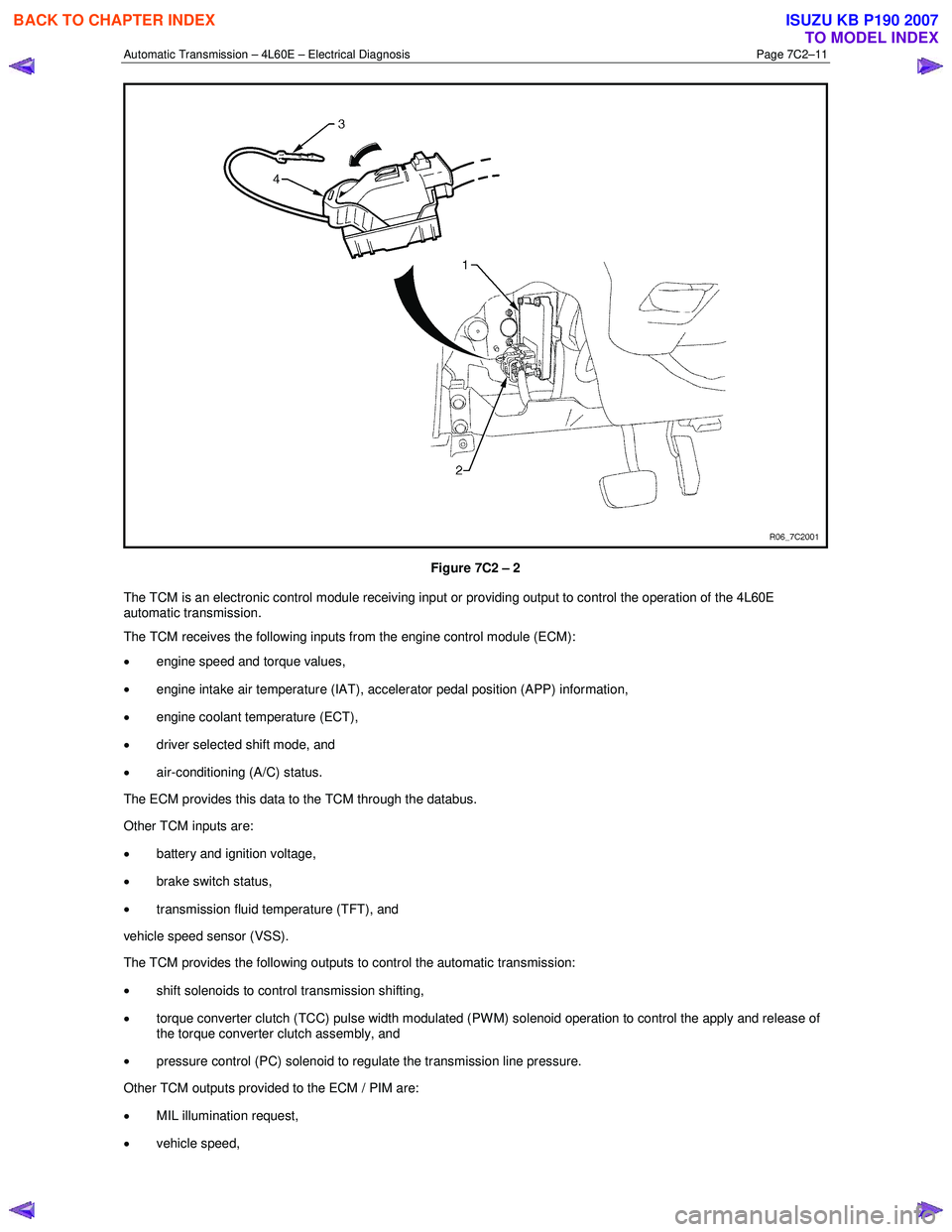
To access the connector for diagnosis:
1 Ensure the ignition switch is in the OFF position.
2 Disconnect the connector (1) from the transmission control module (TCM) (2) as follows, refer to Figure 7C2 – 2: a remove the securing pin (3),
b press the locking tab and swing the lever (4) to free the connector,
c remove the connector.
BACK TO CHAPTER INDEX
TO MODEL INDEX
ISUZU KB P190 2007
Page 3797 of 6020
Automatic Transmission – 4L60E – Electrical Diagnosis Page 7C2–11
Figure 7C2 – 2
The TCM is an electronic control module receiving input or providing output to control the operation of the 4L60E
automatic transmission.
The TCM receives the following inputs from the engine control module (ECM):
• engine speed and torque values,
• engine intake air temperature (IAT), accelerator pedal position (APP) information,
• engine coolant temperature (ECT),
• driver selected shift mode, and
• air-conditioning (A/C) status.
The ECM provides this data to the TCM through the databus.
Other TCM inputs are:
• battery and ignition voltage,
• brake switch status,
• transmission fluid temperature (TFT), and
vehicle speed sensor (VSS).
The TCM provides the following outputs to control the automatic transmission:
• shift solenoids to control transmission shifting,
• torque converter clutch (TCC) pulse width modulated (PW M) solenoid operation to control the apply and release of
the torque converter clutch assembly, and
• pressure control (PC) solenoid to regulate the transmission line pressure.
Other TCM outputs provided to the ECM / PIM are:
• MIL illumination request,
• vehicle speed,
BACK TO CHAPTER INDEX
TO MODEL INDEX
ISUZU KB P190 2007
Page 3800 of 6020
Automatic Transmission – 4L60E – Electrical Diagnosis Page 7C2–14
3 Tech 2 Information
3.1 Tech 2 Diagnostics
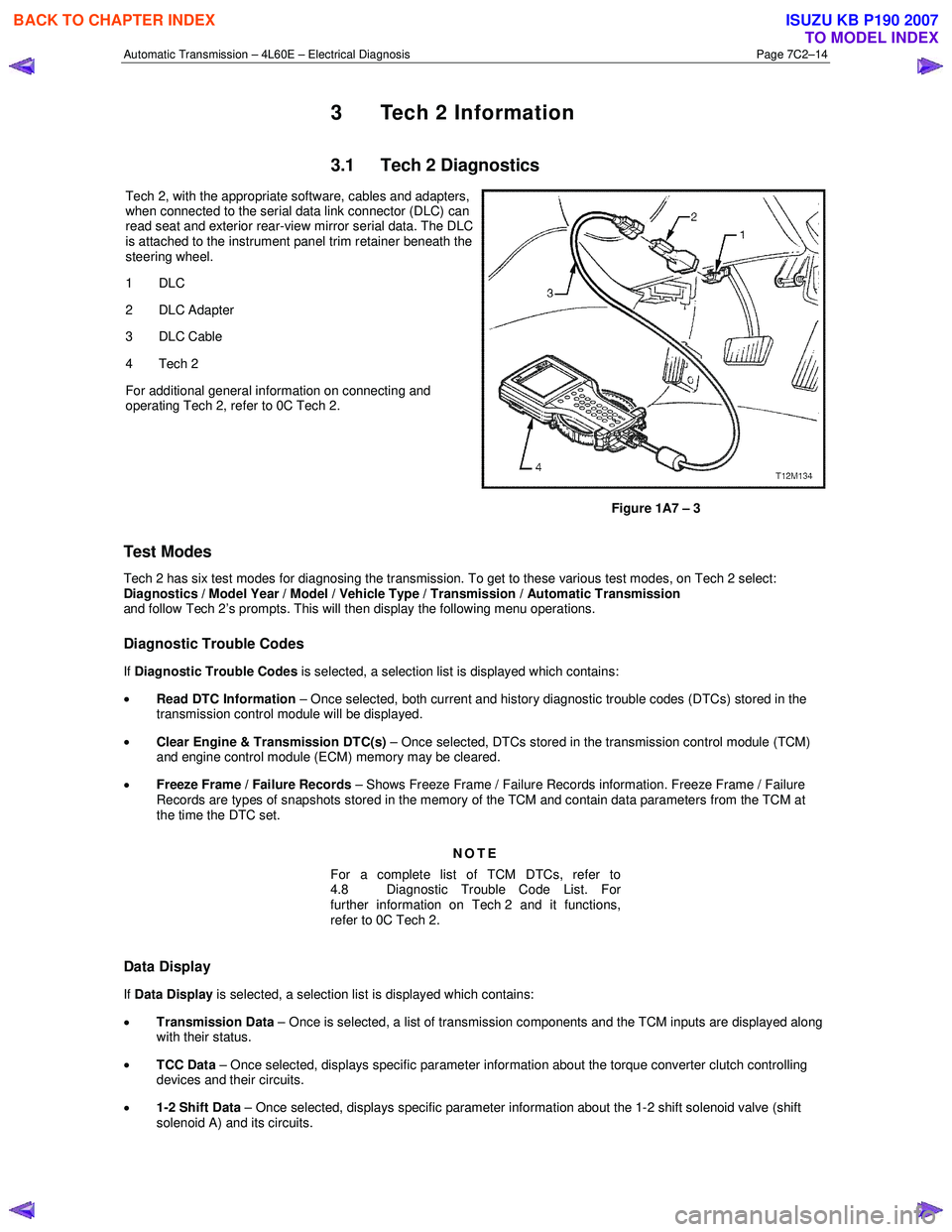
Tech 2, with the appropriate software, cables and adapters,
when connected to the serial data link connector (DLC) can
read seat and exterior rear-view mirror serial data. The DLC
is attached to the instrument panel trim retainer beneath the
steering wheel.
1 DLC
2 DLC Adapter
3 DLC Cable
4 Tech 2
For additional general information on connecting and
operating Tech 2, refer to 0C Tech 2.
Figure 1A7 – 3
Test Modes
Tech 2 has six test modes for diagnosing the transmission. To get to these various test modes, on Tech 2 select:
Diagnostics / Model Year / Model / Vehicle Type / Transmission / Automatic Transmission
and follow Tech 2’s prompts. This will then display the following menu operations.
Diagnostic Trouble Codes
If Diagnostic Trouble Codes is selected, a selection list is displayed which contains:
• Read DTC Information – Once selected, both current and history diagnostic trouble codes (DTCs) stored in the
transmission control module will be displayed.
• Clear Engine & Transmission DTC(s) – Once selected, DTCs stored in the transmission control module (TCM)
and engine control module (ECM) memory may be cleared.
• Freeze Frame / Failure Records – Shows Freeze Frame / Failure Records information. Freeze Frame / Failure
Records are types of snapshots stored in the memory of the TCM and contain data parameters from the TCM at
the time the DTC set.
NOTE
For a complete list of TCM DTCs, refer to
4.8 Diagnostic Trouble Code List. For
further information on Tech 2 and it functions,
refer to 0C Tech 2.
Data Display
If Data Display is selected, a selection list is displayed which contains:
• Transmission Data – Once is selected, a list of transmission components and the TCM inputs are displayed along
with their status.
• TCC Data – Once selected, displays specific parameter information about the torque converter clutch controlling
devices and their circuits.
• 1-2 Shift Data – Once selected, displays specific parameter information about the 1-2 shift solenoid valve (shift
solenoid A) and its circuits.
BACK TO CHAPTER INDEX
TO MODEL INDEX
ISUZU KB P190 2007
Page 3801 of 6020
Automatic Transmission – 4L60E – Electrical Diagnosis Page 7C2–15
• 2-3 Shift Data – Once this mode is selected, displays specific parameter information about the 2-3 shift solenoid
valve (shift solenoid B) and its circuits.
• 3-4 Shift Data – Once selected, displays information on 3-4 shift timing.
• 3-2 Downshift Data – Once selected, displays information on 3-2 downshift timing.
• Pressure Control Solenoid Data – Once selected, displays specific parameter information about the PC solenoid
and its circuits.
• Transmission Adapts – Once selected, it has further sub menus:
• 1-2 Adapt Data – In this mode Tech 2 continuously monitors and displays 1-2 TAP cell data parameters.
• 2-3 Adapt Data –In this mode Tech 2 continuously monitors and displays 2-3 TAP cell data parameters.
• 3-4 Adapt Data –In this mode Tech 2 continuously monitors and displays 3-4 TAP cell data parameters.
• Steady State Adapt Data – In this mode Tech 2 continuously monitors and displays Steady State TAP data
parameters.
• System Identification: In this mode, Tech 2 will display the transmission identification screen. The following items
will be displayed; Identifier, Partnumber, Hardware Partnumber, Alpha Code, Software Version Number, Software
Partnumber, VIN Digit 1-10, VIN Digit 11-17.
NOTE
Further information about the Data Display mode
and the data parameter is contained in
3.2 Data Display.
Snapshot
In this test mode, Tech 2 captures TCM data before and after a forced manual trigger.
Additional Functions
If Additional Functions is selected, a selections list is displayed which contains:
• System Identification – In this mode, Tech 2 will display the transmission identification screen. The following items
will be displayed; Identifier, Partnumber, Hardware Partnumber, Alpha Code, Software Version Number, Software
Partnumber.
Miscellaneous Tests
If Miscellaneous Functions is selected, a selections list is displayed which contains:
• TCC Solenoid –Tech 2 can command the TCC solenoid on and off. Tech 2 will display whether the TCC solenoid
is active or inactive.
• TCC PWN Solenoid – Tech 2 can command the TCC PWM solenoid on and off. Tech 2 will display whether the
TCC PWM solenoid is active or inactive and torque percentage.
• TCC Apply – Tech 2 can command the TCC on when the vehicle is above 50 km/h.
• Shift Solenoid A – Tech 2 can command the shift solenoid A (1-2 shift solenoid) on and off.
• Shift Solenoid B – Tech 2 can command the shift solenoid B (2-3 shift solenoid) on and off.
• 3/2 Downshift Solenoid – Tech 2 can command the 3/2 downshift solenoid (3-2 shift solenoid) on and off.
• Gear Control – Tech 2 can incrementally command shift solenoid states to correspond to relative gear states. The
TCM will only allow single shift increments or decrements and does not allow a shift if it causes the engine RPM to
exceed a calibrated limit.
• Pressure Control Solenoid – This function allows the user to control state of the pressure control solenoid in
increments of 100 mA.
NOTE
For operating parameters of the
Miscellaneous Test, refer to 3.4 Miscellaneous Tests.
BACK TO CHAPTER INDEX
TO MODEL INDEX
ISUZU KB P190 2007