2007 ISUZU KB P190 engine
[x] Cancel search: enginePage 3736 of 6020
Powertrain Interface Module – V6 Page 6E1–75
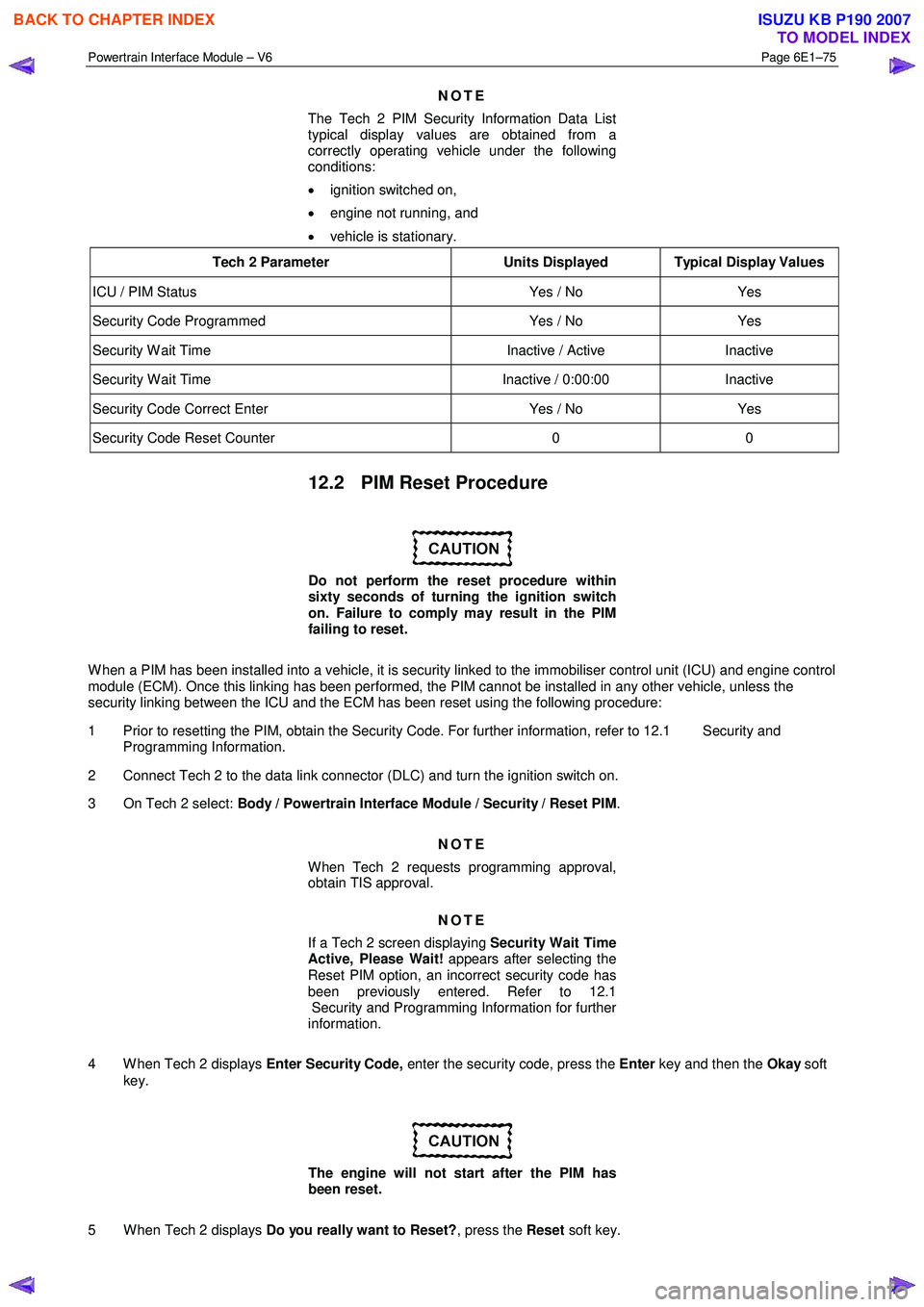
NOTE
The Tech 2 PIM Security Information Data List
typical display values are obtained from a
correctly operating vehicle under the following
conditions:
• ignition switched on,
• engine not running, and
• vehicle is stationary.
Tech 2 Parameter Units Displayed Typical Display Values
ICU / PIM Status Yes / No Yes
Security Code Programmed Yes / No Yes
Security W ait Time Inactive / Active Inactive
Security W ait Time Inactive / 0:00:00 Inactive
Security Code Correct Enter Yes / No Yes
Security Code Reset Counter 0 0
12.2 PIM Reset Procedure
Do not perform the reset procedure within
sixty seconds of turning the ignition switch
on. Failure to comply may result in the PIM
failing to reset.
W hen a PIM has been installed into a vehicle, it is security linked to the immobiliser control unit (ICU) and engine control
module (ECM). Once this linking has been performed, the PIM cannot be installed in any other vehicle, unless the
security linking between the ICU and the ECM has been reset using the following procedure:
1 Prior to resetting the PIM, obtain the Security Code. For further information, refer to 12.1 Security and Programming Information.
2 Connect Tech 2 to the data link connector (DLC) and turn the ignition switch on.
3 On Tech 2 select: Body / Powertrain Interface Module / Security / Reset PIM .
NOTE
When Tech 2 requests programming approval,
obtain TIS approval.
NOTE
If a Tech 2 screen displaying Security Wait Time
Active, Please Wait! appears after selecting the
Reset PIM option, an incorrect security code has
been previously entered. Refer to 12.1
Security and Programming Information for further
information.
4 W hen Tech 2 displays Enter Security Code, enter the security code, press the Enter key and then the Okay soft
key.
The engine will not start after the PIM has
been reset.
5 W hen Tech 2 displays Do you really want to Reset? , press the Reset soft key.
BACK TO CHAPTER INDEX
TO MODEL INDEX
ISUZU KB P190 2007
Page 3738 of 6020
Powertrain Interface Module – V6 Page 6E1–77
Do not turn the ignition switch off within 60
seconds of programming the VIN. Failure to
comply may result in the changes failing to be
programmed into the PIM.
5 W hen notified that the programming was successful, press the Confirm soft key to return to the Tech 2 Program
screen.
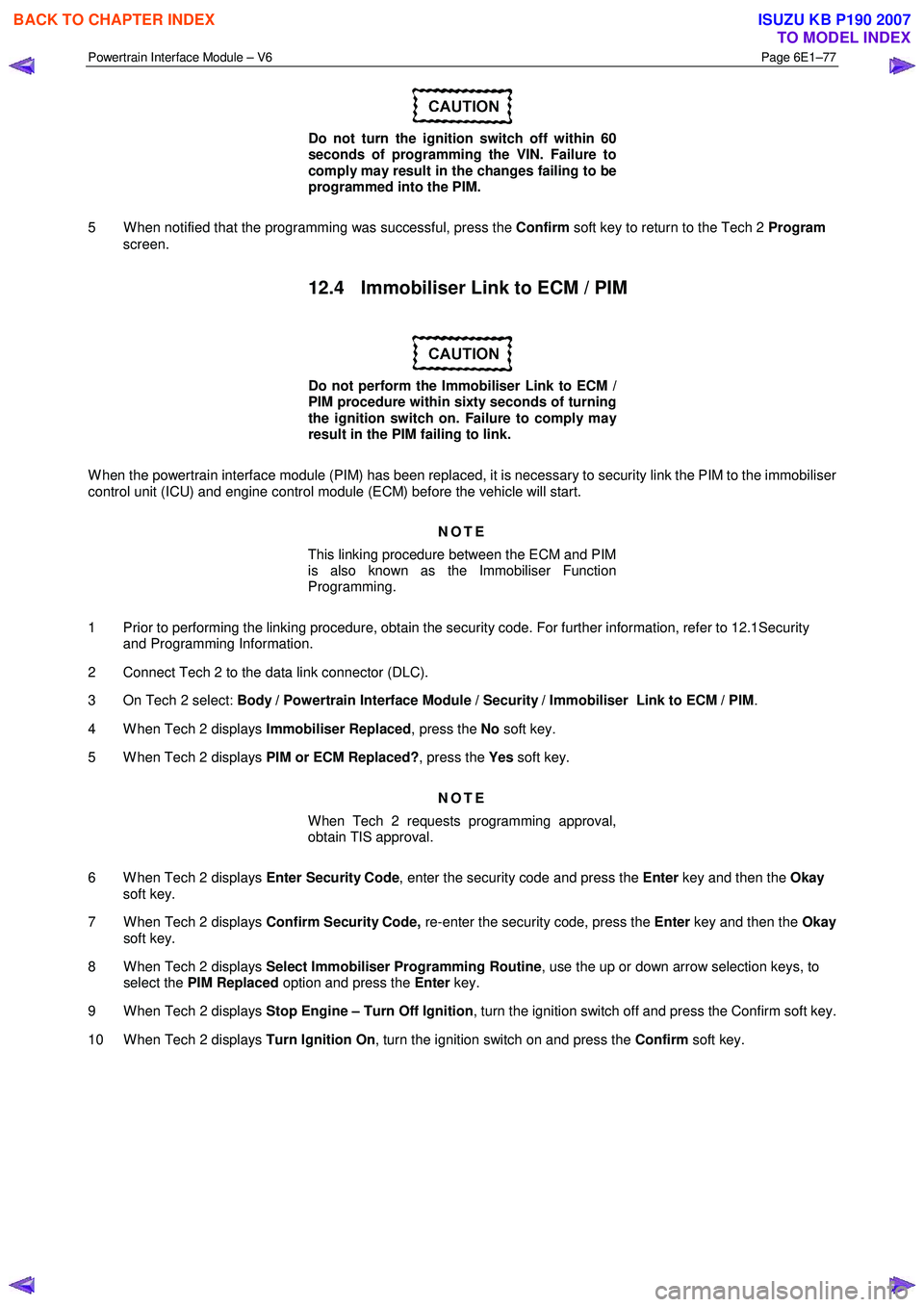
12.4 Immobiliser Link to ECM / PIM
Do not perform the Immobiliser Link to ECM /
PIM procedure within sixty seconds of turning
the ignition switch on. Failure to comply may
result in the PIM failing to link.
W hen the powertrain interface module (PIM) has been replaced, it is necessary to security link the PIM to the immobiliser
control unit (ICU) and engine control module (ECM) before the vehicle will start.
NOTE
This linking procedure between the ECM and PIM
is also known as the Immobiliser Function
Programming.
1 Prior to performing the linking procedure, obtain the security code. For further information, refer to 12.1Security and Programming Information.
2 Connect Tech 2 to the data link connector (DLC).
3 On Tech 2 select: Body / Powertrain Interface Module / Security / Immobiliser Link to ECM / PIM .
4 W hen Tech 2 displays Immobiliser Replaced, press the No soft key.
5 W hen Tech 2 displays PIM or ECM Replaced?, press the Yes soft key.
NOTE
When Tech 2 requests programming approval,
obtain TIS approval.
6 W hen Tech 2 displays Enter Security Code, enter the security code and press the Enter key and then the Okay
soft key.
7 W hen Tech 2 displays Confirm Security Code, re-enter the security code, press the Enter key and then the Okay
soft key.
8 W hen Tech 2 displays Select Immobiliser Programming Routine , use the up or down arrow selection keys, to
select the PIM Replaced option and press the Enter key.
9 W hen Tech 2 displays Stop Engine – Turn Off Ignition , turn the ignition switch off and press the Confirm soft key.
10 W hen Tech 2 displays Turn Ignition On, turn the ignition switch on and press the Confirm soft key.
BACK TO CHAPTER INDEX
TO MODEL INDEX
ISUZU KB P190 2007
Page 3740 of 6020
Powertrain Interface Module – V6 Page 6E1–79
13 Powertrain Interface Module –
Tech 2 Functions
13.1 Introduction
Do not use a Tech 2 that displays faulty data;
have the Tech 2 repaired. The use of a faulty
Tech 2 can result in misdiagnosis and the
unnecessary replacement of parts.
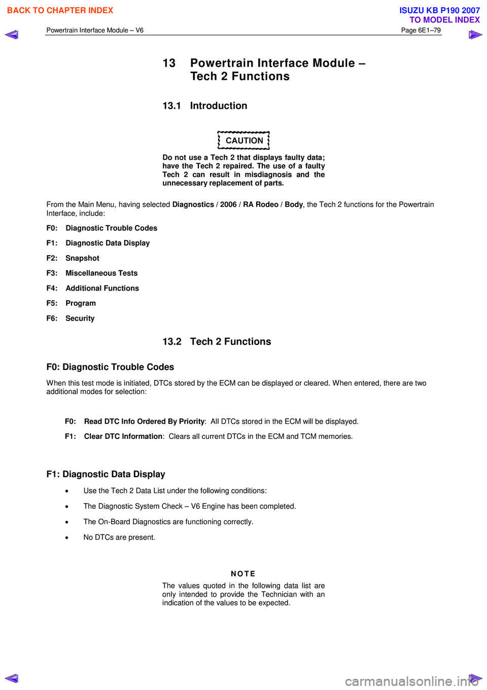
From the Main Menu, having selected Diagnostics / 2006 / RA Rodeo / Body , the Tech 2 functions for the Powertrain
Interface, include:
F0: Diagnostic Trouble Codes
F1: Diagnostic Data Display
F2: Snapshot
F3: Miscellaneous Tests
F4: Additional Functions
F5: Program
F6: Security
13.2 Tech 2 Functions
F0: Diagnostic Trouble Codes
W hen this test mode is initiated, DTCs stored by the ECM can be displayed or cleared. W hen entered, there are two
additional modes for selection:
F0: Read DTC Info Ordered By Priority : All DTCs stored in the ECM will be displayed.
F1: Clear DTC Information : Clears all current DTCs in the ECM and TCM memories.
F1: Diagnostic Data Display
• Use the Tech 2 Data List under the following conditions:
• The Diagnostic System Check – V6 Engine has been completed.
• The On-Board Diagnostics are functioning correctly.
• No DTCs are present.
NOTE
The values quoted in the following data list are
only intended to provide the Technician with an
indication of the values to be expected.
BACK TO CHAPTER INDEX
TO MODEL INDEX
ISUZU KB P190 2007
Page 3742 of 6020
Powertrain Interface Module – V6 Page 6E1–81
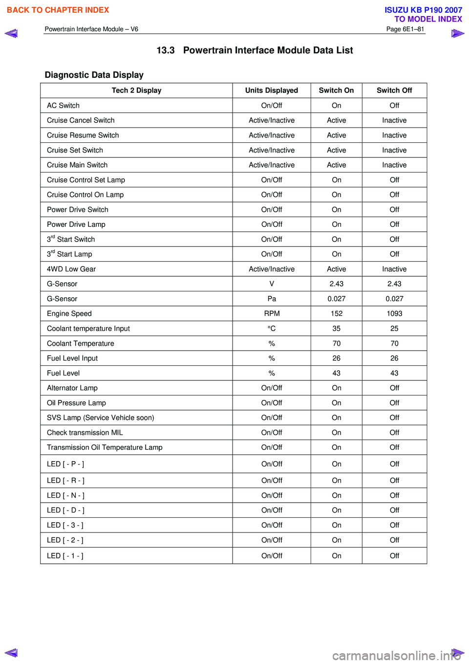
13.3 Powertrain Interface Module Data List
Diagnostic Data Display
Tech 2 Display Units Displayed Switch On Switch Off
AC Switch On/Off On Off
Cruise Cancel Switch Active/Inactive Active Inactive
Cruise Resume Switch Active/Inactive Active Inactive
Cruise Set Switch Active/Inactive Active Inactive
Cruise Main Switch Active/Inactive Active Inactive
Cruise Control Set Lamp On/Off On Off
Cruise Control On Lamp On/Off On Off
Power Drive Switch On/Off On Off
Power Drive Lamp On/Off On Off
3rd Start Switch On/Off On Off
3rd Start Lamp On/Off On Off
4W D Low Gear Active/Inactive Active Inactive
G-Sensor V 2.43 2.43
G-Sensor Pa 0.027 0.027
Engine Speed RPM 152 1093
Coolant temperature Input °C 35 25
Coolant Temperature % 70 70
Fuel Level Input % 26 26
Fuel Level % 43 43
Alternator Lamp On/Off On Off
Oil Pressure Lamp On/Off On Off
SVS Lamp (Service Vehicle soon) On/Off On Off
Check transmission MIL On/Off On Off
Transmission Oil Temperature Lamp On/Off On Off
LED [ - P - ] On/Off On Off
LED [ - R - ] On/Off On Off
LED [ - N - ] On/Off On Off
LED [ - D - ] On/Off On Off
LED [ - 3 - ] On/Off On Off
LED [ - 2 - ] On/Off On Off
LED [ - 1 - ] On/Off On Off
BACK TO CHAPTER INDEX
TO MODEL INDEX
ISUZU KB P190 2007
Page 3744 of 6020
Powertrain Interface Module – V6 Page 6E1–83
13.5 Security
F0: Immobiliser Link To ECM/PIM
Should the ECM, PIM or ICU be replaced, the modules must be security linked to each other. If this linking
procedure is not performed, the vehicle will not crank nor run. For additional information relating to Tech 2
and the linking procedure, refer to 11A – Immobiliser.
NOTE
After an ECU reset, the ignition switch must be
turned Off for at least 10 seconds and then
turned On for at least one minute, before
attempting communication between Tech 2 and
the ECU.
Preconditions: TIS approval (TIS 2000 Security Access) must be obtained, the four digit security number
entered into Tech 2 and the theft deterrent system disarmed. Then the ignition must be turned ‘On’, using a
programmed remote coded key.
F1: Reset PIM
This function erases the security link between the Engine Control Module (ECM) and the Powertrain Interface Modules (PIM). If this procedure is performed, the engine will not crank nor run. A ICU Link to ECM/PIM
procedure will need to be performed. For additional information relating to the ICU Link to ECM/PIM
procedure, refer to 11A – Immobiliser.
NOTE
After an ECU reset, the ignition switch must be
turned Off for at least 10 seconds and then
turned On for at least one minute, before
attempting communication between Tech 2 and
the ECU.
Preconditions: The four digit security code must be entered into Tech 2 and the ignition switched ‘On’ with a
programmed remote coded key.
F2: Security Information
The security code is required when performing certain PIM, ICU and ECM programming functions. W hen Tech 2 requests the security code to be entered, and an incorrect code is entered, the PIM will go into a
security wait time stage. This wait time stage will prevent any further attempts to enter the security code until
the wait time has elapsed.
Should a second incorrect security code be entered after the initial wait time has elapsed, the PIM will go into a second wait time stage. The wait time will increase each time an incorrect code is entered. W hen the
correct code is entered the wait time will reset back to its original value of 10 seconds.
NOTE
The ignition switch must be in the ON position
with the battery connected during the wait time
period.
The wait time stages are as follows: • Stage 1 = 10 seconds.
• Stage 2 = 10 seconds.
• Stage 3 = 10 minutes.
• Stage 4 = 20 minutes.
• Stage 5 = 40 minutes.
• Stage 5 = 80 minutes.
BACK TO CHAPTER INDEX
TO MODEL INDEX
ISUZU KB P190 2007
Page 3745 of 6020
Powertrain Interface Module – V6 Page 6E1–84
Tech 2 PIM Security Information Data List
The Tech 2 PIM Security Information Data List displays the PIM's current security status.
To view the data list:
1 Connect Tech 2 to the data link connector (DLC) and turn the ignition switch on.
2 On Tech 2 select: Body / Powertrain Interface Module / Security / Security Information .
NOTE
The Tech 2 PIM Security Information Data List
typical display values are obtained from a
correctly operating vehicle under the following
conditions:
• ignition switched on,
• engine not running, and
• vehicle is stationary.
Tech 2 Parameter Units Displayed Typical Display Values
Security Code Programmed Yes / No Yes
Security W ait Time Inactive / Active Inactive
Security W ait Time Inactive / 0:00:00 Inactive
Security Code Reset Counter 0 0
BACK TO CHAPTER INDEX
TO MODEL INDEX
ISUZU KB P190 2007
Page 3746 of 6020

Powertrain Interface Module – V6 Page 6E1–85
14 Specifications
Powertrain Interface Module Bus Cut-off Resistor.................................... 120 Ω
Engine Control Module Bus Cut-off Resistor ............................................ 120 Ω
BACK TO CHAPTER INDEX
TO MODEL INDEX
ISUZU KB P190 2007
Page 3750 of 6020
Exhaust System – V6 Page 6F – 2
1 General Information
Information contained within this section describes the general exhaust system.
1.1 Emission Reductions
Through developments in various vehicle emissions reduction systems, significant reductions in emissions have been
achieved. The developments have been primarily concerned with refinements in engine calibration and the optimisation
of exhaust system catalytic converter configurations.
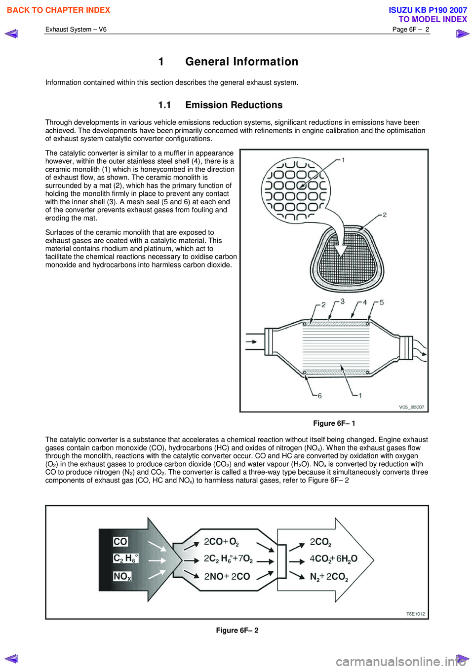
The catalytic converter is similar to a muffler in appearance
however, within the outer stainless steel shell (4), there is a
ceramic monolith (1) which is honeycombed in the direction
of exhaust flow, as shown. The ceramic monolith is
surrounded by a mat (2), which has the primary function of
holding the monolith firmly in place to prevent any contact
with the inner shell (3). A mesh seal (5 and 6) at each end
of the converter prevents exhaust gases from fouling and
eroding the mat.
Surfaces of the ceramic monolith that are exposed to
exhaust gases are coated with a catalytic material. This
material contains rhodium and platinum, which act to
facilitate the chemical reactions necessary to oxidise carbon
monoxide and hydrocarbons into harmless carbon dioxide.
Figure 6F– 1
The catalytic converter is a substance that accelerates a chemical reaction without itself being changed. Engine exhaust
gases contain carbon monoxide (CO), hydrocarbons (HC) and oxides of nitrogen (NO
x). W hen the exhaust gases flow
through the monolith, reactions with the catalytic converter occur. CO and HC are converted by oxidation with oxygen
(O
2) in the exhaust gases to produce carbon dioxide (CO2) and water vapour (H2O). NOx is converted by reduction with
CO to produce nitrogen (N
2) and CO2. The converter is called a three-way type because it simultaneously converts three
components of exhaust gas (CO, HC and NO
x) to harmless natural gases, refer to Figure 6F– 2
Figure 6F– 2
BACK TO CHAPTER INDEX
TO MODEL INDEX
ISUZU KB P190 2007