2007 ISUZU KB P190 cooling
[x] Cancel search: coolingPage 3408 of 6020
Engine Management – V6 – Diagnostics Page 6C1-2–130
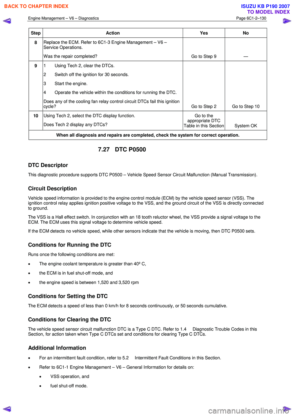
Step Action Yes No
8 Replace the ECM. Refer to 6C1-3 Engine Management – V6 –
Service Operations.
W as the repair completed? Go to Step 9 —
9 1 Using Tech 2, clear the DTCs.
2 Switch off the ignition for 30 seconds.
3 Start the engine.
4 Operate the vehicle within the conditions for running the DTC.
Does any of the cooling fan relay control circuit DTCs fail this ignition
cycle? Go to Step 2 Go to Step 10
10 Using Tech 2, select the DTC display function.
Does Tech 2 display any DTCs? Go to the
appropriate DTC
Table in this Section System OK
When all diagnosis and repairs are completed, check the system for correct operation.
7.27 DTC P0500
DTC Descriptor
This diagnostic procedure supports DTC P0500 – Vehicle Speed Sensor Circuit Malfunction (Manual Transmission).
Circuit Description
Vehicle speed information is provided to the engine control module (ECM) by the vehicle speed sensor (VSS). The
ignition control relay applies ignition positive voltage to the VSS, and the ground circuit of the VSS is directly connected
to ground.
The VSS is a Hall effect switch. In conjunction with an 18 tooth reluctor wheel, the VSS provide a signal voltage to the
ECM. The ECM uses this signal voltage to determine vehicle speed.
If the ECM detects no vehicle speed, while other sensors indicate that the vehicle is moving, then DTC P0500 sets.
Conditions for Running the DTC
Runs once the following conditions are met:
• The engine coolant temperature is greater than 40º C,
• the ECM is in fuel shut-off mode, and
• the engine speed is between 1,520 and 3,520 rpm
Conditions for Setting the DTC
The ECM detects a speed of less than 0 km/h for 8 seconds continuously, or 50 seconds cumulative.
Conditions for Clearing the DTC
The vehicle speed sensor circuit malfunction DTC is a Type C DTC. Refer to 1.4 Diagnostic Trouble Codes in this
Section, for action taken when Type C DTCs set and conditions for clearing Type C DTCs.
Additional Information
• For an intermittent fault condition, refer to 5.2 Intermittent Fault Conditions in this Section.
• Refer to 6C1-1 Engine Management – V6 – General Information for details on:
• VSS operation, and
• fuel shut-off mode.
BACK TO CHAPTER INDEX
TO MODEL INDEX
ISUZU KB P190 2007
Page 3422 of 6020
Engine Management – V6 – Diagnostics Page 6C1-2–144
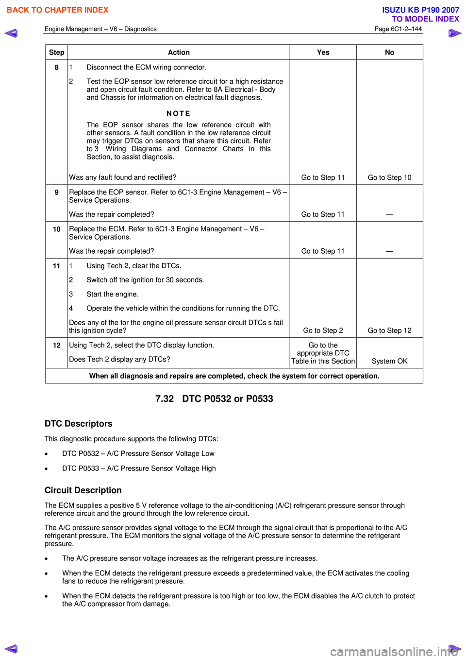
Step Action
Yes No
8 1 Disconnect the ECM wiring connector.
2 Test the EOP sensor low reference circuit for a high resistance and open circuit fault condition. Refer to 8A Electrical - Body
and Chassis for information on electrical fault diagnosis.
NOTE
The EOP sensor shares the low reference circuit with
other sensors. A fault condition in the low reference circuit
may trigger DTCs on sensors that share this circuit. Refer
to 3 W iring Diagrams and Connector Charts in this
Section, to assist diagnosis.
W as any fault found and rectified? Go to Step 11 Go to Step 10
9 Replace the EOP sensor. Refer to 6C1-3 Engine Management – V6 –
Service Operations.
W as the repair completed? Go to Step 11 —
10 Replace the ECM. Refer to 6C1-3 Engine Management – V6 –
Service Operations.
W as the repair completed? Go to Step 11 —
11 1 Using Tech 2, clear the DTCs.
2 Switch off the ignition for 30 seconds.
3 Start the engine.
4 Operate the vehicle within the conditions for running the DTC.
Does any of the for the engine oil pressure sensor circuit DTCs s fail
this ignition cycle? Go to Step 2 Go to Step 12
12 Using Tech 2, select the DTC display function.
Does Tech 2 display any DTCs? Go to the
appropriate DTC
Table in this Section System OK
When all diagnosis and repairs are completed, check the system for correct operation.
7.32 DTC P0532 or P0533
DTC Descriptors
This diagnostic procedure supports the following DTCs:
• DTC P0532 – A/C Pressure Sensor Voltage Low
• DTC P0533 – A/C Pressure Sensor Voltage High
Circuit Description
The ECM supplies a positive 5 V reference voltage to the air-conditioning (A/C) refrigerant pressure sensor through
reference circuit and the ground through the low reference circuit.
The A/C pressure sensor provides signal voltage to the ECM through the signal circuit that is proportional to the A/C
refrigerant pressure. The ECM monitors the signal voltage of the A/C pressure sensor to determine the refrigerant
pressure.
• The A/C pressure sensor voltage increases as the refrigerant pressure increases.
• W hen the ECM detects the refrigerant pressure exceeds a predetermined value, the ECM activates the cooling
fans to reduce the refrigerant pressure.
• W hen the ECM detects the refrigerant pressure is too high or too low, the ECM disables the A/C clutch to protect
the A/C compressor from damage.
BACK TO CHAPTER INDEX
TO MODEL INDEX
ISUZU KB P190 2007
Page 3502 of 6020
Engine Management – V6 – Diagnostics Page 6C1-2–224
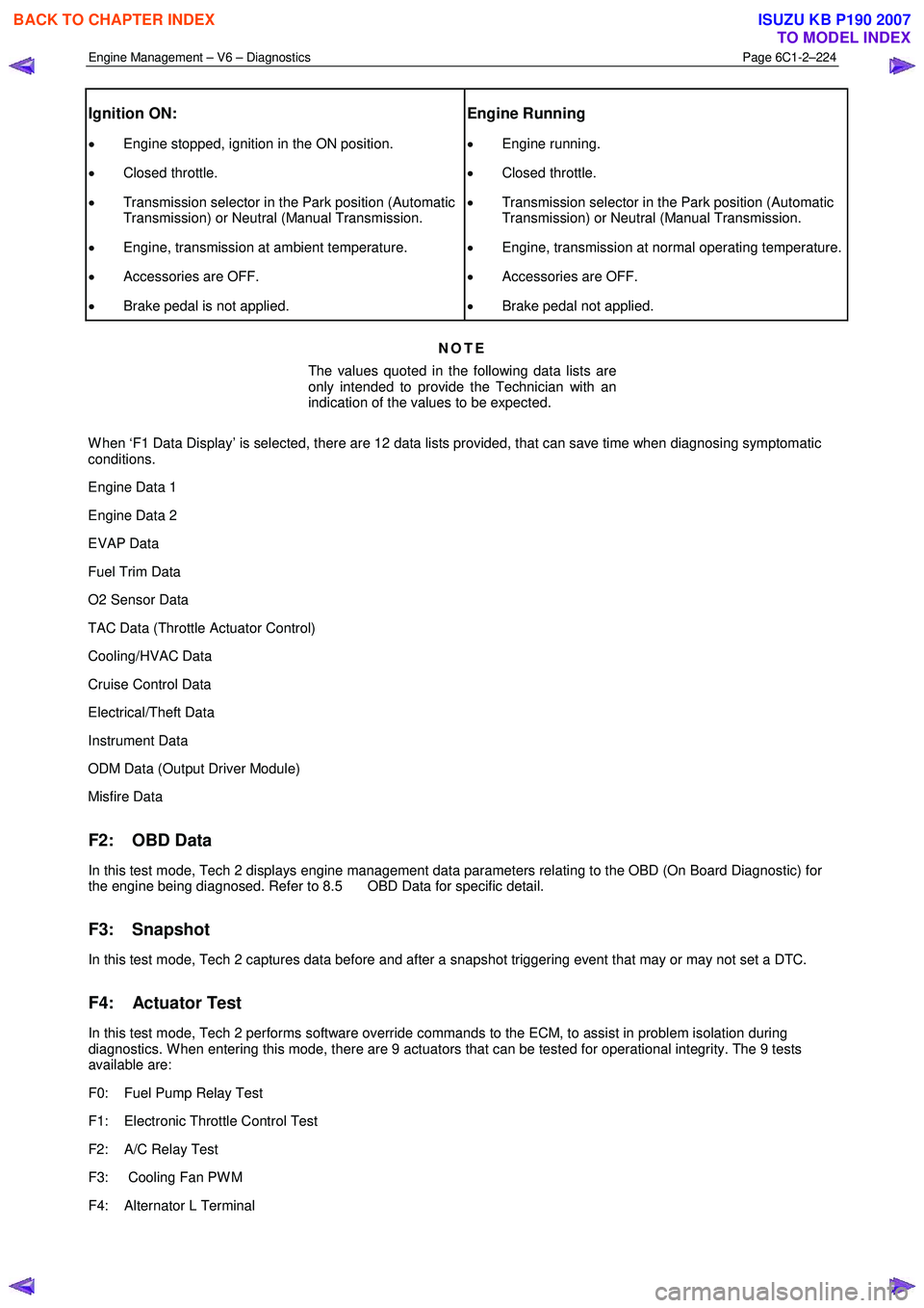
Ignition ON:
• Engine stopped, ignition in the ON position.
• Closed throttle.
• Transmission selector in the Park position (Automatic
Transmission) or Neutral (Manual Transmission.
• Engine, transmission at ambient temperature.
• Accessories are OFF.
• Brake pedal is not applied.
Engine Running
• Engine running.
• Closed throttle.
• Transmission selector in the Park position (Automatic
Transmission) or Neutral (Manual Transmission.
• Engine, transmission at normal operating temperature.
• Accessories are OFF.
• Brake pedal not applied.
NOTE
The values quoted in the following data lists are
only intended to provide the Technician with an
indication of the values to be expected.
W hen ‘F1 Data Display’ is selected, there are 12 data lists provided, that can save time when diagnosing symptomatic
conditions.
Engine Data 1
Engine Data 2
EVAP Data
Fuel Trim Data
O2 Sensor Data
TAC Data (Throttle Actuator Control)
Cooling/HVAC Data
Cruise Control Data
Electrical/Theft Data
Instrument Data
ODM Data (Output Driver Module)
Misfire Data
F2: OBD Data
In this test mode, Tech 2 displays engine management data parameters relating to the OBD (On Board Diagnostic) for
the engine being diagnosed. Refer to 8.5 OBD Data for specific detail.
F3: Snapshot
In this test mode, Tech 2 captures data before and after a snapshot triggering event that may or may not set a DTC.
F4: Actuator Test
In this test mode, Tech 2 performs software override commands to the ECM, to assist in problem isolation during
diagnostics. W hen entering this mode, there are 9 actuators that can be tested for operational integrity. The 9 tests
available are:
F0: Fuel Pump Relay Test
F1: Electronic Throttle Control Test
F2: A/C Relay Test
F3: Cooling Fan PW M
F4: Alternator L Terminal
BACK TO CHAPTER INDEX
TO MODEL INDEX
ISUZU KB P190 2007
Page 3505 of 6020
Engine Management – V6 – Diagnostics Page 6C1-2–227
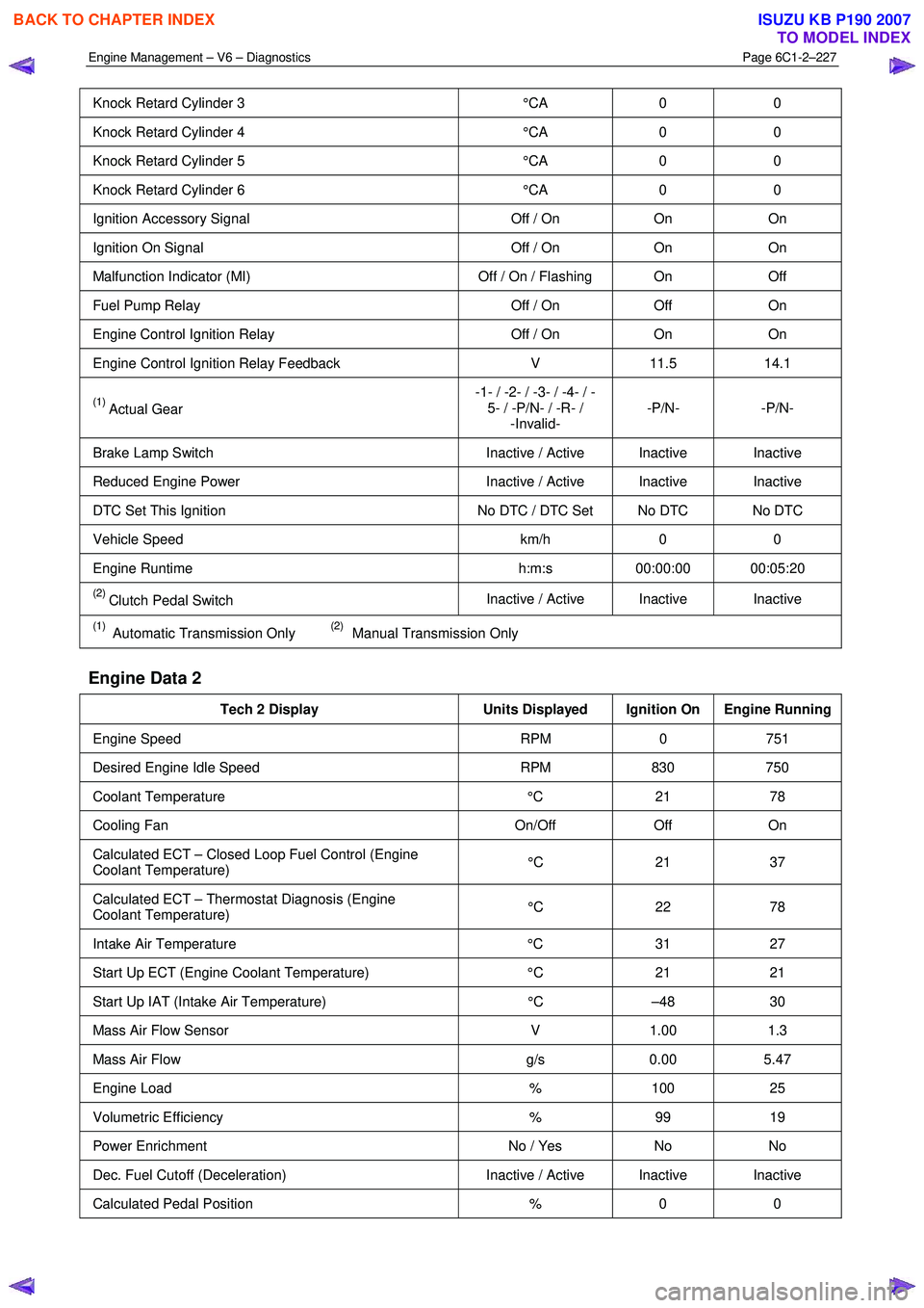
Knock Retard Cylinder 3 °CA 0 0
Knock Retard Cylinder 4 °CA 0 0
Knock Retard Cylinder 5 °CA 0 0
Knock Retard Cylinder 6 °CA 0 0
Ignition Accessory Signal Off / On On On
Ignition On Signal Off / On On On
Malfunction Indicator (MI) Off / On / Flashing On Off
Fuel Pump Relay Off / On Off On
Engine Control Ignition Relay Off / On On On
Engine Control Ignition Relay Feedback V 11.5 14.1
(1) Actual Gear -1- / -2- / -3- / -4- / -
5- / -P/N- / -R- / -Invalid- -P/N- -P/N-
Brake Lamp Switch
Inactive / Active Inactive Inactive
Reduced Engine Power Inactive / Active Inactive Inactive
DTC Set This Ignition No DTC / DTC Set No DTC No DTC
Vehicle Speed km/h 0 0
Engine Runtime h:m:s 00:00:00 00:05:20
(2) Clutch Pedal Switch Inactive / Active Inactive Inactive
(1) Automatic Transmission Only (2) Manual Transmission Only
Engine Data 2
Tech 2 Display
Units Displayed Ignition On Engine Running
Engine Speed RPM 0 751
Desired Engine Idle Speed RPM 830 750
Coolant Temperature °C 21 78
Cooling Fan On/Off Off On
Calculated ECT – Closed Loop Fuel Control (Engine
Coolant Temperature) °C 21 37
Calculated ECT – Thermostat Diagnosis (Engine
Coolant Temperature) °C 22 78
Intake Air Temperature
°C 31 27
Start Up ECT (Engine Coolant Temperature) °C 21 21
Start Up IAT (Intake Air Temperature) °C –48 30
Mass Air Flow Sensor V 1.00 1.3
Mass Air Flow g/s 0.00 5.47
Engine Load % 100 25
Volumetric Efficiency % 99 19
Power Enrichment No / Yes No No
Dec. Fuel Cutoff (Deceleration) Inactive / Active Inactive Inactive
Calculated Pedal Position % 0 0
BACK TO CHAPTER INDEX
TO MODEL INDEX
ISUZU KB P190 2007
Page 3511 of 6020
Engine Management – V6 – Diagnostics Page 6C1-2–233
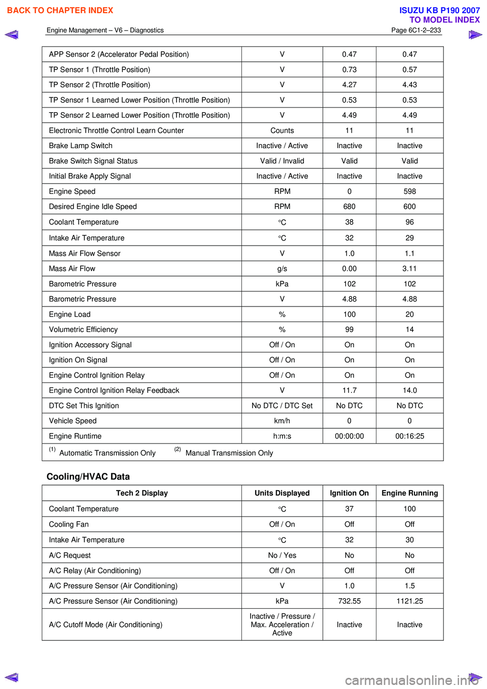
APP Sensor 2 (Accelerator Pedal Position) V 0.47 0.47
TP Sensor 1 (Throttle Position) V 0.73 0.57
TP Sensor 2 (Throttle Position) V 4.27 4.43
TP Sensor 1 Learned Lower Position (Throttle Position) V 0.53 0.53
TP Sensor 2 Learned Lower Position (Throttle Position) V 4.49 4.49
Electronic Throttle Control Learn Counter Counts 11 11
Brake Lamp Switch Inactive / Active Inactive Inactive
Brake Switch Signal Status Valid / Invalid Valid Valid
Initial Brake Apply Signal Inactive / Active Inactive Inactive
Engine Speed RPM 0 598
Desired Engine Idle Speed RPM 680 600
Coolant Temperature
°C 38 96
Intake Air Temperature
°C 32 29
Mass Air Flow Sensor
V 1.0 1.1
Mass Air Flow g/s 0.00 3.11
Barometric Pressure kPa 102 102
Barometric Pressure V 4.88 4.88
Engine Load % 100 20
Volumetric Efficiency % 99 14
Ignition Accessory Signal Off / On On On
Ignition On Signal Off / On On On
Engine Control Ignition Relay Off / On On On
Engine Control Ignition Relay Feedback V 11.7 14.0
DTC Set This Ignition No DTC / DTC Set No DTC No DTC
Vehicle Speed km/h 0 0
Engine Runtime h:m:s 00:00:00 00:16:25
(1) Automatic Transmission Only (2) Manual Transmission Only
Cooling/HVAC Data
Tech 2 Display Units Displayed Ignition On Engine Running
Coolant Temperature
°C 37 100
Cooling Fan
Off / On Off Off
Intake Air Temperature
°C 32 30
A/C Request
No / Yes No No
A/C Relay (Air Conditioning) Off / On Off Off
A/C Pressure Sensor (Air Conditioning) V 1.0 1.5
A/C Pressure Sensor (Air Conditioning) kPa 732.55 1121.25
A/C Cutoff Mode (Air Conditioning) Inactive / Pressure /
Max. Acceleration / Active Inactive Inactive
BACK TO CHAPTER INDEX
TO MODEL INDEX
ISUZU KB P190 2007
Page 3518 of 6020

Engine Management – V6 – Diagnostics Page 6C1-2–240
Cruise Control Switch: This parameter displays the state of the cruise control on/off switch input to the control module.
Cruise Control Disengagement Reason: The parameter displays which of a possible 28 causes for the cruise control
to disengage.
CC Disengagement 1 – 8 History (Cruise Control): The parameter displays the last 8 cruise control disengages in
order from 1 to 8, with 8 being the most recent. There are about 28 possible causes for the cruise control to disengage.
Cruise Resume/Acceleration Switch: This parameter displays the state of the cruise control resume/accel switch
position input to the ECM.
Cruise Set / Coast Switch: This parameter displays the state of the cruise controls set/decel. switch position input to
the ECM.
Cycles of Misfire: This parameter displays the number of misfire tests during 200 engine revolutions.
Cylinder 1 – 6 Injector Circuit Status: This parameter displays the state of the fuel injector control circuit. The
parameter displays ‘Fault’ if the fuel injector control circuit is open, shorted to ground, or shorted to voltage. This
parameter displays ‘Undefined Status’ until the control circuit has been commanded ‘On’.
Dec. Fuel Cutoff (Deceleration): This parameter displays the status of the ECM operating mode, used to turn off the
fuel injectors and the evaporative emission (EVAP) canister purge valve during certain deceleration conditions.
Desired Engine Idle Speed: This parameter displays the desired engine idle speed as commanded by the ECM.
Desired Throttle Position: This parameter displays the desired throttle position (TP) angle commanded by the ECM.
Distance Since DTC Cleared: This parameter displays the distance (km) travelled since any diagnostic trouble code
(DTC) has been cleared from the ECM memory.
DTC Set This Ignition: This parameter displays Yes if a DTC set on the current ignition cycle.
ECM Immobilized: This parameter displays ‘Yes’ when an internal control module reset occurs. Tech 2 will display ‘No’
under normal operating conditions.
Electronic Throttle Control Learn Counter: W hen the ECM performs a throttle body relearn procedure, the throttle
plate is commanded to move from the rest position (7% open) to full closed (0%), then to around 10% open.
At the start of this procedure, the Tech 2 ‘TAC Learn Counter’ parameter should display 0, then count up to 11 after the
procedure is completed. If the counter did not start at 0 or if the counter did not end at 11, a fault has occurred and a
DTC should set.
Engine Control Ignition Relay: This parameter displays the state of the control circuit for control module power relay
as commanded by the ECM.
Engine Control Ignition Relay Feedback: This parameter displays the voltage available at the engine control ignition
relay pin of the control module.
Engine Load: This parameter displays the calculated engine load in percent based on inputs to the control module from
various engine sensors.
Engine Oil Life Remaining: This parameter displays the percentage of engine oil life remaining. The controller
calculates the engine oil life by monitoring engine load, collant temperature and engine speed.
Engine Oil Pressure: This parameter displays the oil pressure in kPa from the ECM, developed from the engine oil
pressure (EOP) sensor input.
Engine Oil Pressure Sensor: This parameter displays ‘High’ if the engine oil pressure is within the correct range. If the
ECM detects that the engine oil pressure is not within the correct range, Tech 2 will display ‘Low’.
Engine Runtime: This parameter displays the time elapsed since the engine was started.
Engine Speed: This parameter displays the speed of the engine crankshaft rotation from information received from the
CKP sensor. If there is a CKP sensor DTC, the ECM calculates the engine speed from one of the camshaft position
(CMP) sensors.
EVAP Purge Solenoid (Evaporative Emission): This parameter displays the on-time or duty cycle of the EVAP
canister purge solenoid commanded by the ECM. Zero percent indicates no purge. One hundred percent indicates full
purge.
EVAP Purge Solenoid Valve Circuit Status (Evaporative Emission): This parameter displays the state of the EVAP
purge solenoid control circuit. The parameter displays ‘Fault’ if the EVAP purge solenoid control circuit is open, shorted
to ground, or shorted to voltage. The parameter displays ‘Undefined Status’ until the circuit has been established as
‘OK’.
Cooling Fan Relay: This parameter displays the control module commanded state of the fan relay control circuit.
BACK TO CHAPTER INDEX
TO MODEL INDEX
ISUZU KB P190 2007
Page 3519 of 6020
Engine Management – V6 – Diagnostics Page 6C1-2–241
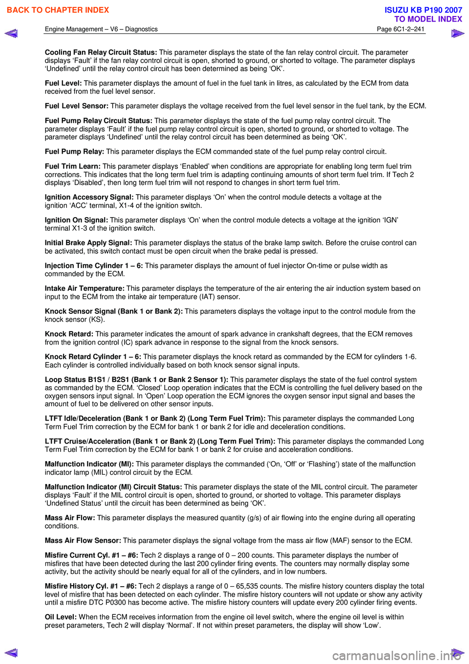
Cooling Fan Relay Circuit Status: This parameter displays the state of the fan relay control circuit. The parameter
displays ‘Fault’ if the fan relay control circuit is open, shorted to ground, or shorted to voltage. The parameter displays
‘Undefined’ until the relay control circuit has been determined as being ‘OK’.
Fuel Level: This parameter displays the amount of fuel in the fuel tank in litres, as calculated by the ECM from data
received from the fuel level sensor.
Fuel Level Sensor: This parameter displays the voltage received from the fuel level sensor in the fuel tank, by the ECM.
Fuel Pump Relay Circuit Status: This parameter displays the state of the fuel pump relay control circuit. The
parameter displays ‘Fault’ if the fuel pump relay control circuit is open, shorted to ground, or shorted to voltage. The
parameter displays ‘Undefined’ until the relay control circuit has been determined as being ‘OK’.
Fuel Pump Relay: This parameter displays the ECM commanded state of the fuel pump relay control circuit.
Fuel Trim Learn: This parameter displays ‘Enabled’ when conditions are appropriate for enabling long term fuel trim
corrections. This indicates that the long term fuel trim is adapting continuing amounts of short term fuel trim. If Tech 2
displays ‘Disabled’, then long term fuel trim will not respond to changes in short term fuel trim.
Ignition Accessory Signal: This parameter displays ‘On’ when the control module detects a voltage at the
ignition ‘ACC’ terminal, X1-4 of the ignition switch.
Ignition On Signal: This parameter displays ‘On’ when the control module detects a voltage at the ignition ‘IGN’
terminal X1-3 of the ignition switch.
Initial Brake Apply Signal: This parameter displays the status of the brake lamp switch. Before the cruise control can
be activated, this switch contact must be open circuit when the brake pedal is pressed.
Injection Time Cylinder 1 – 6: This parameter displays the amount of fuel injector On-time or pulse width as
commanded by the ECM.
Intake Air Temperature: This parameter displays the temperature of the air entering the air induction system based on
input to the ECM from the intake air temperature (IAT) sensor.
Knock Sensor Signal (Bank 1 or Bank 2): This parameters displays the voltage input to the control module from the
knock sensor (KS).
Knock Retard: This parameter indicates the amount of spark advance in crankshaft degrees, that the ECM removes
from the ignition control (IC) spark advance in response to the signal from the knock sensors.
Knock Retard Cylinder 1 – 6: This parameter displays the knock retard as commanded by the ECM for cylinders 1-6.
Each cylinder is controlled individually based on both knock sensor signal inputs.
Loop Status B1S1 / B2S1 (Bank 1 or Bank 2 Sensor 1): This parameter displays the state of the fuel control system
as commanded by the ECM. ‘Closed’ Loop operation indicates that the ECM is controlling the fuel delivery based on the
oxygen sensors input signal. In ‘Open’ Loop operation the ECM ignores the oxygen sensor input signal and bases the
amount of fuel to be delivered on other sensor inputs.
LTFT Idle/Deceleration (Bank 1 or Bank 2) (Long Term Fuel Trim): This parameter displays the commanded Long
Term Fuel Trim correction by the ECM for bank 1 or bank 2 for idle and deceleration conditions.
LTFT Cruise/Acceleration (Bank 1 or Bank 2) (Long Term Fuel Trim): This parameter displays the commanded Long
Term Fuel Trim correction by the ECM for bank 1 or bank 2 for cruise and acceleration conditions.
Malfunction Indicator (MI): This parameter displays the commanded (‘On, ‘Off’ or ‘Flashing’) state of the malfunction
indicator lamp (MIL) control circuit by the ECM.
Malfunction Indicator (MI) Circuit Status: This parameter displays the state of the MIL control circuit. The parameter
displays ‘Fault’ if the MIL control circuit is open, shorted to ground, or shorted to voltage. This parameter displays
‘Undefined Status’ until the circuit has been determined as being ‘OK’.
Mass Air Flow: This parameter displays the measured quantity (g/s) of air flowing into the engine during all operating
conditions.
Mass Air Flow Sensor: This parameter displays the signal voltage from the mass air flow (MAF) sensor to the ECM.
Misfire Current Cyl. #1 – #6: Tech 2 displays a range of 0 – 200 counts. This parameter displays the number of
misfires that have been detected during the last 200 cylinder firing events. The counters may normally display some
activity, but the activity should be nearly equal for all of the cylinders, and in low numbers.
Misfire History Cyl. #1 – #6: Tech 2 displays a range of 0 – 65,535 counts. The misfire history counters display the total
level of misfire that has been detected on each cylinder. The misfire history counters will not update or show any activity
until a misfire DTC P0300 has become active. The misfire history counters will update every 200 cylinder firing events.
Oil Level: W hen the ECM receives information from the engine oil level switch, where the engine oil level is within
preset parameters, Tech 2 will display ‘Normal’. If not within preset parameters, the display will show ‘Low’.
BACK TO CHAPTER INDEX
TO MODEL INDEX
ISUZU KB P190 2007
Page 3522 of 6020
Engine Management – V6 – Diagnostics Page 6C1-2–244
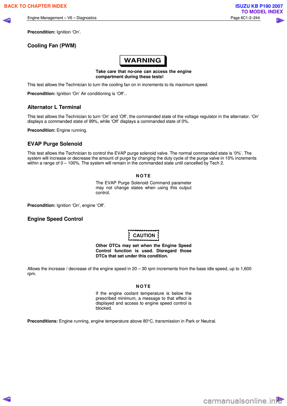
Precondition: Ignition ‘On’.
Cooling Fan (PWM)
Take care that no-one can access the engine
compartment during these tests!
This test allows the Technician to turn the cooling fan on in increments to its maximum speed.
Precondition: Ignition ‘On’ Air conditioning is ‘Off’..
Alternator L Terminal
This test allows the Technician to turn ‘On’ and ‘Off’, the commanded state of the voltage regulator in the alternator. ‘On’
displays a commanded state of 99%, while ‘Off’ displays a commanded state of 0%.
Precondition: Engine running.
EVAP Purge Solenoid
This test allows the Technician to control the EVAP purge solenoid valve. The normal commanded state is ‘0%’. The
system will increase or decrease the amount of purge by changing the duty cycle of the purge valve in 10% increments
within a range of 0 – 100%. The system will remain in the commanded state until cancelled by Tech 2.
NOTE
The EVAP Purge Solenoid Command parameter
may not change states when using this output
control.
Precondition: Ignition ‘On’, engine ‘Off’.
Engine Speed Control
Other DTCs may set when the Engine Speed
Control function is used. Disregard those
DTCs that set under this condition.
Allows the increase / decrease of the engine speed in 20 – 30 rpm increments from the base idle speed, up to 1,600
rpm.
NOTE
If the engine coolant temperature is below the
prescribed minimum, a message to that effect is
displayed and access to engine speed control is
blocked.
Preconditions: Engine running, engine temperature above 80 °C, transmission in Park or Neutral.
BACK TO CHAPTER INDEX
TO MODEL INDEX
ISUZU KB P190 2007