2007 ISUZU KB P190 cooling
[x] Cancel search: coolingPage 3821 of 6020
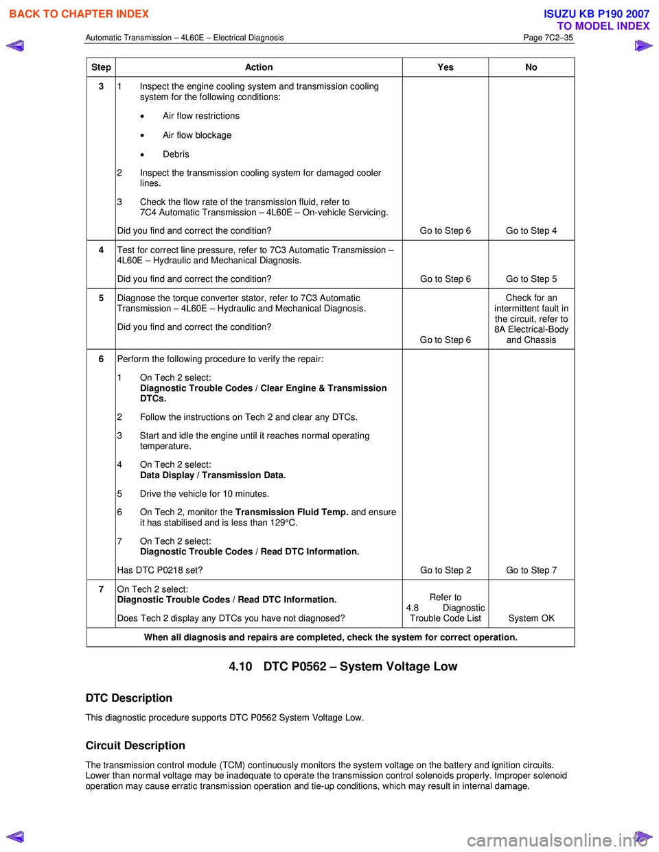
Automatic Transmission – 4L60E – Electrical Diagnosis Page 7C2–35
Step Action Yes No
3 1 Inspect the engine cooling system and transmission cooling
system for the following conditions:
• Air flow restrictions
• Air flow blockage
• Debris
2 Inspect the transmission cooling system for damaged cooler lines.
3 Check the flow rate of the transmission fluid, refer to 7C4 Automatic Transmission – 4L60E – On-vehicle Servicing.
Did you find and correct the condition? Go to Step 6 Go to Step 4
4 Test for correct line pressure, refer to 7C3 Automatic Transmission –
4L60E – Hydraulic and Mechanical Diagnosis.
Did you find and correct the condition? Go to Step 6 Go to Step 5
5 Diagnose the torque converter stator, refer to 7C3 Automatic
Transmission – 4L60E – Hydraulic and Mechanical Diagnosis.
Did you find and correct the condition? Go to Step 6 Check for an
intermittent fault in the circuit, refer to
8A Electrical-Body
and Chassis
6 Perform the following procedure to verify the repair:
1 On Tech 2 select: Diagnostic Trouble Codes / Clear Engine & Transmission
DTCs.
2 Follow the instructions on Tech 2 and clear any DTCs.
3 Start and idle the engine until it reaches normal operating temperature.
4 On Tech 2 select: Data Display / Transmission Data.
5 Drive the vehicle for 10 minutes.
6 On Tech 2, monitor the Transmission Fluid Temp. and ensure
it has stabilised and is less than 129°C.
7 On Tech 2 select:
Diagnostic Trouble Codes / Read DTC Information.
Has DTC P0218 set? Go to Step 2 Go to Step 7
7 On Tech 2 select:
Diagnostic Trouble Codes / Read DTC Information.
Does Tech 2 display any DTCs you have not diagnosed? Refer to
4.8 Diagnostic Trouble Code List System OK
When all diagnosis and repairs are completed, check the
system for correct operation.
4.10 DTC P0562 – System Voltage Low
DTC Description
This diagnostic procedure supports DTC P0562 System Voltage Low.
Circuit Description
The transmission control module (TCM) continuously monitors the system voltage on the battery and ignition circuits.
Lower than normal voltage may be inadequate to operate the transmission control solenoids properly. Improper solenoid
operation may cause erratic transmission operation and tie-up conditions, which may result in internal damage.
BACK TO CHAPTER INDEX
TO MODEL INDEX
ISUZU KB P190 2007
Page 3832 of 6020
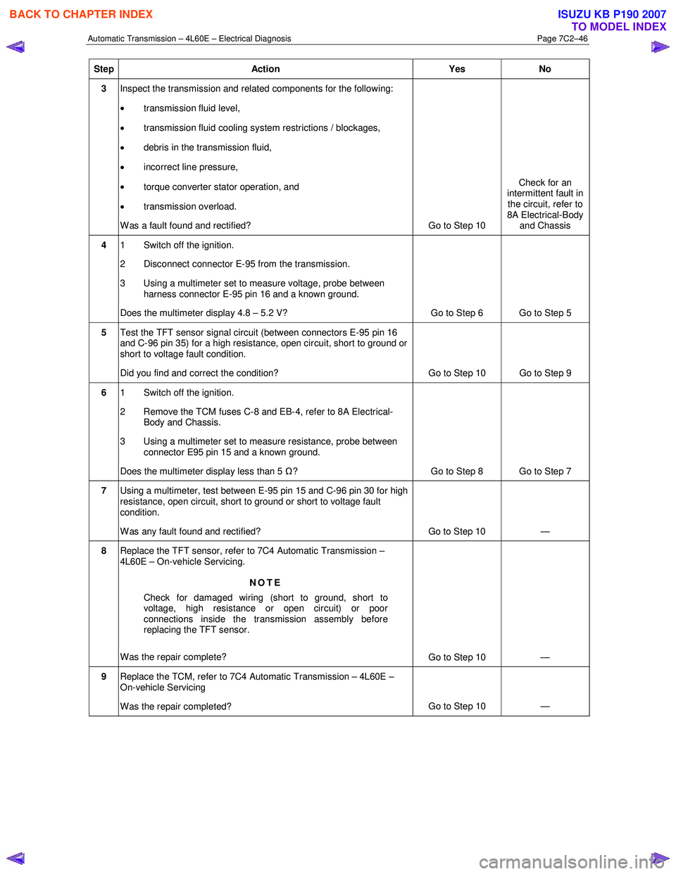
Automatic Transmission – 4L60E – Electrical Diagnosis Page 7C2–46
Step Action Yes No
3 Inspect the transmission and related components for the following:
• transmission fluid level,
• transmission fluid cooling system restrictions / blockages,
• debris in the transmission fluid,
• incorrect line pressure,
• torque converter stator operation, and
• transmission overload.
W as a fault found and rectified? Go to Step 10 Check for an
intermittent fault in
the circuit, refer to
8A Electrical-Body and Chassis
4 1 Switch off the ignition.
2 Disconnect connector E-95 from the transmission.
3 Using a multimeter set to measure voltage, probe between harness connector E-95 pin 16 and a known ground.
Does the multimeter display 4.8 – 5.2 V? Go to Step 6 Go to Step 5
5 Test the TFT sensor signal circuit (between connectors E-95 pin 16
and C-96 pin 35) for a high resistance, open circuit, short to ground or
short to voltage fault condition.
Did you find and correct the condition? Go to Step 10 Go to Step 9
6 1 Switch off the ignition.
2 Remove the TCM fuses C-8 and EB-4, refer to 8A Electrical- Body and Chassis.
3 Using a multimeter set to measure resistance, probe between connector E95 pin 15 and a known ground.
Does the multimeter display less than 5 Ω? Go to Step 8 Go to Step 7
7 Using a multimeter, test between E-95 pin 15 and C-96 pin 30 for high
resistance, open circuit, short to ground or short to voltage fault
condition.
W as any fault found and rectified? Go to Step 10 —
8 Replace the TFT sensor, refer to 7C4 Automatic Transmission –
4L60E – On-vehicle Servicing.
NOTE
Check for damaged wiring (short to ground, short to
voltage, high resistance or open circuit) or poor
connections inside the transmission assembly before
replacing the TFT sensor.
Was the repair complete? Go to Step 10 —
9 Replace the TCM, refer to 7C4 Automatic Transmission – 4L60E –
On-vehicle Servicing
Was the repair completed? Go to Step 10
—
BACK TO CHAPTER INDEX
TO MODEL INDEX
ISUZU KB P190 2007
Page 4243 of 6020
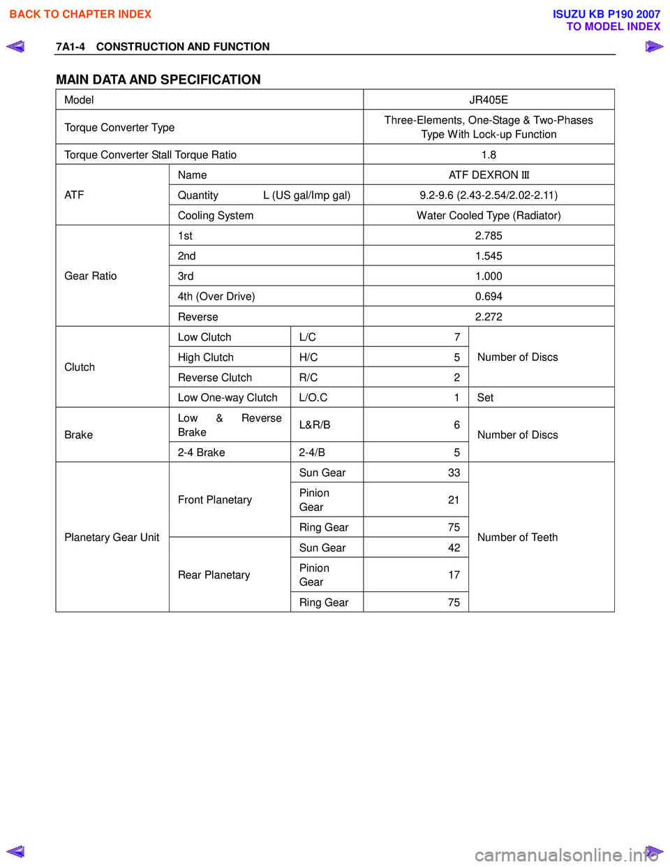
7A1-4 CONSTRUCTION AND FUNCTION
MAIN DATA AND SPECIFICATION
Model JR405E
Torque Converter Type Three-Elements, One-Stage & Two-Phases
Type W ith Lock-up Function
Torque Converter Stall Torque Ratio 1.8
Name ATF DEXRON III
Quantity L (US gal/Imp gal) 9.2-9.6 (2.43-2.54/2.02-2.11) AT F
Cooling System Water Cooled Type (Radiator)
1st 2.785
2nd 1.545
3rd 1.000
4th (Over Drive) 0.694
Gear Ratio
Reverse 2.272
Low Clutch L/C 7
High Clutch H/C 5
Reverse Clutch R/C 2Number of Discs Clutch
Low One-way Clutch L/O.C 1 Set
Low & Reverse
Brake L&R/B 6
Brake
2-4 Brake 2-4/B 5 Number of Discs
Sun Gear
33
Pinion
Gear 21Front Planetary
Ring Gear 75
Sun Gear 42
Pinion
Gear 17
Planetary Gear Unit
Rear Planetary Ring Gear 75 Number of Teeth
BACK TO CHAPTER INDEX
TO MODEL INDEX
ISUZU KB P190 2007
Page 4286 of 6020
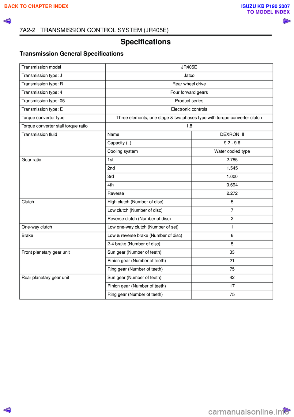
7A2-2 TRANSMISSION CONTROL SYSTEM (JR405E)
Specifications
Transmission General Specifications
Transmission modelJR405E
Transmission type: J Jatco
Transmission type: R Rear wheel drive
Transmission type: 4 Four forward gears
Transmission type: 05 Product series
Transmission type: E Electronic controls
Torque converter type Three elements, one stage & two phases type with torque converter clutch
Torque converter stall torque ratio 1.8
Transmission fluid Name DEXRON III
Capacity (L) 9.2 - 9.6
Cooling system Water cooled type
Gear ratio 1st 2.785
2nd 1.545
3rd 1.000
4th 0.694
Reverse 2.272
Clutch High clutch (Number of disc) 5
Low clutch (Number of disc) 7
Reverse clutch (Number of disc) 2
One-way clutch Low one-way clutch (Number of set) 1
Brake Low & reverse brake (Number of disc) 6
2-4 brake (Number of disc) 5
Front planetary gear unit Sun gear (Number of teeth) 33
Pinion gear (Number of teeth) 21
Ring gear (Number of teeth) 75
Rear planetary gear unit Sun gear (Number of teeth) 42
Pinion gear (Number of teeth) 17
Ring gear (Number of teeth) 75
BACK TO CHAPTER INDEX
TO MODEL INDEX
ISUZU KB P190 2007
Page 4473 of 6020
ON-VEHICLE SERVICE (JR405E) 7A3-19
Install or Connect
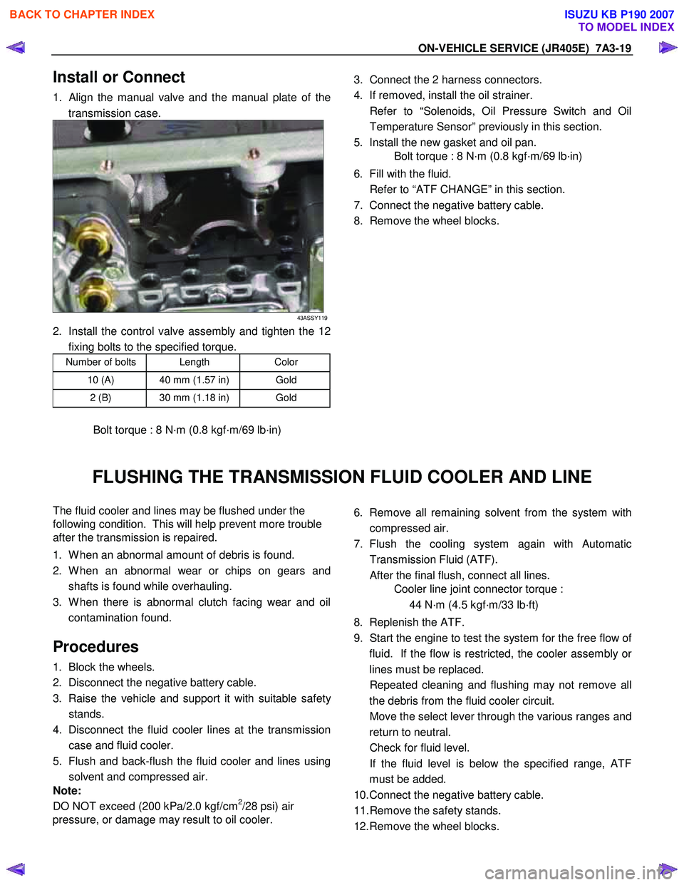
1. Align the manual valve and the manual plate of the
transmission case.
43ASSY119
2. Install the control valve assembly and tighten the 12 fixing bolts to the specified torque.
Number of bolts Length Color
10 (A) 40 mm (1.57 in) Gold
2 (B) 30 mm (1.18 in) Gold
Bolt torque : 8 N·m (0.8 kgf·m/69 lb·in)
3. Connect the 2 harness connectors.
4. If removed, install the oil strainer.
Refer to “Solenoids, Oil Pressure Switch and Oil Temperature Sensor” previously in this section.
5. Install the new gasket and oil pan.
Bolt torque : 8 N·m (0.8 kgf·m/69 lb·in)
6. Fill with the fluid.
Refer to “ATF CHANGE” in this section.
7. Connect the negative battery cable.
8. Remove the wheel blocks.
FLUSHING THE TRANSMISSION FLUID COOLER AND LINE
The fluid cooler and lines may be flushed under the
following condition. This will help prevent more trouble
after the transmission is repaired.
1. W hen an abnormal amount of debris is found.
2. W hen an abnormal wear or chips on gears and shafts is found while overhauling.
3. W hen there is abnormal clutch facing wear and oil contamination found.
Procedures
1. Block the wheels.
2. Disconnect the negative battery cable.
3. Raise the vehicle and support it with suitable safet
y
stands.
4. Disconnect the fluid cooler lines at the transmission case and fluid cooler.
5. Flush and back-flush the fluid cooler and lines using solvent and compressed air.
Note:
DO NOT exceed (200 kPa/2.0 kgf/cm
2/28 psi) air
pressure, or damage may result to oil cooler.
6. Remove all remaining solvent from the system with
compressed air.
7. Flush the cooling system again with Automatic Transmission Fluid (ATF).
After the final flush, connect all lines.
Cooler line joint connector torque :
44 N·m (4.5 kgf·m/33 lb·ft)
8. Replenish the ATF.
9. Start the engine to test the system for the free flow o
f
fluid. If the flow is restricted, the cooler assembly o
r
lines must be replaced.
Repeated cleaning and flushing may not remove all the debris from the fluid cooler circuit.
Move the select lever through the various ranges and return to neutral.
Check for fluid level.
If the fluid level is below the specified range, ATF must be added.
10. Connect the negative battery cable.
11. Remove the safety stands.
12. Remove the wheel blocks.
BACK TO CHAPTER INDEX
TO MODEL INDEX
ISUZU KB P190 2007
Page 4475 of 6020
ON-VEHICLE SERVICE (JR405E) 7A3-21
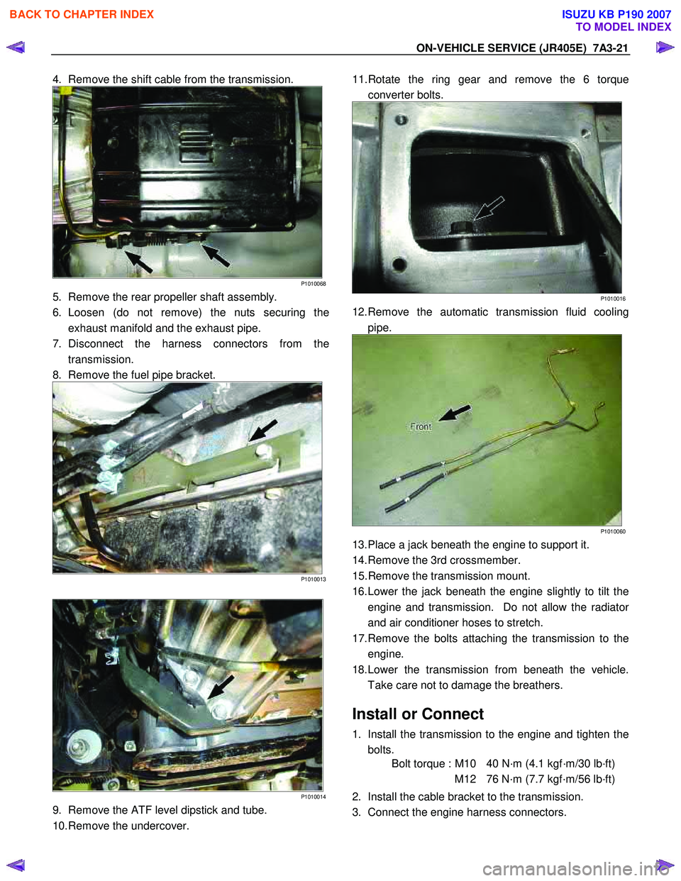
4. Remove the shift cable from the transmission.
P1010068
5. Remove the rear propeller shaft assembly.
6. Loosen (do not remove) the nuts securing the exhaust manifold and the exhaust pipe.
7. Disconnect the harness connectors from the transmission.
8. Remove the fuel pipe bracket.
P1010013
P1010014
9. Remove the ATF level dipstick and tube.
10. Remove the undercover.
11. Rotate the ring gear and remove the 6 torque
converter bolts.
P1010016
12. Remove the automatic transmission fluid cooling pipe.
P1010060
13. Place a jack beneath the engine to support it.
14. Remove the 3rd crossmember.
15. Remove the transmission mount.
16. Lower the jack beneath the engine slightly to tilt the engine and transmission. Do not allow the radiato
r
and air conditioner hoses to stretch.
17. Remove the bolts attaching the transmission to the engine.
18. Lower the transmission from beneath the vehicle. Take care not to damage the breathers.
Install or Connect
1. Install the transmission to the engine and tighten the bolts.
Bolt torque : M10 40 N·m (4.1 kgf·m/30 lb·ft)
M12 76 N·m (7.7 kgf·m/56 lb·ft)
2. Install the cable bracket to the transmission.
3. Connect the engine harness connectors.
BACK TO CHAPTER INDEX
TO MODEL INDEX
ISUZU KB P190 2007
Page 4476 of 6020
7A3-22 ON-VEHICLE SERVICE (JR405E)
4. Install the transmission mount.
Bolt torque (rubber to transmission) :
50N·m (5.1 kgf·m/37 lb·ft)
Nut torque (rubber to crossmember) :
52N·m (5.3 kgf·m/38 lb·ft)
5. Install the 3rd crossmember.
Bolt and Nut torque : 67 N·m (6.8 kgf·m/49 lb·ft)
Bolt torque : 50 N·m (5.1 kgf·m/37 lb·ft)
6. Install the automatic transmission fluid cooling pipe.
7. Install the torque converter bolts.
Bolt torque : 29 N·m (3.0 kgf·m/22 lb·ft)
8. Install the undercover.
Bolt torque : 9 N·m (0.9 kgf·m/78 lb·in)
9. Install the ATF level dipstick and tube.
10. Install the fuel hose bracket.
Bolt torque : 10 N·m (1.0 kgf·m/87 lb·in)
11. Tighten the nuts securing the exhaust manifold and the exhaust pipe.
Bolt torque : 43 N·m (4.4 kgf·m/32 lb·ft)
12. Install the rear propeller shaft assembly.
Flange bolt torque : 59 N·m (6.0 kgf·m/43 lb·ft)
Center bearing bracket bolt torque :
69 N·m (7.0 kgf·m/51 lb·ft)
13. Install the shift cable.
14. Connect the negative battery cable.
15. Remove the safety stands.
16. Remove the wheels blocks.
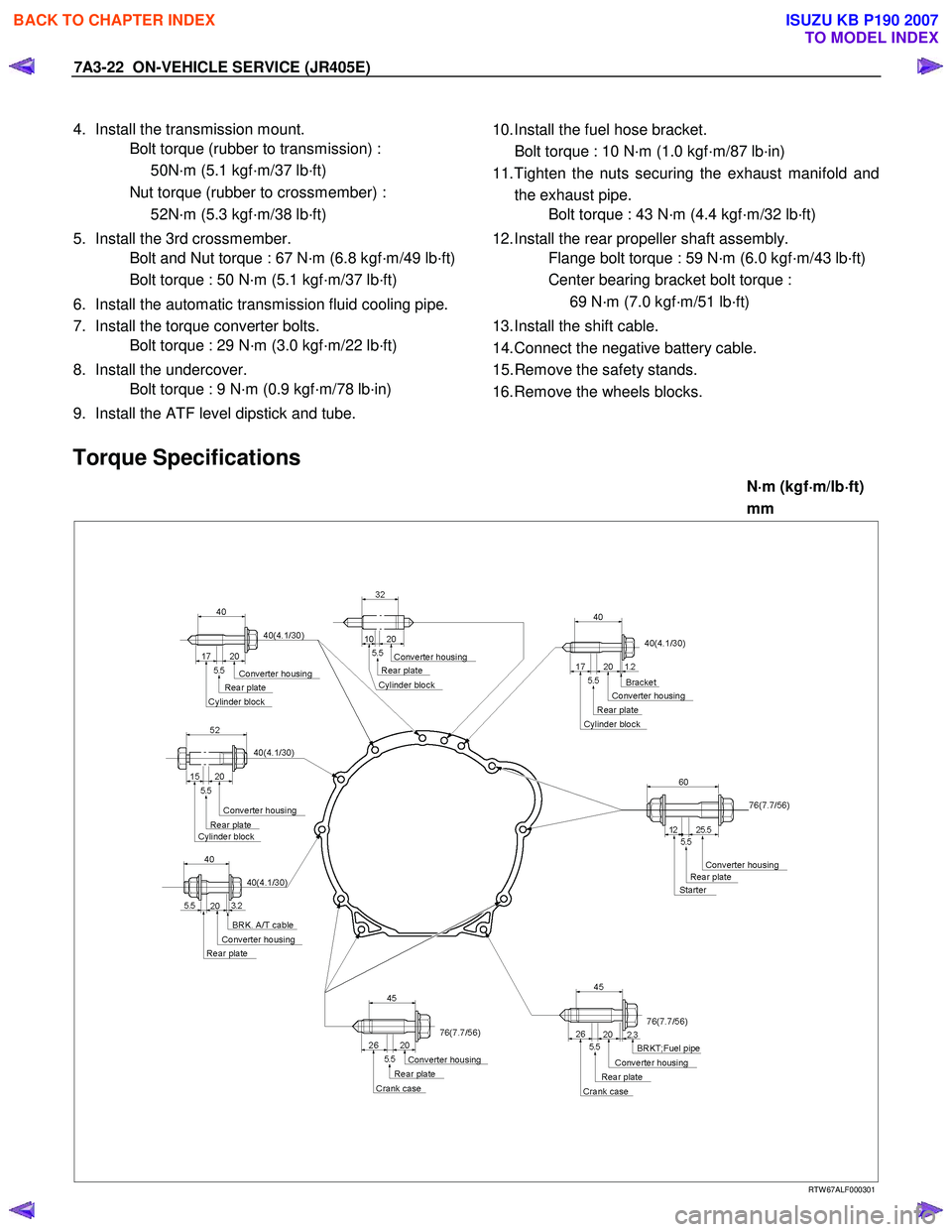
Torque Specifications
N ⋅
⋅⋅
⋅
m (kgf ⋅
⋅⋅
⋅
m/lb ⋅
⋅⋅
⋅
ft)
mm
RTW 67ALF000301
BACK TO CHAPTER INDEX
TO MODEL INDEX
ISUZU KB P190 2007