2007 ISUZU KB P190 FLASH CODE
[x] Cancel search: FLASH CODEPage 4001 of 6020
TRANSMISSION CONTROL SYSTEM (AW30–40LE) 7A2-35
Clear DTC
NOTE: If you clear the DTC (Diagnostic Trouble
Codes) you will not be able to read any codes recorded
during the last occurrence.
NOTE: To use the DTC again to identify a problem, you
will need to reproduce the fault or the problem. This
may require a new test drive or just turning the ignition
on (this depends on the nature of the fault).
1. IF you have a Tech 2:
1. Connect the Tech 2 and perform the Tech 2
Operating.
2. Push “F1: Clear DTC Information” in the
Application Menu and answer “Yes” to the
question “Do you want to clear DTC's?”
a. W hen a malfunction still exists and the Tech 2 displays “AW 30-40 CODES NOT
CLEARED”. This means that the problem is
still there or that the recovery was not done.
Please go to DTC Check.
b. W hen a malfunction has been repaired and the recovery is done the Tech 2 displays
“AW 30-40LE CODES CLEARED”.
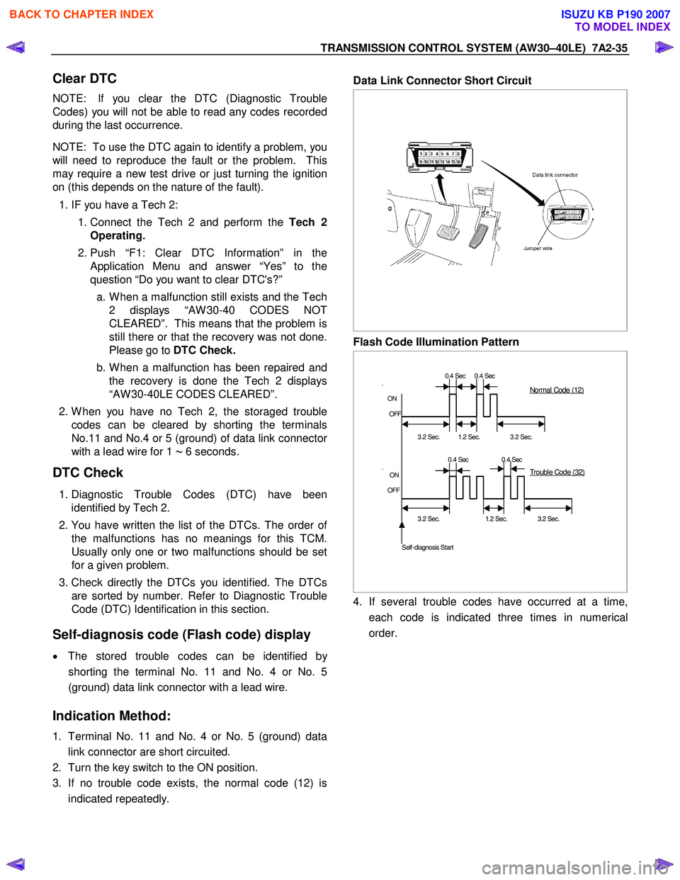
2. W hen you have no Tech 2, the storaged trouble
codes can be cleared by shorting the terminals
No.11 and No.4 or 5 (ground) of data link connecto
r
with a lead wire for 1 ∼ 6 seconds.
DTC Check
1. Diagnostic Trouble Codes (DTC) have been
identified by Tech 2.
2. You have written the list of the DTCs. The order o
f
the malfunctions has no meanings for this TCM.
Usually only one or two malfunctions should be set
for a given problem.
3. Check directly the DTCs you identified. The DTCs
are sorted by number. Refer to Diagnostic Trouble
Code (DTC) Identification in this section.
Self-diagnosis code (Flash code) display
• The stored trouble codes can be identified by
shorting the terminal No. 11 and No. 4 or No. 5
(ground) data link connector with a lead wire.
Indication Method:
1. Terminal No. 11 and No. 4 or No. 5 (ground) data
link connector are short circuited.
2. Turn the key switch to the ON position.
3. If no trouble code exists, the normal code (12) is
indicated repeatedly.
Data Link Connector Short Circuit
Flash Code Illumination Pattern
0.4 Sec 0.4 Sec
.
ON
OFF
3.2 Sec.
1.2 Sec.
3.2 Sec.
0.4 Sec 0.4 Sec
.
ON
OFF
3.2 Sec. 1.2 Sec. 3.2 Sec.
Self-diagnosis Start
Normal Code (12)
Trouble Code (32)
4. If several trouble codes have occurred at a time,
each code is indicated three times in numerical
order.
BACK TO CHAPTER INDEX
TO MODEL INDEX
ISUZU KB P190 2007
Page 4004 of 6020
7A2-38 TRANSMISSION CONTROL SYSTEM (AW30–40LE)
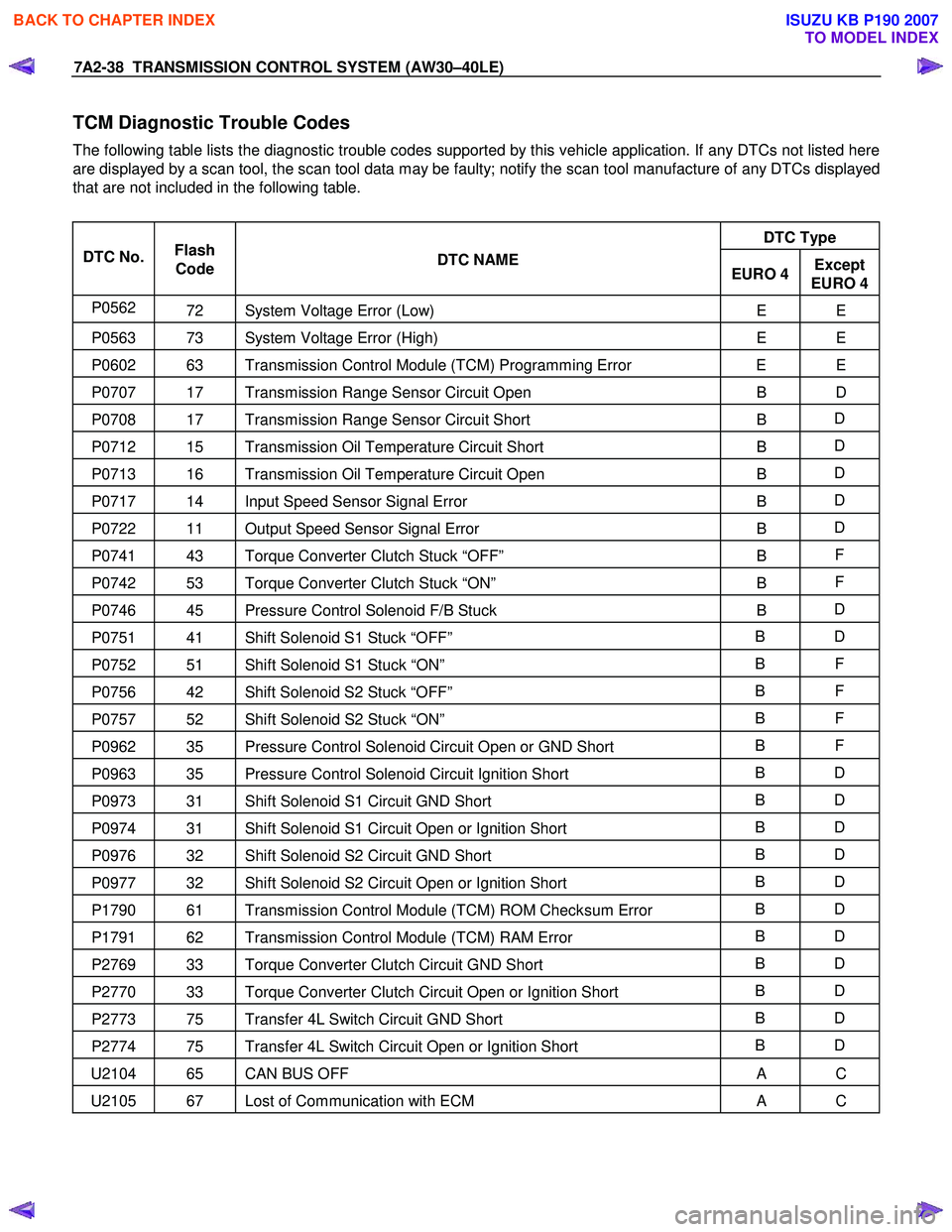
TCM Diagnostic Trouble Codes
The following table lists the diagnostic trouble codes supported by this vehicle application. If any DTCs not listed here
are displayed by a scan tool, the scan tool data may be faulty; notify the scan tool manufacture of any DTCs displayed
that are not included in the following table.
DTC Type
DTC No. Flash
Code DTC NAME
EURO 4Except
EURO 4
P0562 72 System Voltage Error (Low) E E
P0563 73 System Voltage Error (High) E E
P0602 63 Transmission Control Module (TCM) Programming Error E E
P0707 17 Transmission Range Sensor Circuit Open B D
P0708 17 Transmission Range Sensor Circuit Short B D
P0712 15 Transmission Oil Temperature Circuit Short
B D
P0713 16 Transmission Oil Temperature Circuit Open
B D
P0717 14 Input Speed Sensor Signal Error
B D
P0722 11 Output Speed Sensor Signal Error
B D
P0741 43 Torque Converter Clutch Stuck “OFF”
B F
P0742 53 Torque Converter Clutch Stuck “ON”
B F
P0746 45 Pressure Control Solenoid F/B Stuck
B D
P0751 41 Shift Solenoid S1 Stuck “OFF” B D
P0752 51 Shift Solenoid S1 Stuck “ON” B F
P0756 42 Shift Solenoid S2 Stuck “OFF” B F
P0757 52 Shift Solenoid S2 Stuck “ON” B F
P0962 35 Pressure Control Solenoid Circuit Open or GND Short B F
P0963 35 Pressure Control Solenoid Circuit Ignition Short B D
P0973 31 Shift Solenoid S1 Circuit GND Short B D
P0974 31 Shift Solenoid S1 Circuit Open or Ignition Short B D
P0976 32 Shift Solenoid S2 Circuit GND Short B D
P0977 32 Shift Solenoid S2 Circuit Open or Ignition Short B D
P1790 61 Transmission Control Module (TCM) ROM Checksum Error B D
P1791 62 Transmission Control Module (TCM) RAM Error B D
P2769 33 Torque Converter Clutch Circuit GND Short B D
P2770 33 Torque Converter Clutch Circuit Open or Ignition Short B D
P2773 75 Transfer 4L Switch Circuit GND Short B D
P2774 75 Transfer 4L Switch Circuit Open or Ignition Short B D
U2104 65 CAN BUS OFF
A C
U2105 67 Lost of Communication with ECM A C
BACK TO CHAPTER INDEX
TO MODEL INDEX
ISUZU KB P190 2007
Page 4006 of 6020
7A2-40 TRANSMISSION CONTROL SYSTEM (AW30–40LE)
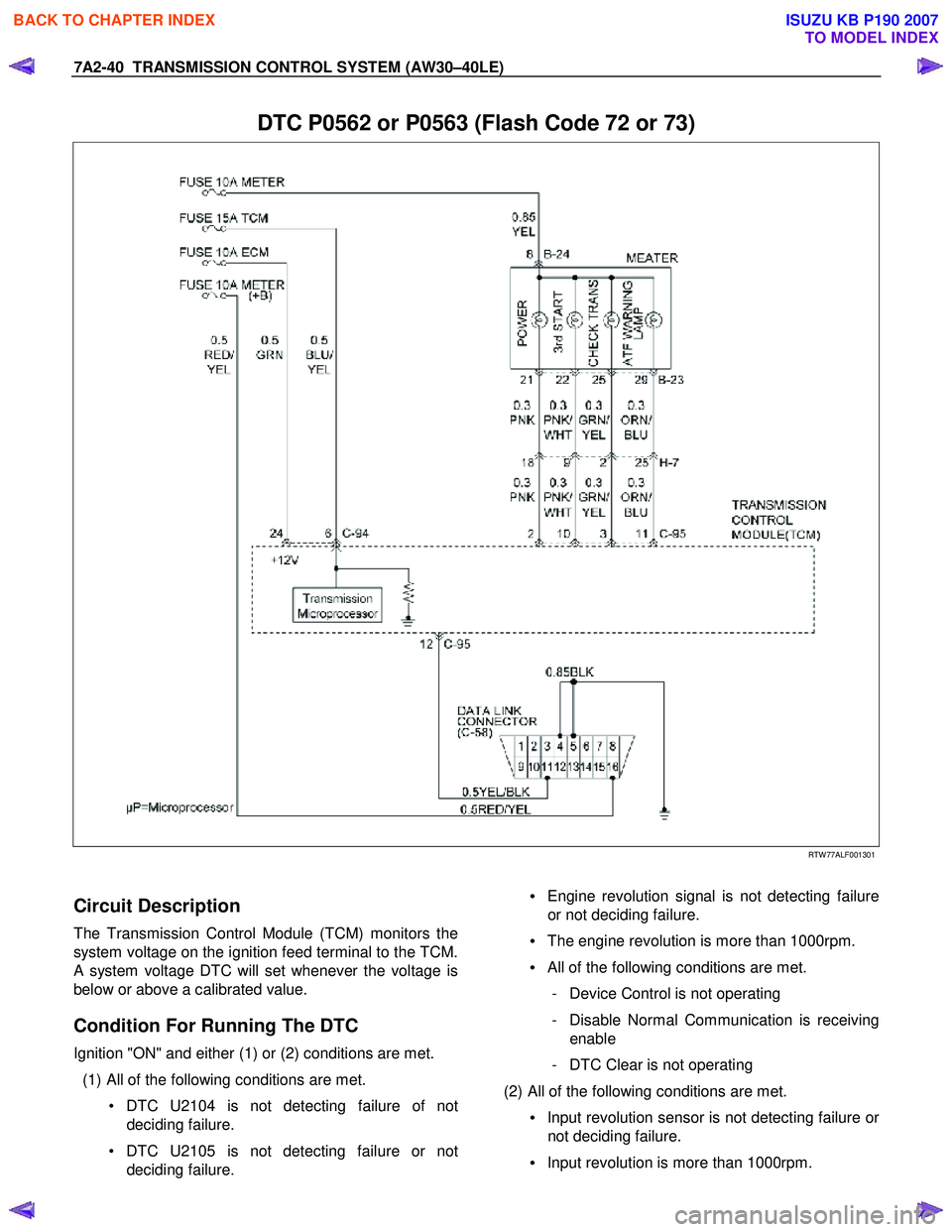
DTC P0562 or P0563 (Flash Code 72 or 73)
RTW 77ALF001301
Circuit Description
The Transmission Control Module (TCM) monitors the
system voltage on the ignition feed terminal to the TCM.
A system voltage DTC will set whenever the voltage is
below or above a calibrated value.
Condition For Running The DTC
Ignition "ON" and either (1) or (2) conditions are met.
(1) All of the following conditions are met. • DTC U2104 is not detecting failure of notdeciding failure.
• DTC U2105 is not detecting failure or not deciding failure.
• Engine revolution signal is not detecting failure
or not deciding failure.
• The engine revolution is more than 1000rpm.
• All of the following conditions are met.
- Device Control is not operating
- Disable Normal Communication is receiving enable
- DTC Clear is not operating
(2) All of the following conditions are met. • Input revolution sensor is not detecting failure o
r
not deciding failure.
• Input revolution is more than 1000rpm.
BACK TO CHAPTER INDEX
TO MODEL INDEX
ISUZU KB P190 2007
Page 4009 of 6020
TRANSMISSION CONTROL SYSTEM (AW30–40LE) 7A2-43
DTC P0602 (Flash Code 63)
Circuit Description
The Service Programming System (SPS) updates the
flash calibration files that are stored in a Transmission
Control Module (TCM). The calibration file
custom-tailors a module to a certain vehicle. The
calibration file contains data for things such as spark
curves and fuel control. W hen troubleshooting a
driveability problem, diagnosis may call fo
r
reprogramming the controller with newer calibration
information to correct a customer concern and Vehicle
Identification Number (VIN).
Condition for setting the DTC
W hen a VIN No. is not written into the TCM.
Action Taken When The DTC Sets
• DTC stored.
Conditions For Clearing The DTC
• The DTC can be cleared from the TCM history by
using a scan tool.
• The DTC will be cleared from history when the vehicle has achieved 40 warm-up cycles without a
failure reported.
•
After more than 1 second has elapsed after the
ignition key has been turned “ON”, short between
No.11 and No.4 (ground) of DLC (Data Link
Connector). Then, after 1 second, but within 6
seconds, discontinue shorting.
Diagnostic Aids
DTC P0602 is indicated when a VIN No. is not written
into the TCM.
A security lock is performed by SPS. And
not replace the TCM when DTC P0602 can repair b
y
SPS.
BACK TO CHAPTER INDEX
TO MODEL INDEX
ISUZU KB P190 2007
Page 4011 of 6020
TRANSMISSION CONTROL SYSTEM (AW30–40LE) 7A2-45
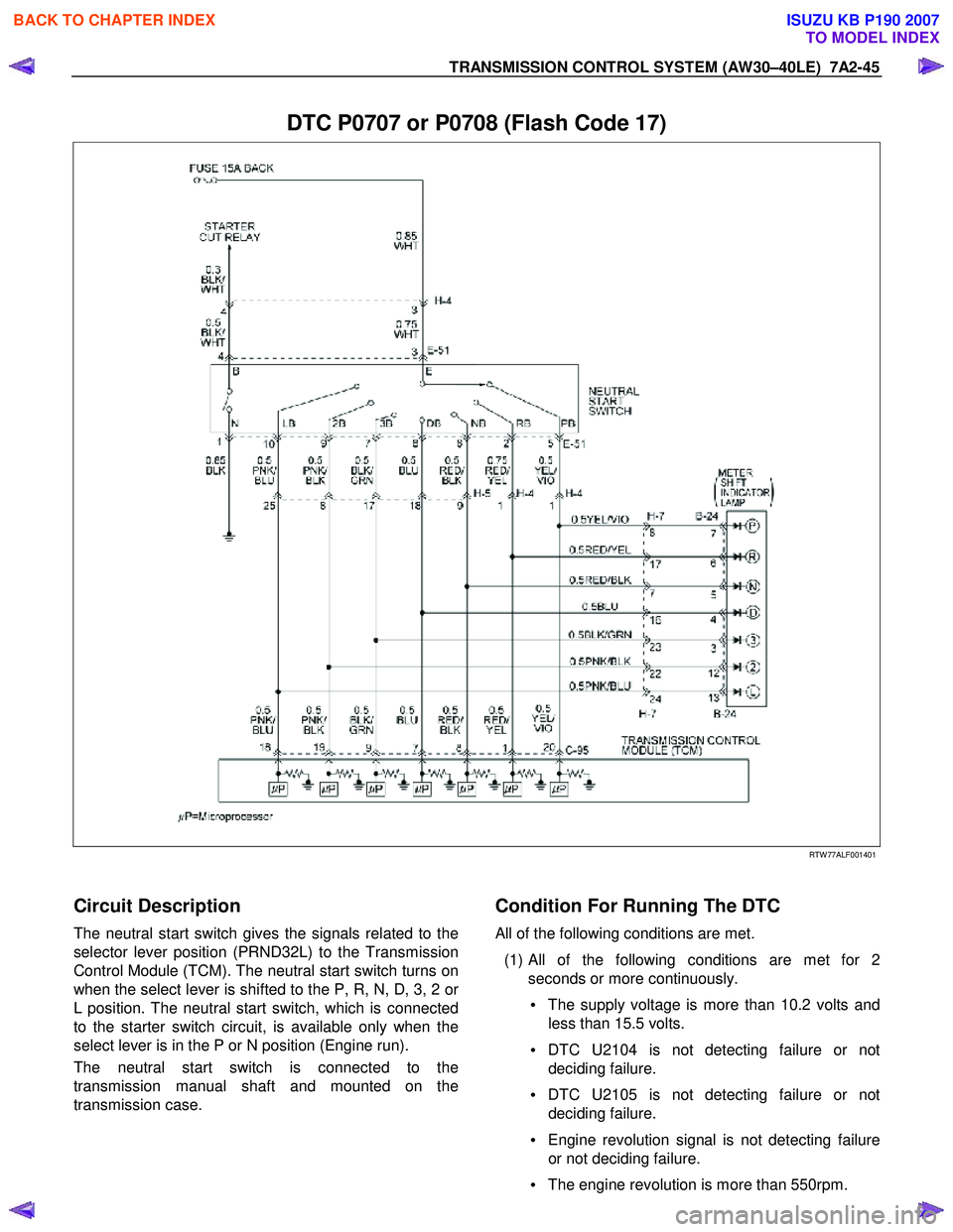
DTC P0707 or P0708 (Flash Code 17)
RTW 77ALF001401
Circuit Description
The neutral start switch gives the signals related to the
selector lever position (PRND32L) to the Transmission
Control Module (TCM). The neutral start switch turns on
when the select lever is shifted to the P, R, N, D, 3, 2 o
r
L position. The neutral start switch, which is connected
to the starter switch circuit, is available only when the
select lever is in the P or N position (Engine run).
The neutral start switch is connected to the
transmission manual shaft and mounted on the
transmission case.
Condition For Running The DTC
All of the following conditions are met.
(1) All of the following conditions are met for 2 seconds or more continuously.
• The supply voltage is more than 10.2 volts and
less than 15.5 volts.
• DTC U2104 is not detecting failure or not
deciding failure.
• DTC U2105 is not detecting failure or not
deciding failure.
• Engine revolution signal is not detecting failure
or not deciding failure.
• The engine revolution is more than 550rpm.
BACK TO CHAPTER INDEX
TO MODEL INDEX
ISUZU KB P190 2007
Page 4015 of 6020
TRANSMISSION CONTROL SYSTEM (AW30–40LE) 7A2-49
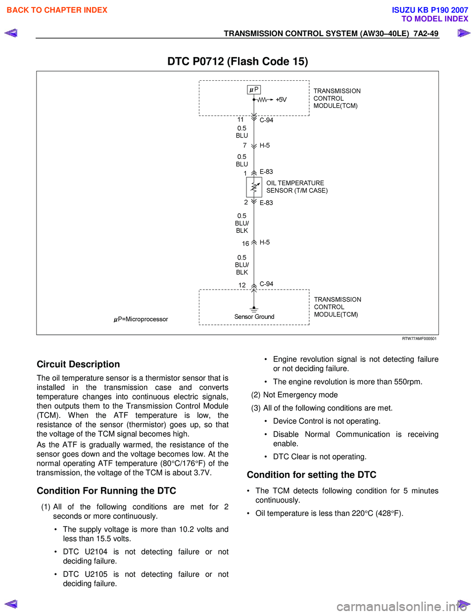
DTC P0712 (Flash Code 15)
RTW 77AMF000501
Circuit Description
The oil temperature sensor is a thermistor sensor that is
installed in the transmission case and converts
temperature changes into continuous electric signals,
then outputs them to the Transmission Control Module
(TCM). W hen the ATF temperature is low, the
resistance of the sensor (thermistor) goes up, so that
the voltage of the TCM signal becomes high.
As the ATF is gradually warmed, the resistance of the
sensor goes down and the voltage becomes low. At the
normal operating ATF temperature (80 °C/176 °F) of the
transmission, the voltage of the TCM is about 3.7V.
Condition For Running the DTC
(1) All of the following conditions are met for 2
seconds or more continuously.
• The supply voltage is more than 10.2 volts and less than 15.5 volts.
• DTC U2104 is not detecting failure or not deciding failure.
• DTC U2105 is not detecting failure or not deciding failure.
• Engine revolution signal is not detecting failure
or not deciding failure.
• The engine revolution is more than 550rpm.
(2) Not Emergency mode
(3) All of the following conditions are met. • Device Control is not operating.
• Disable Normal Communication is receiving enable.
• DTC Clear is not operating.
Condition for setting the DTC
• The TCM detects following condition for 5 minutes continuously.
• Oil temperature is less than 220 °C (428 °F).
BACK TO CHAPTER INDEX
TO MODEL INDEX
ISUZU KB P190 2007
Page 4018 of 6020

7A2-52 TRANSMISSION CONTROL SYSTEM (AW30–40LE)
DTC P0713 (Flash Code 16)
RTW 77AMF000501
Circuit Description
The oil temperature sensor is a thermistor sensor that is
installed in the transmission case and converts
temperature changes into continuous electric signals,
then outputs them to the Transmission Control Module
(TCM). W hen the ATF temperature is low, the
resistance of the sensor (thermistor) goes up, so that
the voltage of the TCM signal becomes high.
As the ATF is gradually warmed, the resistance of the
sensor goes down and the voltage becomes low. At the
normal operating ATF temperature (80 °C/176 °F) of the
transmission, the voltage of the TCM is about 3.7V.
Condition For Running The DTC
All of the following conditions are met.
(1) Detect the state which the all of the following conditions are met since ignition “ON” fo
r
accumulated 15 minutes or more.
• Except P or N position.
• Selector position switch is not detecting failure or not deciding failure.
• Output revolution is more than 600rpm.
• Output revolution sensor is not detecting failure
or not deciding failure.
(2) Engine coolant temperature ≧ 50 °C (122 °F)
(3) Engine coolant temperature signal is not detecting failure or not deciding failure.
Condition For Setting The DTC
The TCM detects following condition for 12 times
continuously.
• Oil temperature is more than –10 °C (14 °F).
Action Taken When The DTC Sets
• Control at A/T oil temperature 80 °C (176 °F).
• No squat control.
• No slope control.
• No 3rd start mode.
• No line pressure reduction at gear change.
• No coast control.
• No line pressure reduction control at garage.
• No shift solenoid functional failure detection.
BACK TO CHAPTER INDEX
TO MODEL INDEX
ISUZU KB P190 2007
Page 4021 of 6020
TRANSMISSION CONTROL SYSTEM (AW30–40LE) 7A2-55
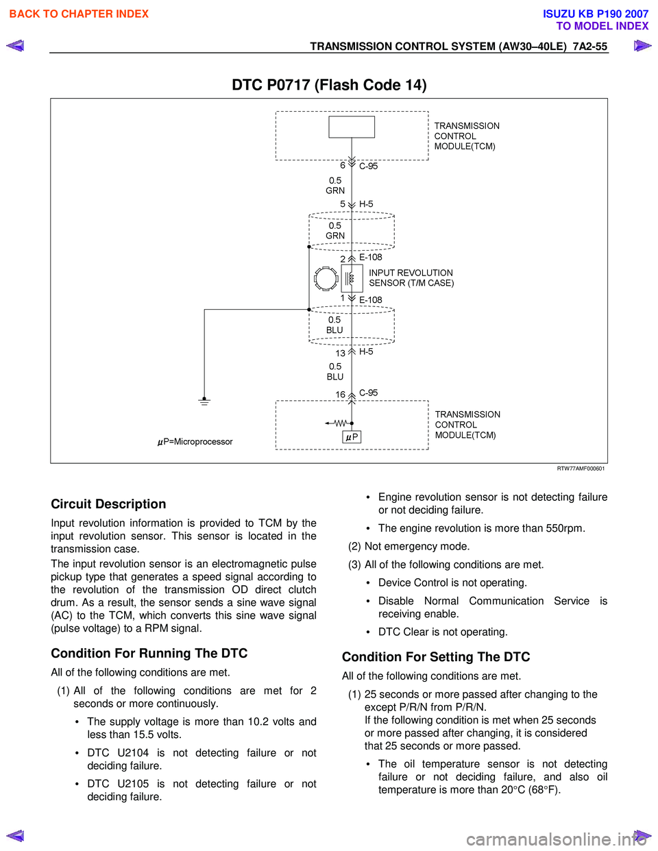
DTC P0717 (Flash Code 14)
RTW 77AMF000601
Circuit Description
Input revolution information is provided to TCM by the
input revolution sensor. This sensor is located in the
transmission case.
The input revolution sensor is an electromagnetic pulse
pickup type that generates a speed signal according to
the revolution of the transmission OD direct clutch
drum. As a result, the sensor sends a sine wave signal
(AC) to the TCM, which converts this sine wave signal
(pulse voltage) to a RPM signal.
Condition For Running The DTC
All of the following conditions are met.
(1)
All of the following conditions are met for 2
seconds or more continuously.
• The supply voltage is more than 10.2 volts and
less than 15.5 volts.
• DTC U2104 is not detecting failure or not
deciding failure.
• DTC U2105 is not detecting failure or not
deciding failure.
• Engine revolution sensor is not detecting failure
or not deciding failure.
• The engine revolution is more than 550rpm.
(2) Not emergency mode.
(3) All of the following conditions are met. • Device Control is not operating.
• Disable Normal Communication Service is
receiving enable.
• DTC Clear is not operating.
Condition For Setting The DTC
All of the following conditions are met.
(1) 25 seconds or more passed after changing to the except P/R/N from P/R/N.
If the following condition is met when 25 seconds
or more passed after changing, it is considered
that 25 seconds or more passed.
• The oil temperature sensor is not detecting
failure or not deciding failure, and also oil
temperature is more than 20 °C (68 °F).
BACK TO CHAPTER INDEX
TO MODEL INDEX
ISUZU KB P190 2007