2007 ISUZU KB P190 FLASH CODE
[x] Cancel search: FLASH CODEPage 1856 of 6020
ENGINE CONTROL SYSTEM (4JK1/4JJ1) 6E-239
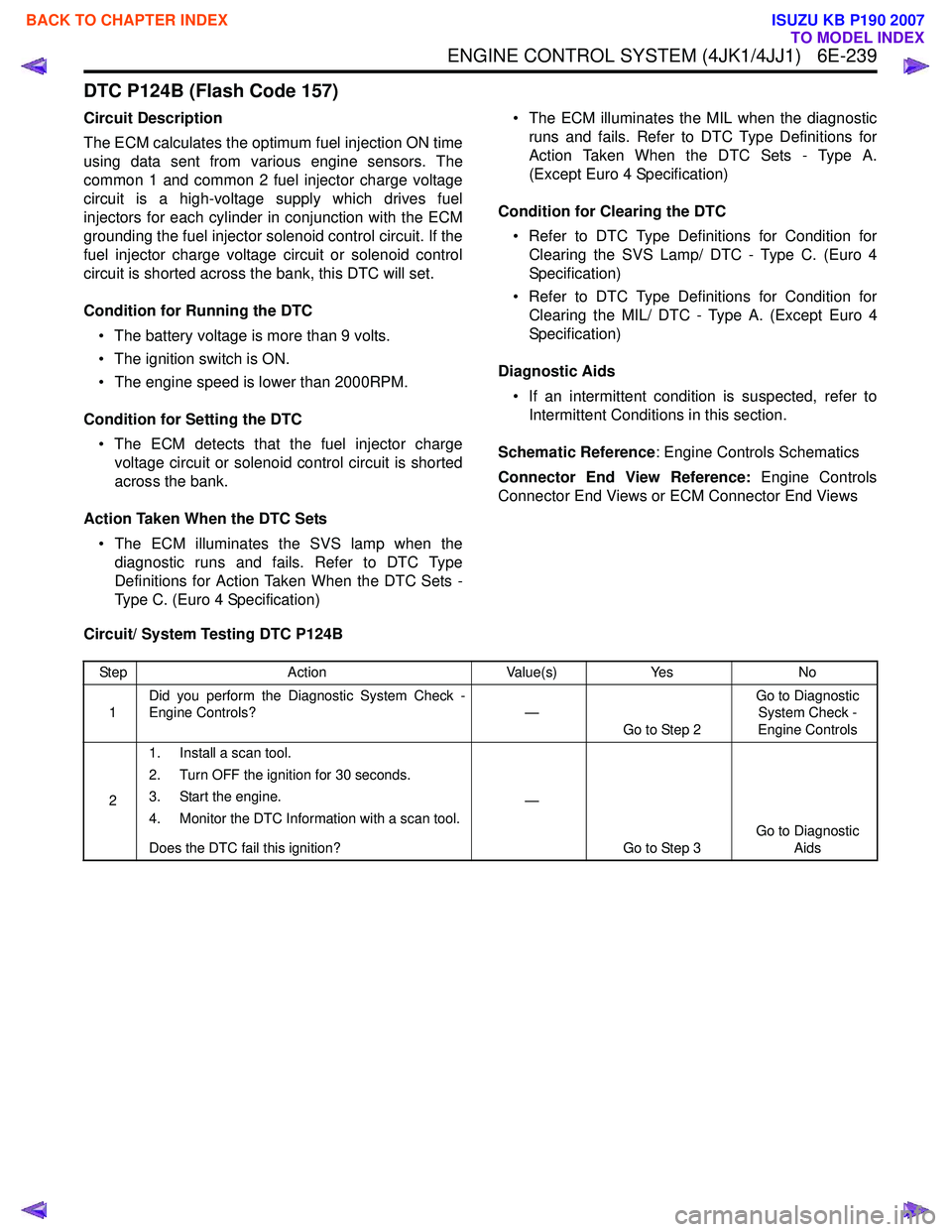
DTC P124B (Flash Code 157)
Circuit Description
The ECM calculates the optimum fuel injection ON time
using data sent from various engine sensors. The
common 1 and common 2 fuel injector charge voltage
circuit is a high-voltage supply which drives fuel
injectors for each cylinder in conjunction with the ECM
grounding the fuel injector solenoid control circuit. If the
fuel injector charge voltage circuit or solenoid control
circuit is shorted across the bank, this DTC will set.
Condition for Running the DTC • The battery voltage is more than 9 volts.
• The ignition switch is ON.
• The engine speed is lower than 2000RPM.
Condition for Setting the DTC • The ECM detects that the fuel injector charge voltage circuit or solenoid control circuit is shorted
across the bank.
Action Taken When the DTC Sets • The ECM illuminates the SVS lamp when the diagnostic runs and fails. Refer to DTC Type
Definitions for Action Taken When the DTC Sets -
Type C. (Euro 4 Specification) • The ECM illuminates the MIL when the diagnostic
runs and fails. Refer to DTC Type Definitions for
Action Taken When the DTC Sets - Type A.
(Except Euro 4 Specification)
Condition for Clearing the DTC • Refer to DTC Type Definitions for Condition for Clearing the SVS Lamp/ DTC - Type C. (Euro 4
Specification)
• Refer to DTC Type Definitions for Condition for Clearing the MIL/ DTC - Type A. (Except Euro 4
Specification)
Diagnostic Aids • If an intermittent condition is suspected, refer to Intermittent Conditions in this section.
Schematic Reference : Engine Controls Schematics
Connector End View Reference: Engine Controls
Connector End Views or ECM Connector End Views
Circuit/ System Testing DTC P124B
Step Action Value(s)Yes No
1 Did you perform the Diagnostic System Check -
Engine Controls? —
Go to Step 2 Go to Diagnostic
System Check -
Engine Controls
2 1. Install a scan tool.
2. Turn OFF the ignition for 30 seconds.
3. Start the engine.
4. Monitor the DTC Information with a scan tool.
Does the DTC fail this ignition? —
Go to Step 3 Go to Diagnostic
Aids
BACK TO CHAPTER INDEX
TO MODEL INDEX
ISUZU KB P190 2007
Page 1859 of 6020
6E-242 ENGINE CONTROL SYSTEM (4JK1/4JJ1)
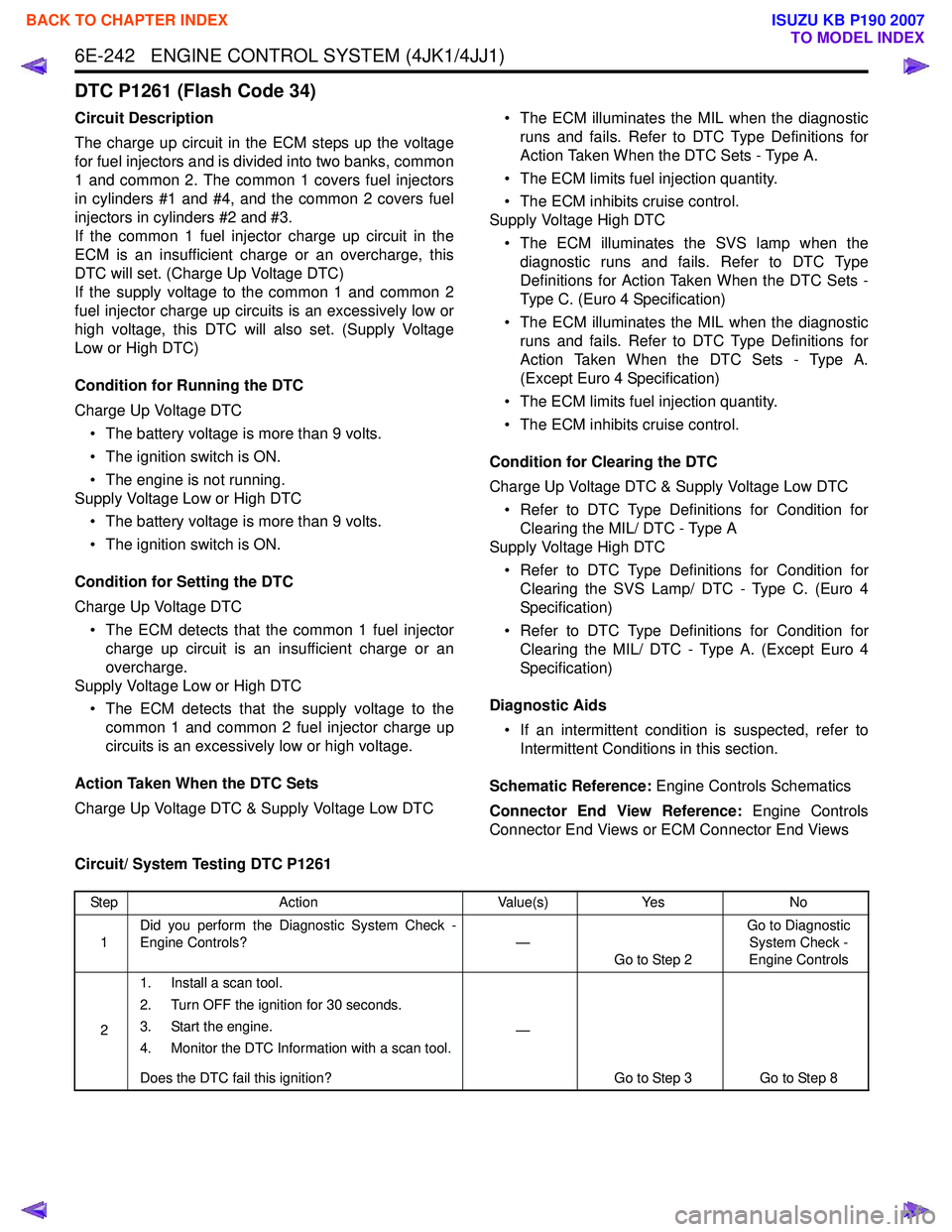
DTC P1261 (Flash Code 34)
Circuit Description
The charge up circuit in the ECM steps up the voltage
for fuel injectors and is divided into two banks, common
1 and common 2. The common 1 covers fuel injectors
in cylinders #1 and #4, and the common 2 covers fuel
injectors in cylinders #2 and #3.
If the common 1 fuel injector charge up circuit in the
ECM is an insufficient charge or an overcharge, this
DTC will set. (Charge Up Voltage DTC)
If the supply voltage to the common 1 and common 2
fuel injector charge up circuits is an excessively low or
high voltage, this DTC will also set. (Supply Voltage
Low or High DTC)
Condition for Running the DTC
Charge Up Voltage DTC • The battery voltage is more than 9 volts.
• The ignition switch is ON.
• The engine is not running.
Supply Voltage Low or High DTC
• The battery voltage is more than 9 volts.
• The ignition switch is ON.
Condition for Setting the DTC
Charge Up Voltage DTC • The ECM detects that the common 1 fuel injector charge up circuit is an insufficient charge or an
overcharge.
Supply Voltage Low or High DTC
• The ECM detects that the supply voltage to the common 1 and common 2 fuel injector charge up
circuits is an excessively low or high voltage.
Action Taken When the DTC Sets
Charge Up Voltage DTC & Supply Voltage Low DTC • The ECM illuminates the MIL when the diagnostic
runs and fails. Refer to DTC Type Definitions for
Action Taken When the DTC Sets - Type A.
• The ECM limits fuel injection quantity.
• The ECM inhibits cruise control.
Supply Voltage High DTC
• The ECM illuminates the SVS lamp when the diagnostic runs and fails. Refer to DTC Type
Definitions for Action Taken When the DTC Sets -
Type C. (Euro 4 Specification)
• The ECM illuminates the MIL when the diagnostic runs and fails. Refer to DTC Type Definitions for
Action Taken When the DTC Sets - Type A.
(Except Euro 4 Specification)
• The ECM limits fuel injection quantity.
• The ECM inhibits cruise control.
Condition for Clearing the DTC
Charge Up Voltage DTC & Supply Voltage Low DTC • Refer to DTC Type Definitions for Condition for Clearing the MIL/ DTC - Type A
Supply Voltage High DTC
• Refer to DTC Type Definitions for Condition for Clearing the SVS Lamp/ DTC - Type C. (Euro 4
Specification)
• Refer to DTC Type Definitions for Condition for Clearing the MIL/ DTC - Type A. (Except Euro 4
Specification)
Diagnostic Aids • If an intermittent condition is suspected, refer to Intermittent Conditions in this section.
Schematic Reference: Engine Controls Schematics
Connector End View Reference: Engine Controls
Connector End Views or ECM Connector End Views
Circuit/ System Testing DTC P1261
Step Action Value(s)Yes No
1 Did you perform the Diagnostic System Check -
Engine Controls? —
Go to Step 2 Go to Diagnostic
System Check -
Engine Controls
2 1. Install a scan tool.
2. Turn OFF the ignition for 30 seconds.
3. Start the engine.
4. Monitor the DTC Information with a scan tool.
Does the DTC fail this ignition? —
Go to Step 3 Go to Step 8
BACK TO CHAPTER INDEX
TO MODEL INDEX
ISUZU KB P190 2007
Page 1861 of 6020
6E-244 ENGINE CONTROL SYSTEM (4JK1/4JJ1)
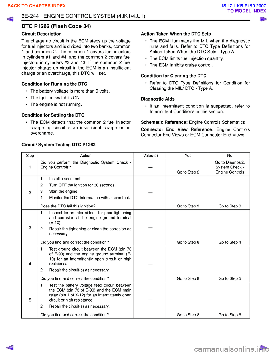
DTC P1262 (Flash Code 34)
Circuit Description
The charge up circuit in the ECM steps up the voltage
for fuel injectors and is divided into two banks, common
1 and common 2. The common 1 covers fuel injectors
in cylinders #1 and #4, and the common 2 covers fuel
injectors in cylinders #2 and #3. If the common 2 fuel
injector charge up circuit in the ECM is an insufficient
charge or an overcharge, this DTC will set.
Condition for Running the DTC • The battery voltage is more than 9 volts.
• The ignition switch is ON.
• The engine is not running.
Condition for Setting the DTC • The ECM detects that the common 2 fuel injector charge up circuit is an insufficient charge or an
overcharge. Action Taken When the DTC Sets
• The ECM illuminates the MIL when the diagnostic runs and fails. Refer to DTC Type Definitions for
Action Taken When the DTC Sets - Type A.
• The ECM limits fuel injection quantity.
• The ECM inhibits cruise control.
Condition for Clearing the DTC • Refer to DTC Type Definitions for Condition for Clearing the MIL/ DTC - Type A.
Diagnostic Aids • If an intermittent condition is suspected, refer to Intermittent Conditions in this section.
Schematic Reference: Engine Controls Schematics
Connector End View Reference: Engine Controls
Connector End Views or ECM Connector End Views
Circuit/ System Testing DTC P1262
Step Action Value(s)Yes No
1 Did you perform the Diagnostic System Check -
Engine Controls? —
Go to Step 2 Go to Diagnostic
System Check -
Engine Controls
2 1. Install a scan tool.
2. Turn OFF the ignition for 30 seconds.
3. Start the engine.
4. Monitor the DTC Information with a scan tool.
Does the DTC fail this ignition? —
Go to Step 3 Go to Step 8
3 1. Inspect for an intermittent, for poor tightening
and corrosion at the engine ground terminal
(E-10).
2. Repair the tightening or clean the corrosion as necessary.
Did you find and correct the condition? —
Go to Step 8 Go to Step 4
4 1. Test ground circuit between the ECM (pin 73
of E-90) and the engine ground terminal (E-
10) for an intermittently open circuit or high
resistance.
2. Repair the circuit(s) as necessary.
Did you find and correct the condition? —
Go to Step 8 Go to Step 5
5 1. Test the battery voltage feed circuit between
the ECM (pin 73 of E-90) and the ECM main
relay (pin 1 of X-12) for an intermittently open
circuit or high resistance.
2. Repair the circuit(s) as necessary.
Did you find and correct the condition? —
Go to Step 8 Go to Step 6
BACK TO CHAPTER INDEX
TO MODEL INDEX
ISUZU KB P190 2007
Page 1863 of 6020
6E-246 ENGINE CONTROL SYSTEM (4JK1/4JJ1)
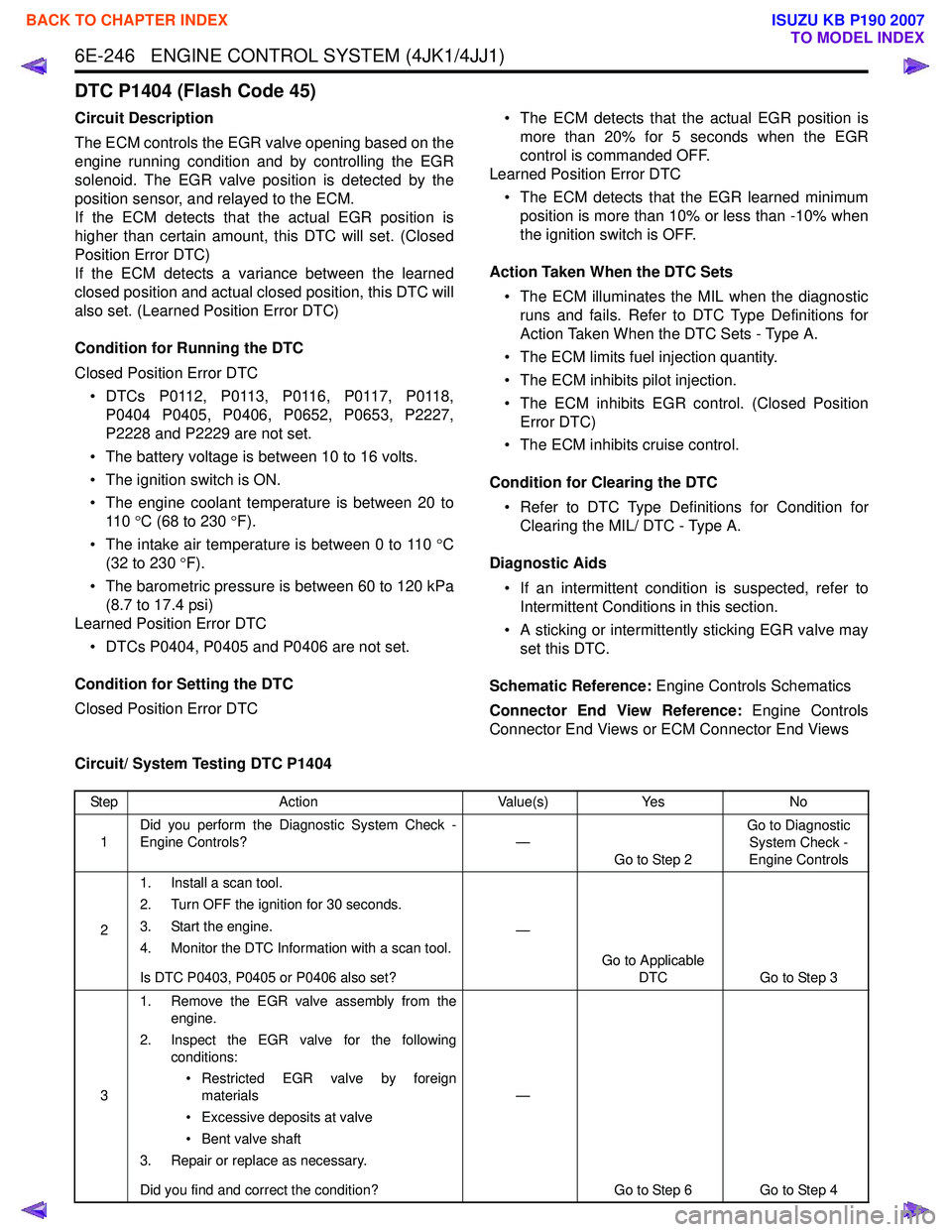
DTC P1404 (Flash Code 45)
Circuit Description
The ECM controls the EGR valve opening based on the
engine running condition and by controlling the EGR
solenoid. The EGR valve position is detected by the
position sensor, and relayed to the ECM.
If the ECM detects that the actual EGR position is
higher than certain amount, this DTC will set. (Closed
Position Error DTC)
If the ECM detects a variance between the learned
closed position and actual closed position, this DTC will
also set. (Learned Position Error DTC)
Condition for Running the DTC
Closed Position Error DTC • DTCs P0112, P0113, P0116, P0117, P0118, P0404 P0405, P0406, P0652, P0653, P2227,
P2228 and P2229 are not set.
• The battery voltage is between 10 to 16 volts.
• The ignition switch is ON.
• The engine coolant temperature is between 20 to 11 0 °C (68 to 230 °F).
• The intake air temperature is between 0 to 110 °C
(32 to 230 °F).
• The barometric pressure is between 60 to 120 kPa (8.7 to 17.4 psi)
Learned Position Error DTC
• DTCs P0404, P0405 and P0406 are not set.
Condition for Setting the DTC
Closed Position Error DTC • The ECM detects that the actual EGR position is
more than 20% for 5 seconds when the EGR
control is commanded OFF.
Learned Position Error DTC
• The ECM detects that the EGR learned minimum position is more than 10% or less than -10% when
the ignition switch is OFF.
Action Taken When the DTC Sets • The ECM illuminates the MIL when the diagnostic runs and fails. Refer to DTC Type Definitions for
Action Taken When the DTC Sets - Type A.
• The ECM limits fuel injection quantity.
• The ECM inhibits pilot injection.
• The ECM inhibits EGR control. (Closed Position Error DTC)
• The ECM inhibits cruise control.
Condition for Clearing the DTC • Refer to DTC Type Definitions for Condition for Clearing the MIL/ DTC - Type A.
Diagnostic Aids • If an intermittent condition is suspected, refer to Intermittent Conditions in this section.
• A sticking or intermittently sticking EGR valve may set this DTC.
Schematic Reference: Engine Controls Schematics
Connector End View Reference: Engine Controls
Connector End Views or ECM Connector End Views
Circuit/ System Testing DTC P1404
Step Action Value(s)Yes No
1 Did you perform the Diagnostic System Check -
Engine Controls? —
Go to Step 2 Go to Diagnostic
System Check -
Engine Controls
2 1. Install a scan tool.
2. Turn OFF the ignition for 30 seconds.
3. Start the engine.
4. Monitor the DTC Information with a scan tool.
Is DTC P0403, P0405 or P0406 also set? —
Go to Applicable DTC Go to Step 3
3 1. Remove the EGR valve assembly from the
engine.
2. Inspect the EGR valve for the following conditions:
• Restricted EGR valve by foreign materials
• Excessive deposits at valve
• Bent valve shaft
3. Repair or replace as necessary.
Did you find and correct the condition? —
Go to Step 6 Go to Step 4
BACK TO CHAPTER INDEX
TO MODEL INDEX
ISUZU KB P190 2007
Page 1865 of 6020
6E-248 ENGINE CONTROL SYSTEM (4JK1/4JJ1)
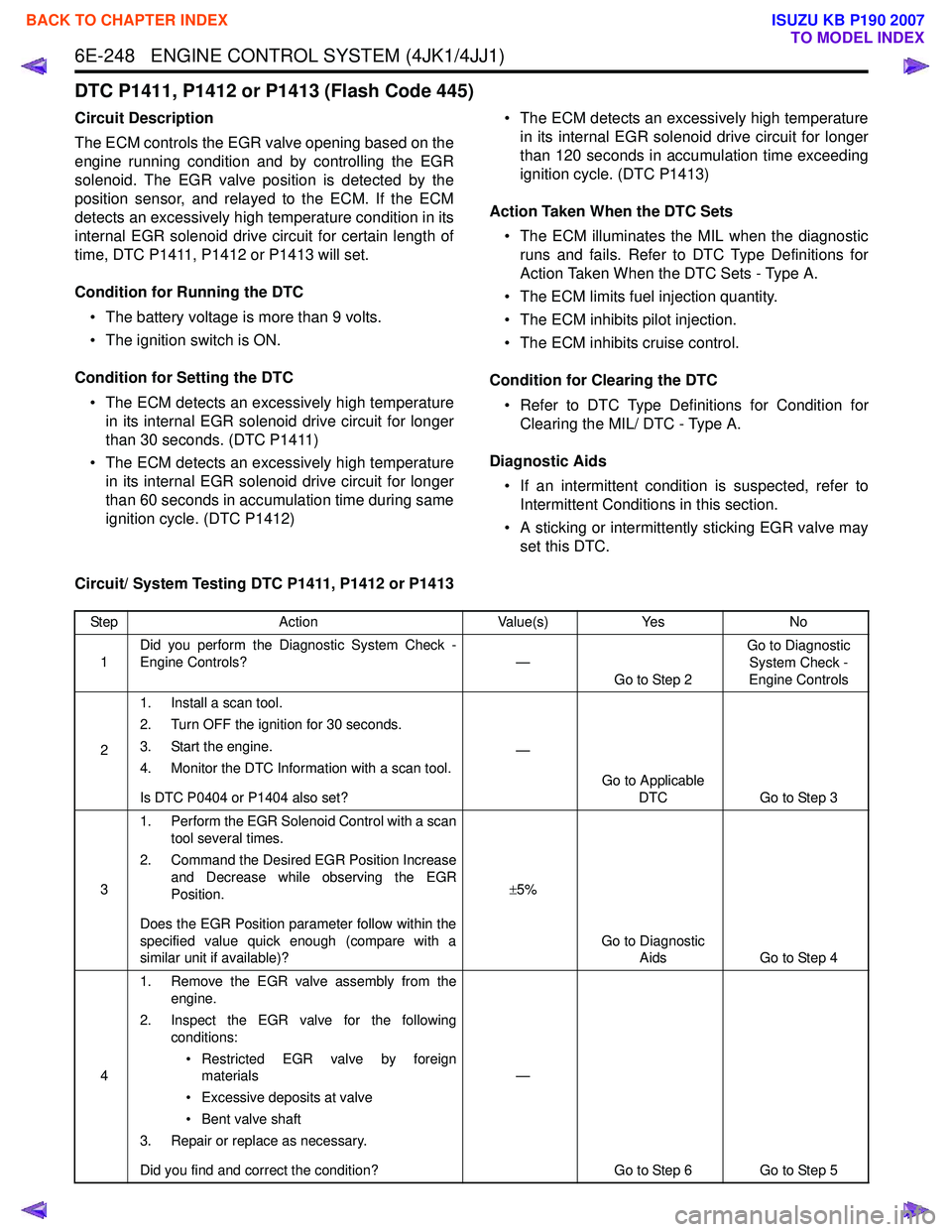
DTC P1411, P1412 or P1413 (Flash Code 445)
Circuit Description
The ECM controls the EGR valve opening based on the
engine running condition and by controlling the EGR
solenoid. The EGR valve position is detected by the
position sensor, and relayed to the ECM. If the ECM
detects an excessively high temperature condition in its
internal EGR solenoid drive circuit for certain length of
time, DTC P1411, P1412 or P1413 will set.
Condition for Running the DTC • The battery voltage is more than 9 volts.
• The ignition switch is ON.
Condition for Setting the DTC • The ECM detects an excessively high temperature in its internal EGR solenoid drive circuit for longer
than 30 seconds. (DTC P1411)
• The ECM detects an excessively high temperature in its internal EGR solenoid drive circuit for longer
than 60 seconds in accumulation time during same
ignition cycle. (DTC P1412) • The ECM detects an excessively high temperature
in its internal EGR solenoid drive circuit for longer
than 120 seconds in accumulation time exceeding
ignition cycle. (DTC P1413)
Action Taken When the DTC Sets • The ECM illuminates the MIL when the diagnostic runs and fails. Refer to DTC Type Definitions for
Action Taken When the DTC Sets - Type A.
• The ECM limits fuel injection quantity.
• The ECM inhibits pilot injection.
• The ECM inhibits cruise control.
Condition for Clearing the DTC • Refer to DTC Type Definitions for Condition for Clearing the MIL/ DTC - Type A.
Diagnostic Aids • If an intermittent condition is suspected, refer to Intermittent Conditions in this section.
• A sticking or intermittently sticking EGR valve may set this DTC.
Circuit/ System Testing DTC P1411, P1412 or P1413
Step Action Value(s)Yes No
1 Did you perform the Diagnostic System Check -
Engine Controls? —
Go to Step 2 Go to Diagnostic
System Check -
Engine Controls
2 1. Install a scan tool.
2. Turn OFF the ignition for 30 seconds.
3. Start the engine.
4. Monitor the DTC Information with a scan tool.
Is DTC P0404 or P1404 also set? —
Go to Applicable DTC Go to Step 3
3 1. Perform the EGR Solenoid Control with a scan
tool several times.
2. Command the Desired EGR Position Increase and Decrease while observing the EGR
Position.
Does the EGR Position parameter follow within the
specified value quick enough (compare with a
similar unit if available)? ±
5%
Go to Diagnostic Aids Go to Step 4
4 1. Remove the EGR valve assembly from the
engine.
2. Inspect the EGR valve for the following conditions:
• Restricted EGR valve by foreign materials
• Excessive deposits at valve
• Bent valve shaft
3. Repair or replace as necessary.
Did you find and correct the condition? —
Go to Step 6 Go to Step 5
BACK TO CHAPTER INDEX
TO MODEL INDEX
ISUZU KB P190 2007
Page 1867 of 6020
6E-250 ENGINE CONTROL SYSTEM (4JK1/4JJ1)
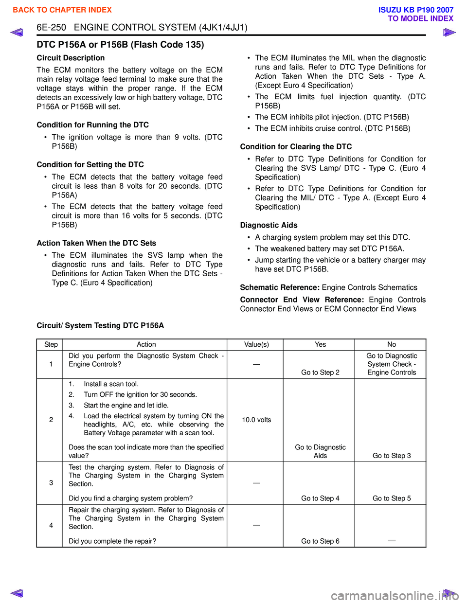
DTC P156A or P156B (Flash Code 135)
Circuit Description
The ECM monitors the battery voltage on the ECM
main relay voltage feed terminal to make sure that the
voltage stays within the proper range. If the ECM
detects an excessively low or high battery voltage, DTC
P156A or P156B will set.
Condition for Running the DTC • The ignition voltage is more than 9 volts. (DTC P156B)
Condition for Setting the DTC • The ECM detects that the battery voltage feed circuit is less than 8 volts for 20 seconds. (DTC
P156A)
• The ECM detects that the battery voltage feed circuit is more than 16 volts for 5 seconds. (DTC
P156B)
Action Taken When the DTC Sets • The ECM illuminates the SVS lamp when the diagnostic runs and fails. Refer to DTC Type
Definitions for Action Taken When the DTC Sets -
Type C. (Euro 4 Specification) • The ECM illuminates the MIL when the diagnostic
runs and fails. Refer to DTC Type Definitions for
Action Taken When the DTC Sets - Type A.
(Except Euro 4 Specification)
• The ECM limits fuel injection quantity. (DTC P156B)
• The ECM inhibits pilot injection. (DTC P156B)
• The ECM inhibits cruise control. (DTC P156B)
Condition for Clearing the DTC • Refer to DTC Type Definitions for Condition for Clearing the SVS Lamp/ DTC - Type C. (Euro 4
Specification)
• Refer to DTC Type Definitions for Condition for Clearing the MIL/ DTC - Type A. (Except Euro 4
Specification)
Diagnostic Aids • A charging system problem may set this DTC.
• The weakened battery may set DTC P156A.
• Jump starting the vehicle or a battery charger may have set DTC P156B.
Schematic Reference: Engine Controls Schematics
Connector End View Reference: Engine Controls
Connector End Views or ECM Connector End Views
Circuit/ System Testing DTC P156A
Step Action Value(s)Yes No
1 Did you perform the Diagnostic System Check -
Engine Controls? —
Go to Step 2 Go to Diagnostic
System Check -
Engine Controls
2 1. Install a scan tool.
2. Turn OFF the ignition for 30 seconds.
3. Start the engine and let idle.
4. Load the electrical system by turning ON the headlights, A/C, etc. while observing the
Battery Voltage parameter with a scan tool.
Does the scan tool indicate more than the specified
value? 10.0 volts
Go to Diagnostic Aids Go to Step 3
3 Test the charging system. Refer to Diagnosis of
The Charging System in the Charging System
Section.
Did you find a charging system problem? —
Go to Step 4 Go to Step 5
4 Repair the charging system. Refer to Diagnosis of
The Charging System in the Charging System
Section.
Did you complete the repair? —
Go to Step 6
—
BACK TO CHAPTER INDEX
TO MODEL INDEX
ISUZU KB P190 2007
Page 1870 of 6020
ENGINE CONTROL SYSTEM (4JK1/4JJ1) 6E-253
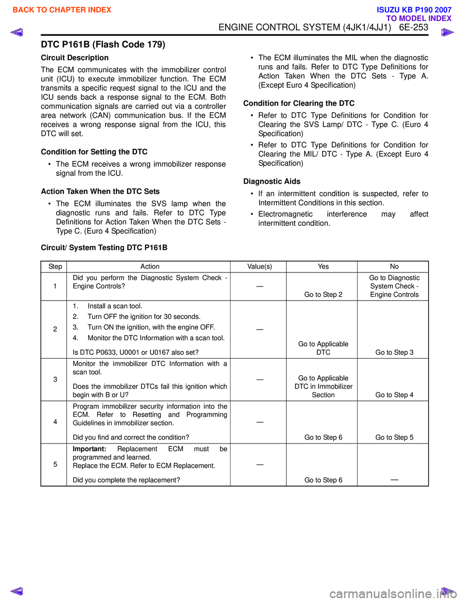
DTC P161B (Flash Code 179)
Circuit Description
The ECM communicates with the immobilizer control
unit (ICU) to execute immobilizer function. The ECM
transmits a specific request signal to the ICU and the
ICU sends back a response signal to the ECM. Both
communication signals are carried out via a controller
area network (CAN) communication bus. If the ECM
receives a wrong response signal from the ICU, this
DTC will set.
Condition for Setting the DTC • The ECM receives a wrong immobilizer response signal from the ICU.
Action Taken When the DTC Sets • The ECM illuminates the SVS lamp when the diagnostic runs and fails. Refer to DTC Type
Definitions for Action Taken When the DTC Sets -
Type C. (Euro 4 Specification) • The ECM illuminates the MIL when the diagnostic
runs and fails. Refer to DTC Type Definitions for
Action Taken When the DTC Sets - Type A.
(Except Euro 4 Specification)
Condition for Clearing the DTC • Refer to DTC Type Definitions for Condition for Clearing the SVS Lamp/ DTC - Type C. (Euro 4
Specification)
• Refer to DTC Type Definitions for Condition for Clearing the MIL/ DTC - Type A. (Except Euro 4
Specification)
Diagnostic Aids • If an intermittent condition is suspected, refer to Intermittent Conditions in this section.
• Electromagnetic interference may affect intermittent condition.
Circuit/ System Testing DTC P161B
Step Action Value(s)Yes No
1 Did you perform the Diagnostic System Check -
Engine Controls? —
Go to Step 2 Go to Diagnostic
System Check -
Engine Controls
2 1. Install a scan tool.
2. Turn OFF the ignition for 30 seconds.
3. Turn ON the ignition, with the engine OFF.
4. Monitor the DTC Information with a scan tool.
Is DTC P0633, U0001 or U0167 also set? —
Go to Applicable DTC Go to Step 3
3 Monitor the immobilizer DTC Information with a
scan tool.
Does the immobilizer DTCs fail this ignition which
begin with B or U? —
Go to Applicable
DTC in Immobilizer Section Go to Step 4
4 Program immobilizer security information into the
ECM. Refer to Resetting and Programming
Guidelines in immobilizer section.
Did you find and correct the condition? —
Go to Step 6 Go to Step 5
5 Important:
Replacement ECM must be
programmed and learned.
Replace the ECM. Refer to ECM Replacement.
Did you complete the replacement? —
Go to Step 6
—
BACK TO CHAPTER INDEX
TO MODEL INDEX
ISUZU KB P190 2007
Page 1872 of 6020
ENGINE CONTROL SYSTEM (4JK1/4JJ1) 6E-255
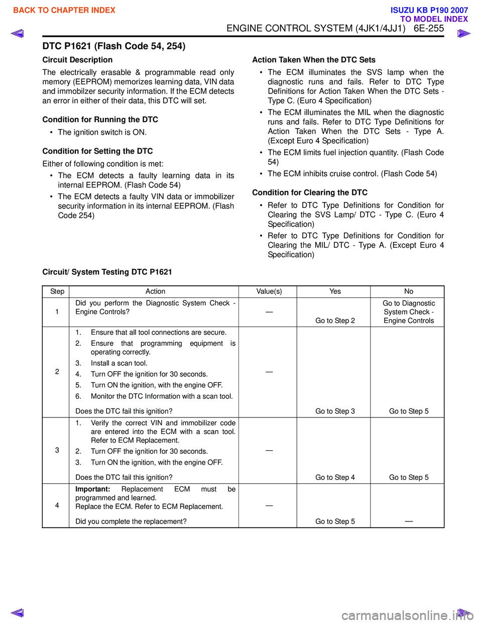
DTC P1621 (Flash Code 54, 254)
Circuit Description
The electrically erasable & programmable read only
memory (EEPROM) memorizes learning data, VIN data
and immobilzer security information. If the ECM detects
an error in either of their data, this DTC will set.
Condition for Running the DTC • The ignition switch is ON.
Condition for Setting the DTC
Either of following condition is met: • The ECM detects a faulty learning data in its internal EEPROM. (Flash Code 54)
• The ECM detects a faulty VIN data or immobilizer security information in its internal EEPROM. (Flash
Code 254) Action Taken When the DTC Sets
• The ECM illuminates the SVS lamp when the diagnostic runs and fails. Refer to DTC Type
Definitions for Action Taken When the DTC Sets -
Type C. (Euro 4 Specification)
• The ECM illuminates the MIL when the diagnostic runs and fails. Refer to DTC Type Definitions for
Action Taken When the DTC Sets - Type A.
(Except Euro 4 Specification)
• The ECM limits fuel injection quantity. (Flash Code 54)
• The ECM inhibits cruise control. (Flash Code 54)
Condition for Clearing the DTC • Refer to DTC Type Definitions for Condition for Clearing the SVS Lamp/ DTC - Type C. (Euro 4
Specification)
• Refer to DTC Type Definitions for Condition for Clearing the MIL/ DTC - Type A. (Except Euro 4
Specification)
Circuit/ System Testing DTC P1621
Step Action Value(s)Yes No
1 Did you perform the Diagnostic System Check -
Engine Controls? —
Go to Step 2 Go to Diagnostic
System Check -
Engine Controls
2 1. Ensure that all tool connections are secure.
2. Ensure that programming equipment is operating correctly.
3. Install a scan tool.
4. Turn OFF the ignition for 30 seconds.
5. Turn ON the ignition, with the engine OFF.
6. Monitor the DTC Information with a scan tool.
Does the DTC fail this ignition? —
Go to Step 3 Go to Step 5
3 1. Verify the correct VIN and immobilizer code
are entered into the ECM with a scan tool.
Refer to ECM Replacement.
2. Turn OFF the ignition for 30 seconds.
3. Turn ON the ignition, with the engine OFF.
Does the DTC fail this ignition? —
Go to Step 4 Go to Step 5
4 Important:
Replacement ECM must be
programmed and learned.
Replace the ECM. Refer to ECM Replacement.
Did you complete the replacement? —
Go to Step 5
—
BACK TO CHAPTER INDEX
TO MODEL INDEX
ISUZU KB P190 2007