2007 ISUZU KB P190 FLASH CODE
[x] Cancel search: FLASH CODEPage 2392 of 6020

6E–222 ENGINE DRIVEABILITY AND EMISSIONS
DIAGNOSTIC TROUBLE CODE (DTC) P1631 IMMOBILIZER WRONG SIGNAL
Condition for setting the DTC and action taken when the DTC sets
Circuit Description
The ECM decides whether that is an abnomality in the
immobilizer control system. DTC P1631 is recorded by
the ECM when received response was not correct.
Diagnostic Aids
Check for the following conditions:
• Poor connection at ECM and Immobilizer-Inspect harness connectors for backed out terminals,
improper mating, broken locks, improperly formed or damaged terminals, and poor terminal to wire
connection.
• Damaged harness-Inspect the wiring harness for damage, If the harness appears to be OK, disconnect
the ECM and Immobilizer, turn the ignition “ON” and
observe a voltmeter connected to the suspect driver
circuit at the ECM and Immobilizer harnass connector
while moving connectors and wiring harnesses
relates to the MIL. A change in voltage will indicate
the location of the fault.
Code Type DTC Name DTC Setting Condition Fail-Safe (Back Up)
P1631 - Immobilizer Wrong Signal Received response is not correct.1. Engine does not start.
2. Check engine lamp flash.
BACK TO CHAPTER INDEX
TO MODEL INDEX
ISUZU KB P190 2007
Page 2394 of 6020
6E–224 ENGINE DRIVEABILITY AND EMISSIONS
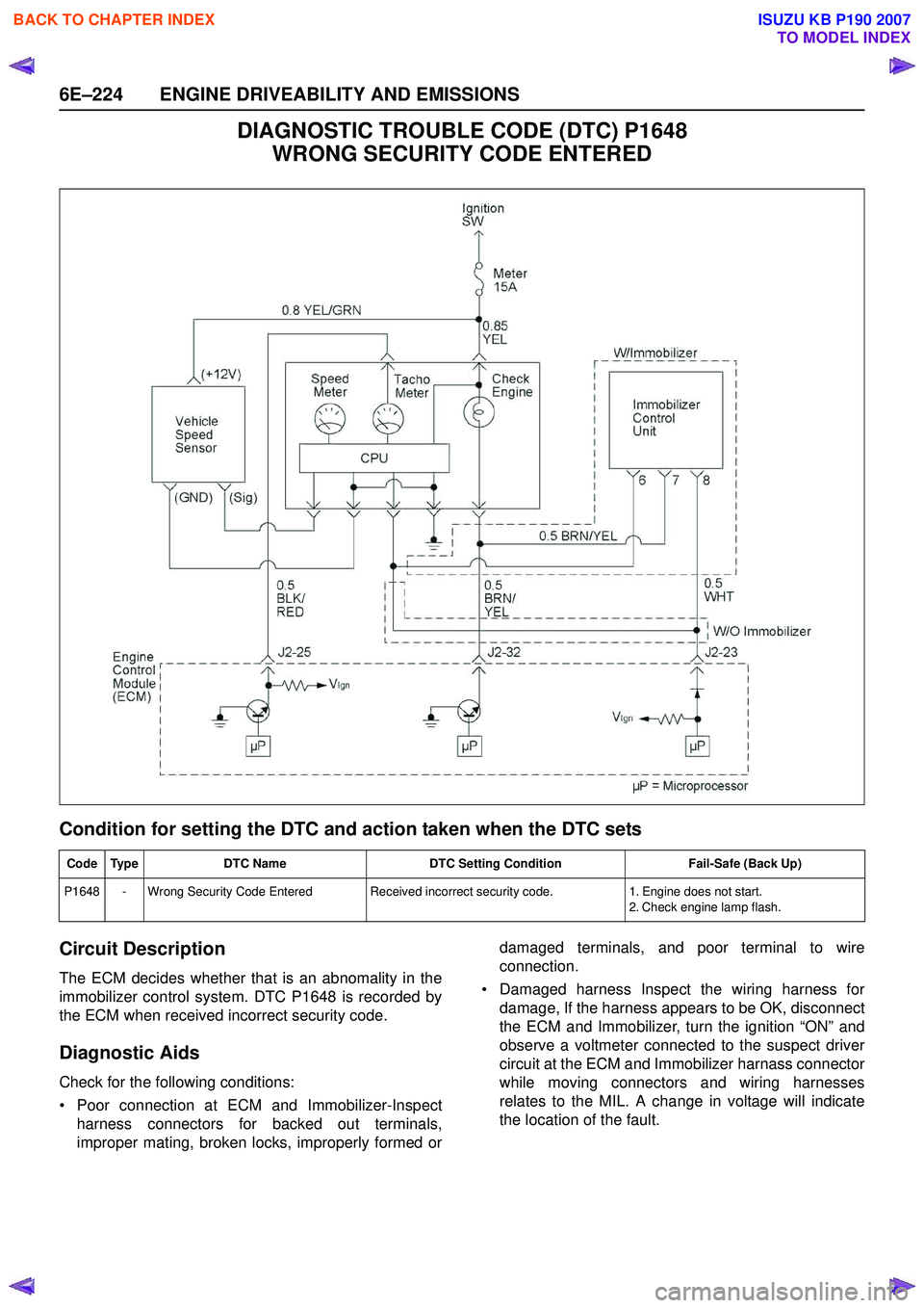
DIAGNOSTIC TROUBLE CODE (DTC) P1648 WRONG SECURITY CODE ENTERED
Condition for setting the DTC and action taken when the DTC sets
Circuit Description
The ECM decides whether that is an abnomality in the
immobilizer control system. DTC P1648 is recorded by
the ECM when received incorrect security code.
Diagnostic Aids
Check for the following conditions:
• Poor connection at ECM and Immobilizer-Inspect harness connectors for backed out terminals,
improper mating, broken locks, improperly formed or damaged terminals, and poor terminal to wire
connection.
• Damaged harness Inspect the wiring harness for damage, If the harness appears to be OK, disconnect
the ECM and Immobilizer, turn the ignition “ON” and
observe a voltmeter connected to the suspect driver
circuit at the ECM and Immobilizer harnass connector
while moving connectors and wiring harnesses
relates to the MIL. A change in voltage will indicate
the location of the fault.
Code Type DTC Name DTC Setting Condition Fail-Safe (Back Up)
P1648 - Wrong Security Code Entered Received incorrect security code. 1. Engine does not start.
2. Check engine lamp flash.
BACK TO CHAPTER INDEX
TO MODEL INDEX
ISUZU KB P190 2007
Page 2396 of 6020

6E–226 ENGINE DRIVEABILITY AND EMISSIONS
DIAGNOSTIC TROUBLE CODE (DTC) P1649
IMMOBILIZER FUNCTION NOT PROGRAMMED
Condition for setting the DTC and action taken when the DTC sets
Circuit Description
The ECM decides whether that is an abnomality in the
immobilizer control system. DTC P1649 is recorded by
the ECM when security code & secret key not
programmed.
Diagnostic Aids
Check for the following conditions:
• Poor connection at ECM and Immobilizer-Inspect harness connectors for backed out terminals, improper mating, broken locks, improperly formed or
damaged terminals, and poor terminal to wire
connection.
• Damaged harness Inspect the wiring harness for damage, If the harness appears to be OK, disconnect
the ECM and Immobilizer, turn the ignition “ON” and
observe a voltmeter connected to the suspect driver
circuit at the ECM and Immobilizer harnass connector
while moving connectors and wiring harnesses
relates to the MIL. A change in voltage will indicate
the location of the fault.
Code Type DTC Name DTC Setting Condition Fail-Safe (Back Up)
P1649 - Immobilizer Function Not Programmed Immobilizer function is not programmed in the ECM.1. Engine does not start.
2. Check engine lamp flash.
BACK TO CHAPTER INDEX
TO MODEL INDEX
ISUZU KB P190 2007
Page 3259 of 6020
Engine Management – V6 – General Information Page 6C1-1–17
3.9 Serial Data Communication System
The engine control module (ECM) communicates directly with the following control units using the General Motors local
area network (GM LAN) serial data communication protocol:
• Transmission control module (TCM) (if fitted)
• Powertrain interface module (PIM)
The immobiliser control unit (ICU) communicates directly with the PIM using Keyword 2000 serial data communication
protocol. Refer to 11A Immobiliser for further information
As the GM LAN serial data communication protocol is not compatible with the Keyword 2000 serial data communication
protocol, a powertrain interface module (PIM) is integrated to the serial data communication system to perform the
following tasks (Refer to 6E1 Powertrain Interface Module – V6):
• Translate the GM LAN serial data transmitted by the ECM into a Keyword 2000 serial data that can be received
and recognised by the ICU.
• Translate the cruise control switch, automatic transmission power mode switch and 3
rd start switch signal into a GM
LAN serial data that can be received and recognised by the ECM.
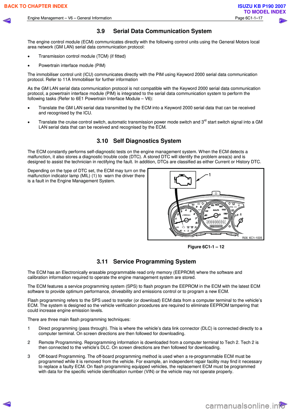
3.10 Self Diagnostics System
The ECM constantly performs self-diagnostic tests on the engine management system. W hen the ECM detects a
malfunction, it also stores a diagnostic trouble code (DTC). A stored DTC will identify the problem area(s) and is
designed to assist the technician in rectifying the fault. In addition, DTCs are classified as either Current or History DTC.
Depending on the type of DTC set, the ECM may turn on the
malfunction indicator lamp (MIL) (1) to warn the driver there
is a fault in the Engine Management System.
Figure 6C1-1 – 12
3.11 Service Programming System
The ECM has an Electronically erasable programmable read only memory (EEPROM) where the software and
calibration information required to operate the engine management system are stored.
The ECM features a service programming system (SPS) to flash program the EEPROM in the ECM with the latest ECM
software to provide optimum performance, driveability and emissions control or to program a new ECM.
Flash programming refers to the SPS used to transfer (or download) ECM data from a computer terminal to the vehicle’s
ECM. The system is designed so the vehicle verification procedures are required to eliminate EEPROM tampering that
could increase engine emission levels.
There are three main flash programming techniques:
1 Direct programming (pass through). This is where the vehicle’s data link connector (DLC) is connected directly to a computer terminal. On screen directions are then followed for downloading.
2 Remote Programming. Reprogramming information is downloaded from a computer terminal to Tech 2. Tech 2 is then connected to the vehicle’s DLC. On screen directions are then followed for downloading.
3 Off-board Programming. The off-board programming method is used when a re-programmable ECM must be programmed while it is removed from the vehicle. For example, an independent repair facility may find it necessary
to replace a faulty ECM. On flash programming equipped vehicles, the replacement ECM must be programmed
with data for the specific vehicle identification number (VIN) or the vehicle may not operate properly.
BACK TO CHAPTER INDEX
TO MODEL INDEX
ISUZU KB P190 2007
Page 3277 of 6020
Engine Management – V6 – General Information Page 6C1-1–35
5 Abbreviations and Glossary of
Te r m s
Abbreviations and terms used in this Section are listed below in alphabetical order with an explanation of the
abbreviation or term.
Abbreviation Description
A/C Air-conditioning
AC Alternating Current – An electrical current where the polarity is constantly changing between positive and
negative
A/F Air / Fuel (A/F Ratio)
Analogue Signal An electrical signal that constantly varies in voltage within a given parameter
Barometric Pressure Barometric absolute pressure (atmospheric pressure)
CAN Controller Area Network – A type of serial data for communication between electronic devices.
Catalytic Converter
A muffler-shaped device fitted in the exhaust system, usually close to the engine. Through chemical reaction,
a catalytic converter converts harmful gases produced by the combustion process such as HC, CO, and NOx,
into environmentally safe water vapour, carbon dioxide, and nitrogen.
CKT Circuit
Closed Loop A fuel control mode of operation that uses the signal from the exhaust oxygen sensor(s), to control the air / fuel
ratio precisely at a 14.7 to 1 ratio. This allows maximum efficiency of the catalytic converter.
CO Carbon Monoxide. One of the gases produced by the engine combustion process.
DC Direct Current
Digital Signal An electrical signal that is either on or off.
DLC
Data Link Connector. Used at the assembly plant to evaluate the engine management system. For service, it
allows the use of Tech 2 in performing system checks.
DLC Data Stream An output from the ECM initiated by Tech 2 and transmitted via the Data Link Connector(DLC).
DMM (10 M Ω) Digital Multimeter. A multipurpose meter that has capability of measuring voltage, current flow and resistance.
A digital multimeter has an input impedance of 10 M Ω (megohms), which means they draw very little power
from the device under test, they are very accurate and will not damage delicate electronic components
Driver An electronic device, usually a power transistor, that operates as an electrical switch.
DTC
Diagnostic Trouble Code. If a fault occurs in the engine management system, the ECM may set a four digit
diagnostic trouble code (DTC) which represents the fault condition. Tech 2 is used to interface with the ECM
and access the DTC(s). The ECM may also operate the malfunction indicator lamp in the instrument cluster.
Duty Cycle The time, in percentage, that a circuit is on versus off.
ECT Sensor
Engine Coolant Temperature sensor. A device that provides a variable voltage to the ECM based on the
temperature of the engine coolant.
EEPROM Electrically Erasable Programmable Read Only Memory. A type of read only memory (ROM) that can be
electrically programmed, erased and reprogrammed using Tech 2. Also referred to as Flash Memory
EMI or Electrical
Noise An unwanted signal interfering with a required signal. A common example is the effect of high voltage power
lines on an AM radio.
Engine Braking A condition where the engine is used to slow the vehicle on closed throttle or low gear.
EPROM Erasable Programmable Read Only Memory. A type of Read Only Memory (ROM) that can be erased with
ultraviolet light and then reprogrammed.
ESD Electrostatic Discharge. The discharge of static electricity which has built up on an insulated material
EVAP
Evaporative emission control system. Used to prevent fuel vapours from the fuel tank from entering into the
atmosphere. The vapours are stored in a canister that contains an activated charcoal element. The fuel
vapours are purged from the canister into the manifold to be burned in the engine.
GM LAN General Motors Local Area Network - A type of serial data for communication between electronic devices.
Fuse
A thin metal strip which melts when excessive current flows through it, creating an open circuit and protecting
a circuit from damage.
HC Hydrocarbon. Result of unburned fuel produced by incomplete combustion.
Heavy Throttle Approximately 3/4 of accelerator pedal travel (75% throttle position)
IAT Sensor
Intake Air Temperature sensor. A device that provides a variable voltage to the ECM based on the
temperature of air entering the intake system.
Ideal Mixture The air / fuel ratio which provides the best performance, while maintaining maximum conversion of exhaust
emissions, typically 14.7 to 1 on spark ignition engines
IGN Ignition
Inputs Information from sensors (MAF, TP, etc.) and switches (A/C request, etc.) used by the ECM to determine how
to control its outputs.
BACK TO CHAPTER INDEX
TO MODEL INDEX
ISUZU KB P190 2007
Page 3415 of 6020
Engine Management – V6 – Diagnostics Page 6C1-2–137
Conditions for Setting the DTC
DTC P0506
The actual engine speed is less than the desired idle speed by at least 100 rpm for 10 seconds.
DTC P0507
The actual engine speed is greater than the desired idle speed by at least 200 rpm for 10 seconds or the ECM detects
three fuel cut-offs due to an engine over speed condition while the engine is idling.
DTC P0638
The ECM detects the commanded duty cycle is greater than 80 percent for longer than 0.6 second.
DTC P1551
The ECM detects the TP sensor angle is outside the predetermined range of 1.8 – 13.0 percent when the TAC motor is
deactivated.
DTC 2100
The ECM detects that its internal TAC motor output driver does not deactivate when commanded off.
DTC P2101
The ECM detects the difference between the commanded and the actual throttle opening is greater than 10 percent.
DTC P2119
The ECM determines the throttle plate didn't return to the rest position within 720 milliseconds.
DTC P2176
One of the following conditions exist:
• The TP sensor 1 voltage is outside the range of 0.2 – 0.9 V during the throttle learn procedure.
• The TP sensor 2 voltage is outside the range of 4.2 – 4.8 V during the throttle learn procedure.
• The throttle learn procedure is not learned after an ECM replacement.
Conditions for Clearing DTC
The TAC motor control circuit DTCs are Type A DTCs. Refer to 1.4 Diagnostic Trouble Codes in this Section, for
action taken when a Type A DTC sets and conditions for clearing Type A DTCs.
Additional Information
• Refer to 6C1-1 Engine Management – V6 – General Information for details of the Throttle Actuator Control System
operation.
• For an intermittent fault condition, refer to 5.2 Intermittent Fault Conditions in this Section.
• Since fault condition in a wiring connector may trigger DTCs, always test the connectors related to this diagnostic
procedure for shorted terminals or poor wiring connection before replacing any component. Refer to 8A Electrical -
Body and Chassis for information on electrical fault diagnosis.
• To assist diagnosis, refer to 3 W iring Diagrams and Connector Charts in this Section, for the system wiring
diagram and connector charts.
Test Description
The following numbers refer to the step numbers in the diagnostic table:
4 A constant force return spring holds the throttle plate at a constant seven percent throttle opening position and should move in either direction under spring pressure and without binding.
8 W hen the ignition is switched on, the ECM operates the throttle actuator motor to verify the integrity of the TAC system prior to start up. This can be seen by the momentary flash of the test lamp as the ignition is switched on.
BACK TO CHAPTER INDEX
TO MODEL INDEX
ISUZU KB P190 2007
Page 3967 of 6020
TRANSMISSION CONTROL SYSTEM (AW30–40LE) 7A2-1
SECTION 7A2
TRANSMISSION CONTROL SYSTEM (AW30–40LE)
TABLE OF CONTENTS
Service Precaution ................................................. 7A2-2
General Description ............................................... 7A2-2
Components Location ........................................ 7A2-3
Operating Condition ........................................... 7A2-4
Electronic Control Diagram ...............................7A2-5
Transmission Control Module (TCM) (1/2) .....7A2-6
Transmission Control Module (TCM) (2/2) .....7A2-7
TCM Point Table ................................................. 7A2-8
TCM Voltage & Resistance Check Sheet .......7A2-9
Control System Diagram ...................................7A2-11
Control and Functions ........................................ 7A2-12
Functions of Input / Output Components ........7A2-15
CAN bus systems in automatic transmission
control (AW 30-40LE) ........................................ 7A2-16
High speed CAN bus .......................................... 7A2-16
Diagnosis ................................................................ 7A2-16
Electronic Diagnosis ........................................... 7A2-16
Check Trans Indicator ........................................ 7A2-16
On-Board Diagnostic (OBD) System Check ...7A2-17
“Check Trans” Check ......................................... 7A2-17
Tech 2 Operating ................................................ 7A2-20
Snapshot Display W ith TIS2000 ................... 7A2-26
Service Programming System (SPS) ............. 7A2-30
OBD Diagnostic Management System ............7A2-33
16 - Terminal Data Link Connector (DLC) ......7A2-34
Clear DTC ............................................................ 7A2-35
DTC Check .......................................................... 7A2-35
Self-diagnosis code (Flash code) display ........7A2-35
TCM Precaution .................................................. 7A2-36
Information On TCM .......................................... 7A2-36
TCM Diagnostic Trouble Codes .......................7A2-38
Diagnostic Trouble Code (DTC) Type
Definitions ........................................................... 7A2-39
DTC P0562 or P0563 (Flash Code 72 or 73) .....7A2-40
DTC P0602 (Flash Code 63) ............................. 7A2-43
DTC P0707 or P0708 (Flash Code 17) ............. 7A2-45
DTC P0712 (Flash Code 15) ............................. 7A2-49
DTC P0713 (Flash Code 16) ............................. 7A2-52
DTC P0717 (Flash Code 14) ............................. 7A2-55
DTC P0722 (Flash Code 11) ............................. 7A2-59
DTC P0741 (Flash Code 43) ............................. 7A2-63
DTC P0742 (Flash Code 53) ............................. 7A2-67
DTC P0746 (Flash Code 45) ............................. 7A2-71
DTC P0751 (Flash Code 41)..............................7A2-74
DTC P0752 (Flash Code 51)..............................7A2-78
DTC P0756 (Flash Code 42)..............................7A2-82
DTC P0757 (Flash Code 52)..............................7A2-86
DTC P0962 or P0963 (Flash Code 35) ..............7A2-90
DTC P0973 or P0974 (Flash Code 31) ..............7A2-93
DTC P0976 or P0977 (Flash Code 32) ..............7A2-97
DTC P1790 (Flash Code 61)..............................7A2-101
DTC P1791 (Flash Code 62)..............................7A2-103
DTC P2769 or P2770 (Flash Code 33) ..............7A2-105
DTC P2773 or 2774 (Flash Code 75) ................7A2-109
DTC U2104 (Flash Code 65) .............................7A2-112
DTC U2105 (Flash Code 67) .............................7A2-116
BACK TO CHAPTER INDEX
TO MODEL INDEX
ISUZU KB P190 2007
Page 3983 of 6020
TRANSMISSION CONTROL SYSTEM (AW30–40LE) 7A2-17
Normal
C07RY005-1
Abnormal
C07RY00042-1
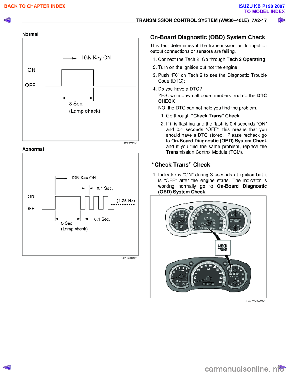
On-Board Diagnostic (OBD) System Check
This test determines if the transmission or its input or
output connections or sensors are failing.
1. Connect the Tech 2: Go through Tech 2 Operating.
2. Turn on the ignition but not the engine.
3. Push “F0” on Tech 2 to see the Diagnostic Trouble Code (DTC):
4. Do you have a DTC? YES: write down all code numbers and do the DTC
CHECK
NO: the DTC can not help you find the problem.
1. Go through “Check Trans” Check
2. If it is flashing and the flash is 0.4 seconds “ON”
and 0.4 seconds “OFF”, this means that you
should have a DTC stored. Please recheck go
to On-Board Diagnostic (OBD) System Chec
k
and if you find the same problem, replace the
Transmission Control Module (TCM).
“Check Trans” Check
1. Indicator is “ON” during 3 seconds at ignition but it
is “OFF” after the engine starts. The indicator is
working normally go to On-Board Diagnostic
(OBD) System Check .
RTW 77ASH000101
BACK TO CHAPTER INDEX
TO MODEL INDEX
ISUZU KB P190 2007