2007 ISUZU KB P190 engine mount
[x] Cancel search: engine mountPage 2440 of 6020
6E–270 ENGINE DRIVEABILITY AND EMISSIONS
FUEL PRESSURE RELIEF
Caution: To reduce the risk of fire and personal
injury, it is necessary to relieve the fuel system
pressure before servicing the fuel system
components.
Caution: After relieving the fuel system pressure, a
small amount of fuel may be released when
servicing fuel lines or connections. Reduce the
chance of personal injury by covering the fuel line
fitting with a short towel before disconnecting the
fittings. The towel will absorb any fuel that may leak
out. When the disconnect is completed, place the
towel in an approved container.
1. Remove the fuel filler cap.
2. Remove the fuel pump relay from the underhood relay box.
3. Start the engine and allow it to stall.
4. Crank the engine for about 30 seconds.
5. Disconnect the negative battery cable.
FUEL RAIL ASSEMBLY
Removal Procedure
NOTE:
• Use care when removing the fuel rail assembly in order to prevent damage to the injector al connector
terminal and the injector spray tips.
• Fitting should be capped and holes plugged during servicing to prevent dirt and other contaminants from
entering open lines and passage.
Important: An eight-digit identification number is
stamped on side of the fuel injector. Refer to this
number when you service the fuel rail or when a
replacement part is required.
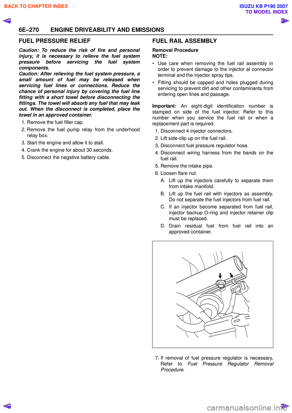
1. Disconnect 4 injector connectors.
2. Lift side-clip up on the fuel rail.
3. Disconnect fuel pressure regulator hose.
4. Disconnect wiring harness from the bands on the fuel rail.
5. Remove the intake pipe.
6. Loosen flare nut.
A. Lift up the injectors carefully to separate them from intake manifold.
B. Lift up the fuel rail with injectors as assembly. Do not separate the fuel injectors from fuel rail.
C. If an injector become separated from fuel rail, injector backup O-ring and injector retainer clip
must be replaced.
D. Drain residual fuel from fuel rail into an approved container.
7. If removal of fuel pressure regulator is necessary, Refer to Fuel Pressure Regulator Removal
Procedure .
BACK TO CHAPTER INDEX
TO MODEL INDEX
ISUZU KB P190 2007
Page 2443 of 6020
ENGINE DRIVEABILITY AND EMISSIONS 6E–273
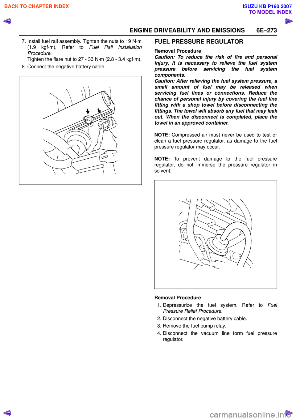
7. Install fuel rail assembly. Tighten the nuts to 19 N·m(1.9 kgf·m). Refer to Fuel Rail Installation
Procedure .
Tighten the flare nut to 27 - 33 N·m (2.8 - 3.4 kgf·m).
8. Connect the negative battery cable.FUEL PRESSURE REGULATOR
Removal Procedure
Caution: To reduce the risk of fire and personal
injury, it is necessary to relieve the fuel system
pressure before servicing the fuel system
components.
Caution: After relieving the fuel system pressure, a
small amount of fuel may be released when
servicing fuel lines or connections. Reduce the
chance of personal injury by covering the fuel line
fitting with a shop towel before disconnecting the
fittings. The towel will absorb any fuel that may leak
out. When the disconnect is completed, place the
towel in an approved container.
NOTE: Compressed air must never be used to test or
clean a fuel pressure regulator, as damage to the fuel
pressure regulator may occur.
NOTE: To prevent damage to the fuel pressure
regulator, do not immerse the pressure regulator in
solvent.
Removal Procedure
1. Depressurize the fuel system. Refer to Fuel
Pressure Relief Procedure.
2. Disconnect the negative battery cable.
3. Remove the fuel pump relay.
4. Disconnect the vacuum line form fuel pressure regulator.
BACK TO CHAPTER INDEX
TO MODEL INDEX
ISUZU KB P190 2007
Page 2470 of 6020
6G-6 ENGINE LUBRICATION
Oil Pan
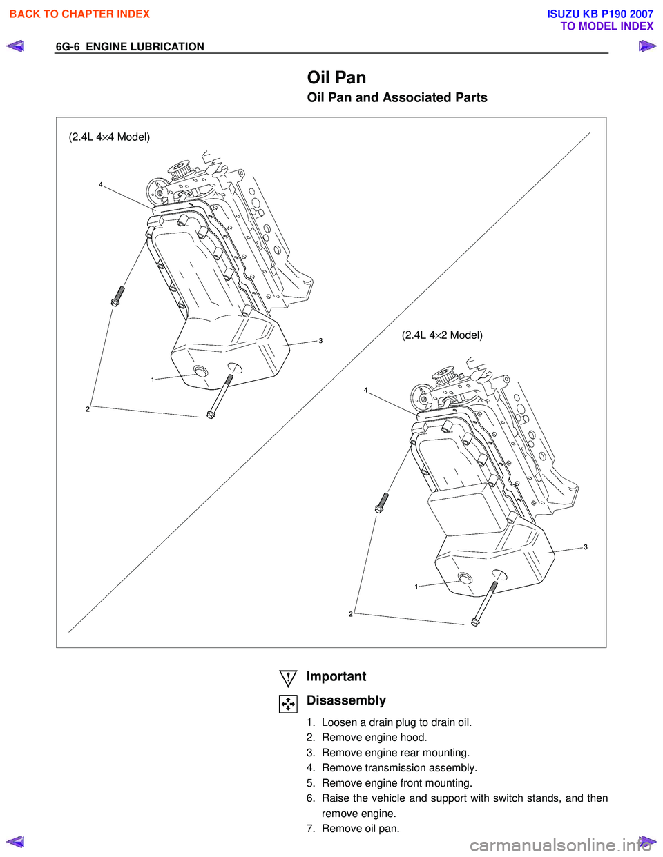
Oil Pan and Associated Parts
(2.4L 4×4 Model)
(2.4L 4×2 Model)
Important
Disassembly
1. Loosen a drain plug to drain oil.
2. Remove engine hood.
3. Remove engine rear mounting.
4. Remove transmission assembly.
5. Remove engine front mounting.
6. Raise the vehicle and support with switch stands, and then remove engine.
7. Remove oil pan.
BACK TO CHAPTER INDEX
TO MODEL INDEX
ISUZU KB P190 2007
Page 2484 of 6020
Engine Mechanical – V6 Page 6A1–5
Camshaft Visual Inspection ............................................................................................................................ 150
Camshaft Measurement ........................................................................................................... ...................... 151
Reinstall .............................................................................................................................................................. 153
Right-hand Side................................................................................................................ .............................. 153
Left-hand Side ................................................................................................................................................ 155
3.20 Rocker Arm..................................................................................................................... .................................... 158
Remove ............................................................................................................................................................... 158
Clean and Inspect .............................................................................................................. ................................ 158
Reinstall .............................................................................................................................................................. 159
3.21 Stationary Hydraulic Lash Adjuster ............................................................................................. .................... 160
Remove ............................................................................................................................................................... 160
Clean and Inspect .............................................................................................................. ................................ 160
Reinstall .............................................................................................................................................................. 161
3.22 Cylinder Head Assembly ......................................................................................................... .......................... 161
Remove ............................................................................................................................................................... 161
Right-hand Side (Bank 1) Cylinder Head ......................................................................................... .............. 161
Left-hand Side (Bank 2) Cylinder Head .......................................................................................................... 162
Disassemble ....................................................................................................................................................... 163
Clean ................................................................................................................................................................... 166
Inspect ................................................................................................................................................................ 167
Visual Inspection .............................................................................................................. .............................. 167
Cylinder Head Measurement...................................................................................................... .................... 167
Valve Spring Inspection and Measurement ........................................................................................ ............ 169
Valve and Seat Grinding ................................................................................................................................ 170
Assemble ............................................................................................................................................................ 174
Reinstall .............................................................................................................................................................. 177
Right-hand Side (Bank 1) Cylinder Head ......................................................................................... .............. 177
Left-hand Side (Bank 2) Cylinder Head .......................................................................................................... 178
3.23 Engine Mounts and Brackets ............................................................................................................................ 181
Remove .......................................................................................................................................................... 181
Engine Mount Location .......................................................................................................... ........................... 182
Inspect ................................................................................................................................................................ 182
Reinstall .............................................................................................................................................................. 183
4 Major Service Operations ....................................................................................................... ...........184
4.1 Engine Removal ................................................................................................................................................. 184
Remove .......................................................................................................................................................... 185
Disassemble................................................................................................................................................... 197
Reassemble ................................................................................................................................................... 198
Reinstall ......................................................................................................................................................... 198
4.2 Oil Pan and Oil Pump Suction Pipe Assembly ..................................................................................... ........... 198
Remove .......................................................................................................................................................... 198
Disassemble................................................................................................................................................... 200
Clean .............................................................................................................................................................. 200
Inspect............................................................................................................................................................ 201
Reassemble ................................................................................................................................................... 201
Reinstall ......................................................................................................................................................... 202
4.3 Flexplate Assembly ............................................................................................................. .............................. 203
Remove ............................................................................................................................................................... 203
Clean ................................................................................................................................................................... 204
Inspect ................................................................................................................................................................ 204
Reinstall ...................................................................................................................... ........................................ 205
4.4 Crankshaft Rear Seal and Plate Assembly ........................................................................................ .............. 205
Remove ............................................................................................................................................................... 205
Reinstall .............................................................................................................................................................. 207
4.5 Pistons, Pins, Rings, Connecting Rods and Big-end Bearings ..................................................................... 208
Remove ............................................................................................................................................................... 208
Disassemble ....................................................................................................................................................... 211
Clean and Inspect .............................................................................................................. ................................ 212
BACK TO CHAPTER INDEX
TO MODEL INDEX
ISUZU KB P190 2007
Page 2500 of 6020
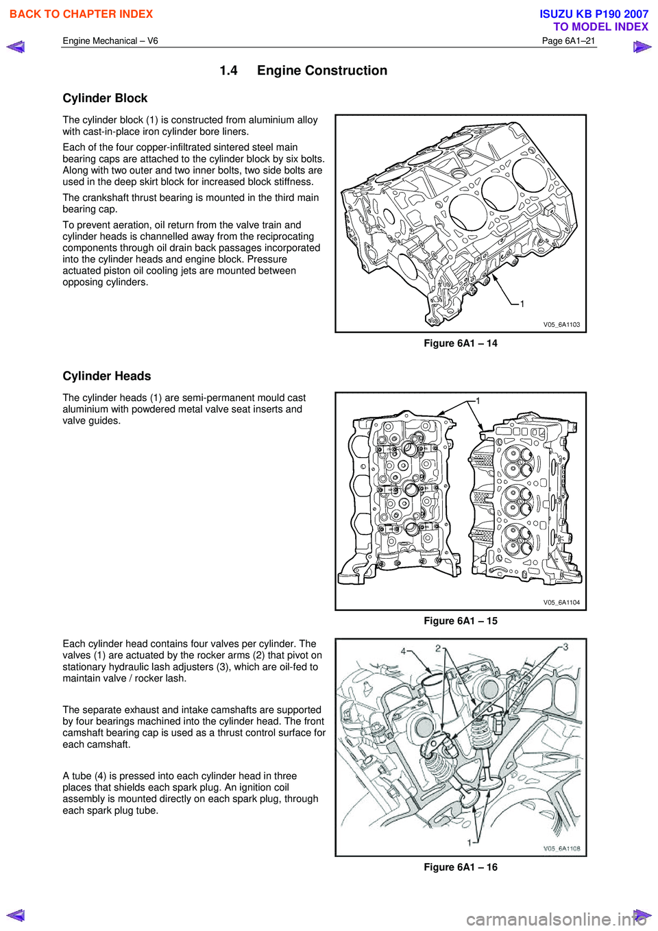
Engine Mechanical – V6 Page 6A1–21
1.4 Engine Construction
Cylinder Block
The cylinder block (1) is constructed from aluminium alloy
with cast-in-place iron cylinder bore liners.
Each of the four copper-infiltrated sintered steel main
bearing caps are attached to the cylinder block by six bolts.
Along with two outer and two inner bolts, two side bolts are
used in the deep skirt block for increased block stiffness.
The crankshaft thrust bearing is mounted in the third main
bearing cap.
To prevent aeration, oil return from the valve train and
cylinder heads is channelled away from the reciprocating
components through oil drain back passages incorporated
into the cylinder heads and engine block. Pressure
actuated piston oil cooling jets are mounted between
opposing cylinders.
Figure 6A1 – 14
Cylinder Heads
The cylinder heads (1) are semi-permanent mould cast
aluminium with powdered metal valve seat inserts and
valve guides.
Figure 6A1 – 15
Each cylinder head contains four valves per cylinder. The
valves (1) are actuated by the rocker arms (2) that pivot on
stationary hydraulic lash adjusters (3), which are oil-fed to
maintain valve / rocker lash.
The separate exhaust and intake camshafts are supported
by four bearings machined into the cylinder head. The front
camshaft bearing cap is used as a thrust control surface for
each camshaft.
A tube (4) is pressed into each cylinder head in three
places that shields each spark plug. An ignition coil
assembly is mounted directly on each spark plug, through
each spark plug tube.
Figure 6A1 – 16
BACK TO CHAPTER INDEX
TO MODEL INDEX
ISUZU KB P190 2007
Page 2503 of 6020
Engine Mechanical – V6 Page 6A1–24
1.5 Engine Lubrication System
Lubrication Description
A structural diecast aluminium oil pan is fitted that incorporates an oil suction pipe, an oil deflector and an oil level sensor.
The oil suction pipe is bolted into the oil pan and seals to the bottom of the cylinder block with a gasket. The oil deflector
is bolted to the upper portion of the oil pan and ensures oil supply is maintained under all conditions. The oil level sensor
is mounted through the bottom of the oil pan.
A crankshaft driven gerotor oil pump is mounted to the front of the cylinder block. The pump, which incorporates an
internal pressure-relief valve, draws oil from the oil suction tube through the lower passage in the cylinder block. Oil is
then directed through an upper passage to the left-hand side of the cylinder block where the oil filter adapter is mounted.
The oil filter adapter incorporates a top-access, cartridge style oil filter. The filter is accessed through a screw-on cap tha t
incorporates an oil bypass valve. The oil filter adapter housing incorporates a drain back control valve and a threaded oil
pressure sender. Oil flows through a lower passage within the oil filter adapter and through the oil filter cartridge. Filtered
oil travels back through the upper passage of the adapter and into the engine block.
Oil is then directed up and across the front of the cylinder block, through several drilled passages. These front passages
feed oil to each cylinder head, the passage for the main bearings and piston oil jets, the right-hand and left-hand
secondary idler sprockets and to the primary timing chain tensioner.
Each cylinder head passage directs oil into oiling circuits for the stationary hydraulic lash adjusters (SHLAs) and the
camshaft bearing journals. An additional passage in the cylinder head also directs oil to the secondary timing chain
tensioner.
The oil passage that supplies oil to the main bearings also supplies oil to pressure actuated piston cooling oil jets. Each
oil jet is mounted between opposing cylinder bores and directs oil to the two bores to provide extra cooling and control
piston temperatures.
From the front passages, oil is directed to the front of the block where the right-hand and left-hand intermediate drive
shaft sprockets and the primary timing chain tensioner are mounted. Each camshaft timing chain tensioner relies on a
gasket to maintain an oil reserve after the engine is turned off. All camshaft timing chain tensioners incorporate a small
oil jet to supply an oil spray onto the camshaft timing chain components.
Oil returns to the oil pan, either through the camshaft timing chain area or through the drain back passages on the
outboard walls of the cylinder heads and cylinder block.
1.6 Service Notes
Cleanliness and Care
Throughout this Section, correct cleaning and protection of machined surfaces and friction areas is a part of the repair
procedure. This is considered standard workshop practice, even if not specifically stated.
W hen any internal engine part is serviced, care and cleanliness is extremely important.
W hen components are removed for service, they should be marked, organised or retained in a specific order for
reassembly.
At the time of installation, components should be installed in the same location and with the same mating surface as
when removed.
Any engine is a combination of many machined, honed, polished and lapped surfaces with tolerances that are measured
in thousandths of a millimetre. These surfaces should be covered or protected to avoid component damage.
A liberal coating of clean engine oil should be applied to friction areas during assembly, as the lubrication will protect and
lubricate friction surfaces during the initial engine start-up.
Replacing Engine Gaskets
Re-Using Gaskets and Applying Sealants
• do not reuse any gasket unless specified,
• gaskets that can be reused will be identified in the service procedure, and
• do not apply sealant to any gasket or sealing surface unless specified in the service information.
Separating Components
• Use a rubber mallet to separate components.
• Bump the part sideways to loosen the components.
• Bumping should be done at bends or reinforced areas to prevent distortion of parts.
Cleaning Gasket Surfaces
• W here required, remove all gasket and sealing material from the part using a plastic or wood scraper.
• Care must be used to avoid gouging or scraping the sealing surfaces.
BACK TO CHAPTER INDEX
TO MODEL INDEX
ISUZU KB P190 2007
Page 2504 of 6020
Engine Mechanical – V6 Page 6A1–25
• Do not use any other method or technique to remove sealant or gasket material from a part.
• Do not use abrasive pads, sand paper, or power tools to clean the gasket surfaces as these methods of cleaning
can cause damage to the component sealing surfaces. Abrasive pads also produce fine grit that the oil filter cannot
remove from the oil. This grit is abrasive and has been known to cause internal engine damage.
Assembling Components
• W hen assembling components, use only the sealant specified or equivalent in the service procedure.
• Sealing surfaces should be clean and free of debris or oil.
• Specific components such as crankshaft oil seals or valve stem oil seals may require lubrication during assembly.
• Components requiring lubrication will be identified in the service procedure.
• W hen applying sealant to a component, apply the amount specified in the service procedure.
• Do not allow the sealant to enter into any blind threaded holes as it may prevent the bolt from clamping correctly or
cause component damage when tightened.
• Only ever tighten bolts to the correct torque specification. Do not over-tighten.
Use of Room Temperature Vulcanising and Anaerobic Sealer
CAUTION
A number of sealant types are commonly
used in engines. Examples are; room
temperature vulcanising (RTV) sealer,
anaerobic gasket eliminator sealer, and
anaerobic thread sealant and pipe joint
compound. The correct type of sealant and
amount must be used in the specified location
to prevent oil leaks. Do not interchange the
different types of sealers.
Room Temperature Vulcanising Sealer
• Room temperature vulcanising (RTV) sealant hardens when exposed to air. This type of sealer is used where two
non-rigid parts (such as the intake manifold and the engine block) are assembled together.
• Do not use RTV sealant in areas where extreme temperatures are experienced. These areas include the exhaust
manifold, head gasket, or other surfaces where a gasket eliminator is specified.
• Follow all safety recommendations and directions that are on the container.
• To remove the sealant or the gasket material, refer to Replacing Engine Gaskets.
• Apply RTV to a clean surface. Use a bead size as specified in the service procedure. Run the bead to the inside of
any bolt holes. Do not allow the sealer to enter any blind threaded holes, as it may prevent the bolt from clamping
correctly or cause damage when the bolt is tightened.
• Assemble components while RTV is still wet (within 3 minutes). Do not wait for RTV to skin over.
• Tighten the bolts to the correct torque specification. Do not over-tighten.
Anaerobic Sealer
• Anaerobic gasket eliminator or thread sealant, hardens in the absence of air. This type sealer is used where two
rigid parts (such as castings) are assembled together, where fasteners are subjected to vibration, or where the
holes are not blind. W hen two rigid parts are disassembled and no sealer or gasket is readily noticeable, the parts
were probably assembled using a gasket eliminator.
• Follow all safety recommendations and directions that are on the container.
• To remove the sealant or the gasket material, refer to Replacing Engine Gaskets.
• Apply a continuous bead of gasket eliminator to one flange or on the bolt/stud thread. All surfaces must be clean
and dry.
• Spread the sealer evenly to achieve a uniform coating on the sealing surface.
• Do not allow the sealer to enter any blind threaded holes as it may prevent the bolt from clamping correctly or
cause damage when tightened.
BACK TO CHAPTER INDEX
TO MODEL INDEX
ISUZU KB P190 2007
Page 2519 of 6020
Engine Mechanical – V6 Page 6A1–40
Cause Correction
W orn valve guides and or valve stems. Inspect and repair valves and valve guides as required,
refer to 3.22 Cylinder Head Assembly.
W orn or damaged valve stem oil seal. Replace valve stem oil seals as required, refer to 3.22
Cylinder Head Assembly.
Piston rings broken, worn or not seated correctly. Allowing adequate time for the piston rings to seat correctly,
replace piston rings as required, refer to 4.5 Pistons, Pins,
Rings, Connecting Rods and Big-end Bearings.
Piston rings incorrectly installed or not matched to cylinder
bore oversize. Replace piston rings as required, refer to 4.5 Pistons, Pins,
Rings, Connecting Rods and Big-end Bearings.
2.18 Engine Oil Leak Diagnosis
Introduction
It is important to correctly identify the source of an engine oil leak. For example, a power steering fluid leak or spillage
during servicing can travel across the valley area of the engine and run-out the weep hole, which is located at the back of
the cylinder block. Failure to correctly identify the source of an engine oil leak can lead to unnecessary replacement of
engine components.
Most fluid leaks can be repaired by repairing or replacing the faulty component or resealing the gasket surface. However,
once a leak is identified it is important to determine and repair the cause as well as the leak itself.
Locating and Identifying the Leak
Inspect the leaking fluid and determine whether it is engine oil, transmission fluid, power steering fluid, brake fluid or
some other fluid. If unsure of the source of the leaking lubricant, a quick check of fluid levels should indicate where the
fluid is coming from, as one or more fluid level should be low.
Visual Inspection
Once the type of leaking fluid has been determined, a visual inspection of the affected system should be performed.
W hen performing the visual inspection:
1 Bring the vehicle to the normal operating temperature.
2 Park the vehicle over a large sheet of paper or other clean surface.
3 Leave the vehicle idling for 2-3 minutes, then check for dripping fluid.
4 If required, identify the type of fluid leaking and the approximate location of the leak.
5 Visually inspect the suspected area. A small mirror may assist viewing areas that are difficult to see normally.
6 Check for leaks at all sealing surfaces and fittings.
7 Check for any cracked or damaged components.
8 If the leak cannot be located, completely clean the entire engine and surrounding components, drive the vehicle at normal operating temperature for several kilometres and then repeat Steps 3 to 8.
9 If the leak still cannot be located, proceed with either the Powder Method or Black Light and Dye Method as outlined below.
Powder Method
1 Completely clean the entire engine and surrounding components.
2 Apply an aerosol type powder (e.g. foot powder) to the suspected area.
3 Operate the vehicle at normal operating temperature and at varying speeds for several kilometres.
4 Identify the source of the leak from the discoloration of the powder around the suspect components.
5 If required, use a small mirror to assist in viewing areas that are difficult to see normally.
6 Refer to Possible Causes for Engine Oil Leaks in this Section, and repair or replace components as required.
Black Light and Dye Method
A black light and die kit Tool No. J28428-E or a commercially available equivalent is available to technicians to aid in
engine oil leak diagnosis. W hen using a black light and die kit for the first time, it is recommended the technician read the
manufacturers instructions prior to using the kit.
1 Add the specified amount of dye, as per manufacturers instructions, into the engine or suspected source of the oil leak.
2 Operate the vehicle at normal operating temperature and at varying speeds for several kilometres.
BACK TO CHAPTER INDEX
TO MODEL INDEX
ISUZU KB P190 2007