Page 2598 of 6020
Engine Mechanical – V6 Page 6A1–119
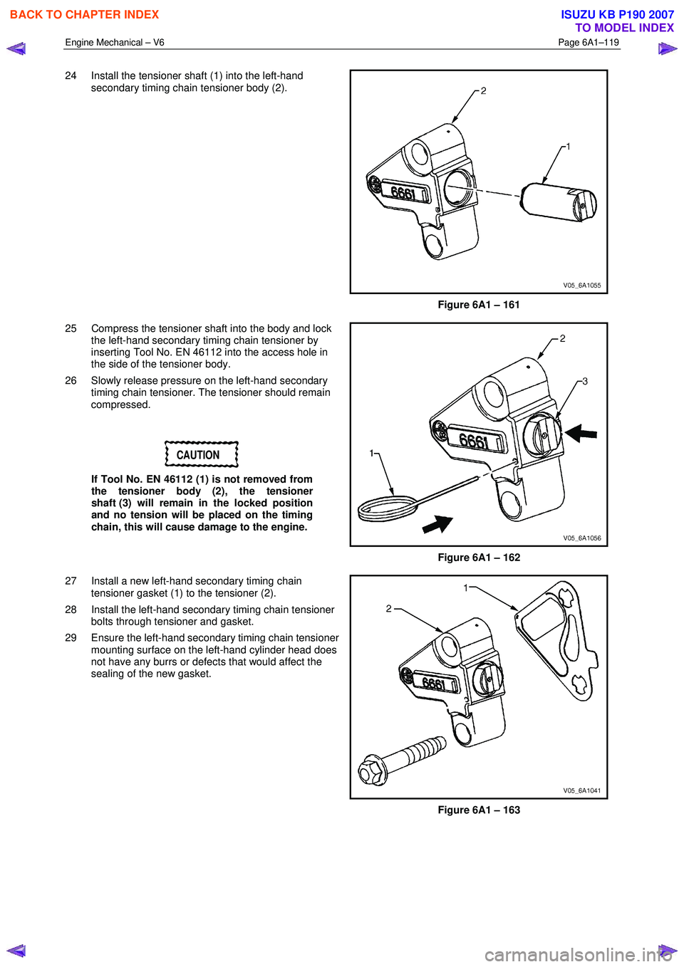
24 Install the tensioner shaft (1) into the left-hand
secondary timing chain tensioner body (2).
Figure 6A1 – 161
25 Compress the tensioner shaft into the body and lock the left-hand secondary timing chain tensioner by
inserting Tool No. EN 46112 into the access hole in
the side of the tensioner body.
26 Slowly release pressure on the left-hand secondary timing chain tensioner. The tensioner should remain
compressed.
CAUTION
If Tool No. EN 46112 (1) is not removed from
the tensioner body (2), the tensioner
shaft (3) will remain in the locked position
and no tension will be placed on the timing
chain, this will cause damage to the engine.
Figure 6A1 – 162
27 Install a new left-hand secondary timing chain tensioner gasket (1) to the tensioner (2).
28 Install the left-hand secondary timing chain tensioner bolts through tensioner and gasket.
29 Ensure the left-hand secondary timing chain tensioner mounting surface on the left-hand cylinder head does
not have any burrs or defects that would affect the
sealing of the new gasket.
Figure 6A1 – 163
BACK TO CHAPTER INDEX
TO MODEL INDEX
ISUZU KB P190 2007
Page 2605 of 6020
Engine Mechanical – V6 Page 6A1–126
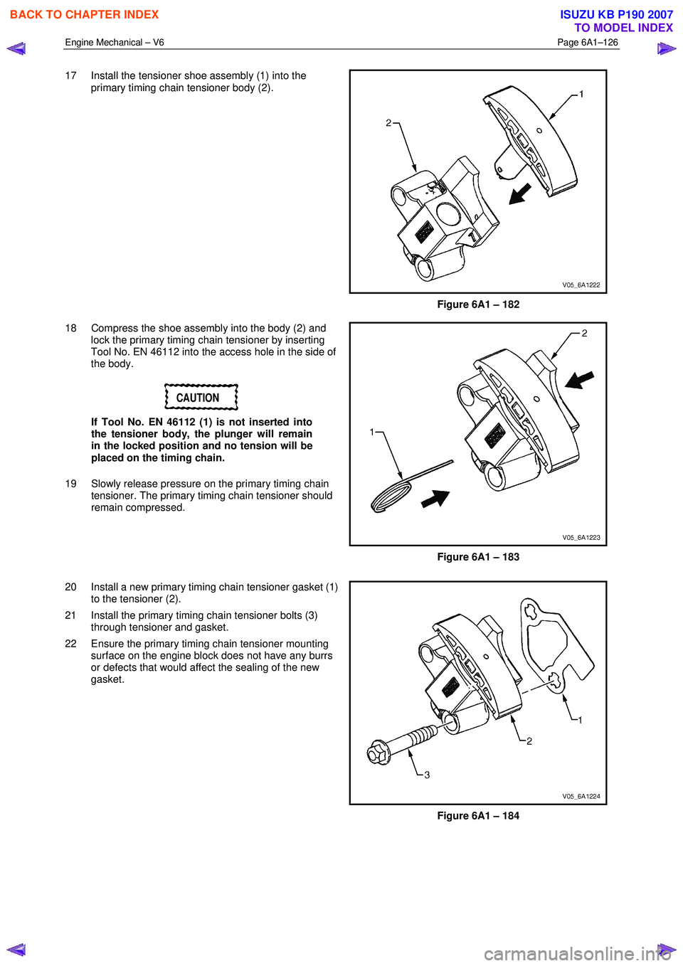
17 Install the tensioner shoe assembly (1) into the
primary timing chain tensioner body (2).
Figure 6A1 – 182
18 Compress the shoe assembly into the body (2) and lock the primary timing chain tensioner by inserting
Tool No. EN 46112 into the access hole in the side of
the body.
CAUTION
If Tool No. EN 46112 (1) is not inserted into
the tensioner body, the plunger will remain
in the locked position and no tension will be
placed on the timing chain.
19 Slowly release pressure on the primary timing chain tensioner. The primary timing chain tensioner should
remain compressed.
Figure 6A1 – 183
20 Install a new primary timing chain tensioner gasket (1) to the tensioner (2).
21 Install the primary timing chain tensioner bolts (3) through tensioner and gasket.
22 Ensure the primary timing chain tensioner mounting surface on the engine block does not have any burrs
or defects that would affect the sealing of the new
gasket.
Figure 6A1 – 184
BACK TO CHAPTER INDEX
TO MODEL INDEX
ISUZU KB P190 2007
Page 2613 of 6020
Engine Mechanical – V6 Page 6A1–134
18 Install the tensioner shaft (1) into the right-hand
secondary timing chain tensioner body (2).
Figure 6A1 – 205
19 Compress the tensioner shaft into the body and lock the tensioner by inserting Tool No. EN 46112 into the
access hole in the side of the tensioner body.
20 Slowly release pressure on the right-hand secondary timing chain tensioner. The tensioner should remain
compressed.
Figure 6A1 – 206
21 Install a new right-hand secondary timing chain tensioner gasket (1) to the tensioner (2).
22 Install the right-hand secondary timing chain tensioner bolts (3) through the tensioner and gasket.
23 Ensure the right-hand secondary timing chain tensioner mounting surface on the right-hand cylinder
head does not have any burrs or defects that would
affect the sealing of the new tensioner gasket.
Figure 6A1 – 207
BACK TO CHAPTER INDEX
TO MODEL INDEX
ISUZU KB P190 2007
Page 2620 of 6020
Engine Mechanical – V6 Page 6A1–141
Reassemble
CAUTION
As there are no serviceable components
within the oil pump, a disassembled oil pump
must be replaced.
Reinstall
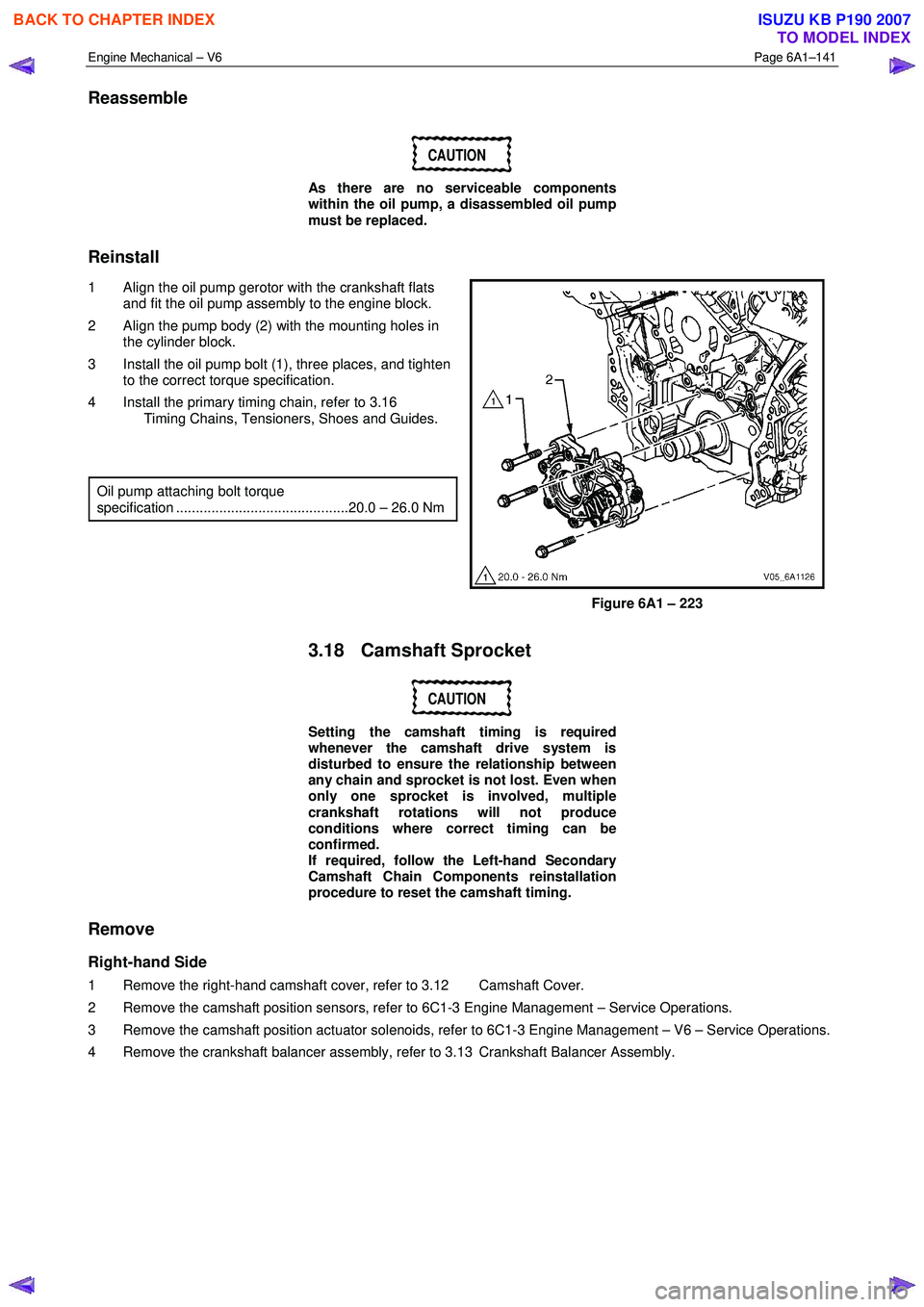
1 Align the oil pump gerotor with the crankshaft flats and fit the oil pump assembly to the engine block.
2 Align the pump body (2) with the mounting holes in the cylinder block.
3 Install the oil pump bolt (1), three places, and tighten to the correct torque specification.
4 Install the primary timing chain, refer to 3.16 Timing Chains, Tensioners, Shoes and Guides.
Oil pump attaching bolt torque
specification ............................................20.0 – 26.0 Nm
Figure 6A1 – 223
3.18 Camshaft Sprocket
CAUTION
Setting the camshaft timing is required
whenever the camshaft drive system is
disturbed to ensure the relationship between
any chain and sprocket is not lost. Even when
only one sprocket is involved, multiple
crankshaft rotations will not produce
conditions where correct timing can be
confirmed.
If required, follow the Left-hand Secondary
Camshaft Chain Components reinstallation
procedure to reset the camshaft timing.
Remove
Right-hand Side
1 Remove the right-hand camshaft cover, refer to 3.12 Camshaft Cover.
2 Remove the camshaft position sensors, refer to 6C1-3 Engine Management – Service Operations.
3 Remove the camshaft position actuator solenoids, refer to 6C1-3 Engine Management – V6 – Service Operations.
4 Remove the crankshaft balancer assembly, refer to 3.13 Crankshaft Balancer Assembly.
BACK TO CHAPTER INDEX
TO MODEL INDEX
ISUZU KB P190 2007
Page 2632 of 6020
Engine Mechanical – V6 Page 6A1–153
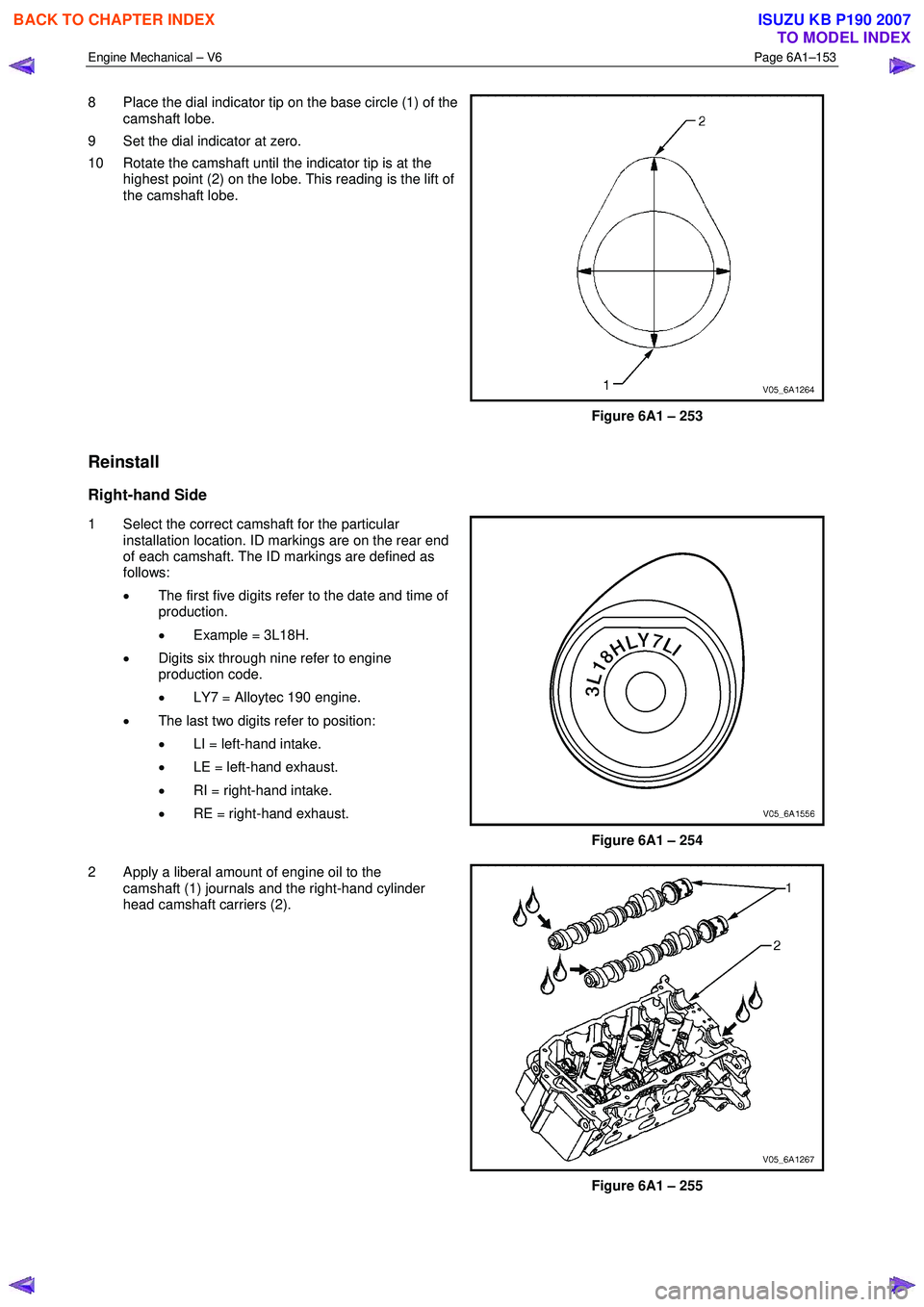
8 Place the dial indicator tip on the base circle (1) of the
camshaft lobe.
9 Set the dial indicator at zero.
10 Rotate the camshaft until the indicator tip is at the highest point (2) on the lobe. This reading is the lift of
the camshaft lobe.
Figure 6A1 – 253
Reinstall
Right-hand Side
1 Select the correct camshaft for the particular installation location. ID markings are on the rear end
of each camshaft. The ID markings are defined as
follows:
• The first five digits refer to the date and time of
production.
• Example = 3L18H.
• Digits six through nine refer to engine
production code.
• LY7 = Alloytec 190 engine.
• The last two digits refer to position:
• LI = left-hand intake.
• LE = left-hand exhaust.
• RI = right-hand intake.
• RE = right-hand exhaust.
Figure 6A1 – 254
2 Apply a liberal amount of engine oil to the camshaft (1) journals and the right-hand cylinder
head camshaft carriers (2).
Figure 6A1 – 255
BACK TO CHAPTER INDEX
TO MODEL INDEX
ISUZU KB P190 2007
Page 2633 of 6020
Engine Mechanical – V6 Page 6A1–154
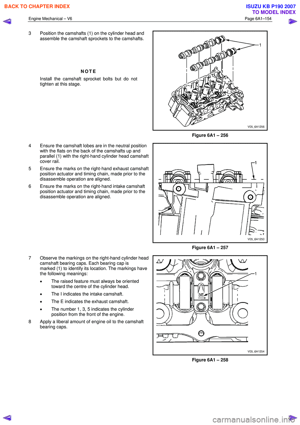
3 Position the camshafts (1) on the cylinder head and
assemble the camshaft sprockets to the camshafts.
NOTE
Install the camshaft sprocket bolts but do not
tighten at this stage.
Figure 6A1 – 256
4 Ensure the camshaft lobes are in the neutral position with the flats on the back of the camshafts up and
parallel (1) with the right-hand cylinder head camshaft
cover rail.
5 Ensure the marks on the right-hand exhaust camshaft position actuator and timing chain, made prior to the
disassemble operation are aligned.
6 Ensure the marks on the right-hand intake camshaft position actuator and timing chain, made prior to the
disassemble operation are aligned.
Figure 6A1 – 257
7 Observe the markings on the right-hand cylinder head camshaft bearing caps. Each bearing cap is
marked (1) to identify its location. The markings have
the following meanings:
• The raised feature must always be oriented
toward the centre of the cylinder head.
• The I indicates the intake camshaft.
• The E indicates the exhaust camshaft.
• The number 1, 3, 5 indicates the cylinder
position from the front of the engine.
8 Apply a liberal amount of engine oil to the camshaft bearing caps.
Figure 6A1 – 258
BACK TO CHAPTER INDEX
TO MODEL INDEX
ISUZU KB P190 2007
Page 2635 of 6020
Engine Mechanical – V6 Page 6A1–156
2 Apply a liberal amount of engine oil to the camshaft
journals and the left-hand cylinder head camshaft
carriers.
Figure 6A1 – 262
3 Position the camshafts (1) on the cylinder head and assemble the camshaft sprockets to the camshafts.
NOTE
Install the camshaft sprocket bolts but do not
tighten at this stage.
Figure 6A1 – 263
4 Ensure the camshaft lobes are in the neutral position with the flats on the back of the camshafts up and
parallel (1) with the left-hand cylinder head camshaft
cover rail.
5 Ensure the marks on the left-hand exhaust camshaft position actuator and timing chain, made prior to the
disassemble operation are aligned.
6 Ensure the marks on the left-hand intake camshaft position actuator and timing chain, made prior to the
disassemble operation are aligned.
Figure 6A1 – 264
BACK TO CHAPTER INDEX
TO MODEL INDEX
ISUZU KB P190 2007
Page 2636 of 6020
Engine Mechanical – V6 Page 6A1–157
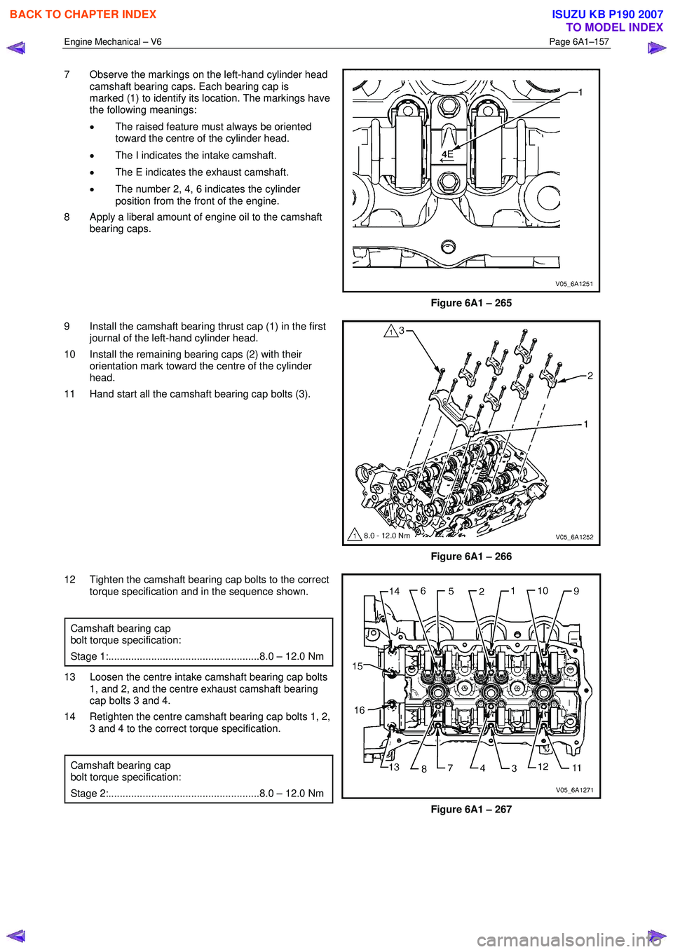
7 Observe the markings on the left-hand cylinder head
camshaft bearing caps. Each bearing cap is
marked (1) to identify its location. The markings have
the following meanings:
• The raised feature must always be oriented
toward the centre of the cylinder head.
• The I indicates the intake camshaft.
• The E indicates the exhaust camshaft.
• The number 2, 4, 6 indicates the cylinder
position from the front of the engine.
8 Apply a liberal amount of engine oil to the camshaft bearing caps.
Figure 6A1 – 265
9 Install the camshaft bearing thrust cap (1) in the first journal of the left-hand cylinder head.
10 Install the remaining bearing caps (2) with their orientation mark toward the centre of the cylinder
head.
11 Hand start all the camshaft bearing cap bolts (3).
Figure 6A1 – 266
12 Tighten the camshaft bearing cap bolts to the correct torque specification and in the sequence shown.
Camshaft bearing cap
bolt torque specification:
Stage 1:.....................................................8.0 – 12.0 Nm
13 Loosen the centre intake camshaft bearing cap bolts 1, and 2, and the centre exhaust camshaft bearing
cap bolts 3 and 4.
14 Retighten the centre camshaft bearing cap bolts 1, 2, 3 and 4 to the correct torque specification.
Camshaft bearing cap
bolt torque specification:
Stage 2:.....................................................8.0 – 12.0 Nm
Figure 6A1 – 267
BACK TO CHAPTER INDEX
TO MODEL INDEX
ISUZU KB P190 2007