2007 ISUZU KB P190 engine mount
[x] Cancel search: engine mountPage 2522 of 6020
Engine Mechanical – V6 Page 6A1–43
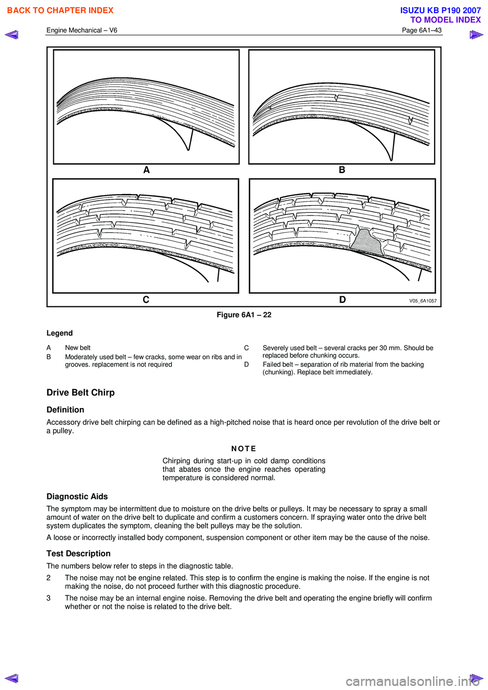
Figure 6A1 – 22
Legend
A New belt
B Moderately used belt – few cra cks, some wear on ribs and in
grooves. replacement is not required C Severely used belt – several cracks per 30 mm. S
hould be
replaced before chunking occurs.
D Failed belt – separation of rib material from the backing (chunking). Replace belt immediately.
Drive Belt Chirp
Definition
Accessory drive belt chirping can be defined as a high-pitched noise that is heard once per revolution of the drive belt or
a pulley.
NOTE
Chirping during start-up in cold damp conditions
that abates once the engine reaches operating
temperature is considered normal.
Diagnostic Aids
The symptom may be intermittent due to moisture on the drive belts or pulleys. It may be necessary to spray a small
amount of water on the drive belt to duplicate and confirm a customers concern. If spraying water onto the drive belt
system duplicates the symptom, cleaning the belt pulleys may be the solution.
A loose or incorrectly installed body component, suspension component or other item may be the cause of the noise.
Test Description
The numbers below refer to steps in the diagnostic table.
2 The noise may not be engine related. This step is to confirm the engine is making the noise. If the engine is not making the noise, do not proceed further with this diagnostic procedure.
3 The noise may be an internal engine noise. Removing the drive belt and operating the engine briefly will confirm whether or not the noise is related to the drive belt.
BACK TO CHAPTER INDEX
TO MODEL INDEX
ISUZU KB P190 2007
Page 2523 of 6020
Engine Mechanical – V6 Page 6A1–44
CAUTION
When running the engine with the accessory
drive belt removed, the coolant pump will not
be operating and the engine may overheat if
left unsupervised even for a short period.
NOTE
There may also be a number of DTCs set when
running the engine with the accessory drive belt
removed.
4 Inspect all drive pump pulleys for pilling. NOTE
Pilling is the small balls (pills) or strings of rubber
in the belt grooves caused by the accumulation of
rubber dust.
6 Misalignment of the accessory drive system pulleys may be caused by incorrect mounting of an accessory drive component (A/C compressor, generator etc.) or pulley. Misalignment may also be caused by incorrect installation of
a pulley during a previous repair. Test for a misaligned pulley using a straight edge in the pulley grooves across
two or three pulleys. If a misaligned pulley is found, refer to the relevant component service information for the
correct installation and removal procedures.
10 Inspecting the fasteners can eliminate the possibility that an incorrect fastener has been installed.
12 Inspecting the pulleys for being bent should include inspecting for a dent or other damage that would prevent the drive belt from not seating correctly in all of the pulley grooves or on the smooth surface when the back end of the
belt is used as the driving surface.
14 Replacing the drive belt when it is not damaged and there is no excessive pilling will only be a temporary repair.
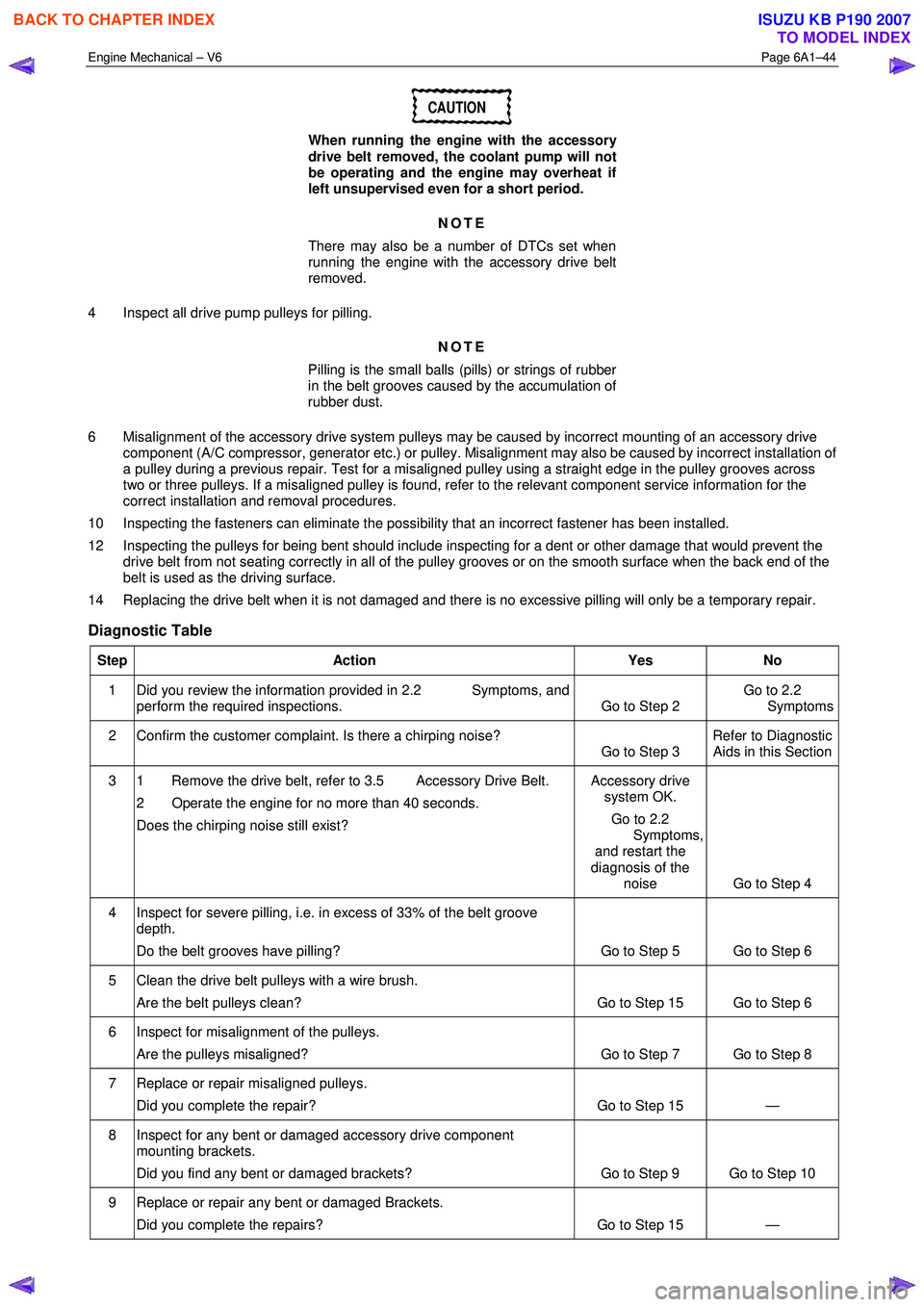
Diagnostic Table
Step Action Yes No
1 Did you review the information provided in 2.2 Symptoms, and
perform the required inspections. Go to Step 2 Go to 2.2
Symptoms
2 Confirm the customer complaint. Is there a chirping noise? Go to Step 3 Refer to Diagnostic
Aids in this Section
3 1 Remove the drive belt, refer to 3.5 Accessory Drive Belt.
2 Operate the engine for no more than 40 seconds.
Does the chirping noise still exist? Accessory drive
system OK.
Go to 2.2
Symptoms, and restart the
diagnosis of the noise Go to Step 4
4 Inspect for severe pilling, i.e. in excess of 33% of the belt groove
depth.
Do the belt grooves have pilling? Go to Step 5 Go to Step 6
5 Clean the drive belt pulleys with a wire brush. Are the belt pulleys clean? Go to Step 15 Go to Step 6
6 Inspect for misalignment of the pulleys. Are the pulleys misaligned? Go to Step 7 Go to Step 8
7 Replace or repair misaligned pulleys. Did you complete the repair? Go to Step 15 —
8 Inspect for any bent or damaged accessory drive component mounting brackets.
Did you find any bent or damaged brackets? Go to Step 9 Go to Step 10
9 Replace or repair any bent or damaged Brackets. Did you complete the repairs? Go to Step 15 —
BACK TO CHAPTER INDEX
TO MODEL INDEX
ISUZU KB P190 2007
Page 2525 of 6020
Engine Mechanical – V6 Page 6A1–46
7 Misalignment of the pulleys may be caused by one of the following:
• Incorrect mounting of an accessory drive component,
• Incorrect installation of an accessory drive pulley or,
• Bent or damaged pulley.
Test for a misaligned pulley using a straight edge in the pulley grooves across 2 or 3 pulleys. If a misaligned pulley is found, refer to the relevant component service information for the correct installation and removal procedures.
8 This test is to confirm the pulleys are the correct diameter and/or width. Using a known good vehicle, compare the pulley sizes.
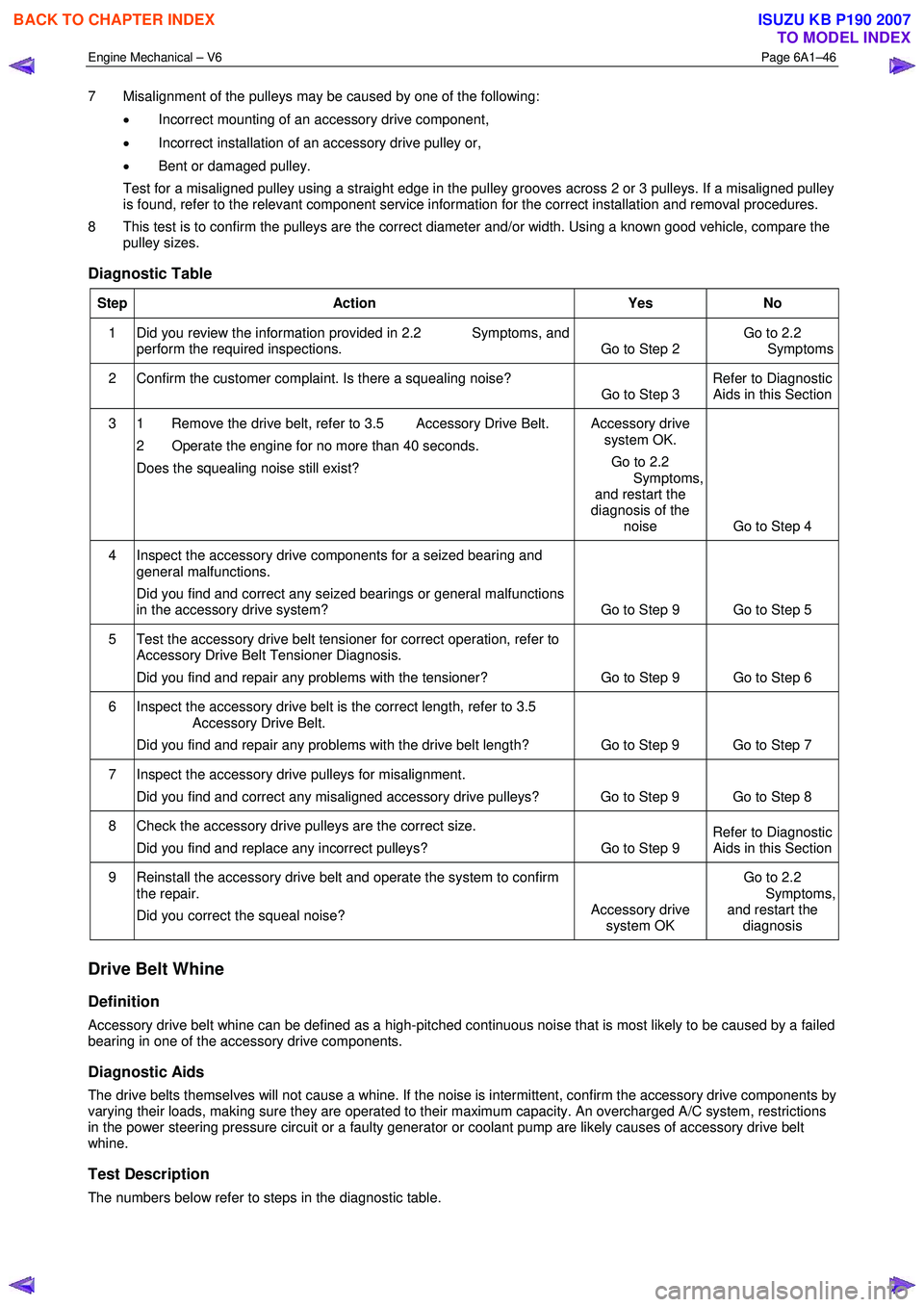
Diagnostic Table
Step Action Yes No
1 Did you review the information provided in 2.2 Symptoms, and
perform the required inspections. Go to Step 2 Go to 2.2
Symptoms
2 Confirm the customer complaint. Is there a squealing noise? Go to Step 3 Refer to Diagnostic
Aids in this Section
3 1 Remove the drive belt, refer to 3.5 Accessory Drive Belt.
2 Operate the engine for no more than 40 seconds.
Does the squealing noise still exist? Accessory drive
system OK.
Go to 2.2
Symptoms, and restart the
diagnosis of the noise Go to Step 4
4 Inspect the accessory drive components for a seized bearing and
general malfunctions.
Did you find and correct any seized bearings or general malfunctions
in the accessory drive system? Go to Step 9 Go to Step 5
5 Test the accessory drive belt tensioner for correct operation, refer to
Accessory Drive Belt Tensioner Diagnosis.
Did you find and repair any problems with the tensioner? Go to Step 9 Go to Step 6
6 Inspect the accessory drive belt is the correct length, refer to 3.5
Accessory Drive Belt.
Did you find and repair any problems with the drive belt length? Go to Step 9 Go to Step 7
7 Inspect the accessory drive pulleys for misalignment.
Did you find and correct any misaligned accessory drive pulleys? Go to Step 9 Go to Step 8
8 Check the accessory drive pulleys are the correct size. Did you find and replace any incorrect pulleys? Go to Step 9 Refer to Diagnostic
Aids in this Section
9 Reinstall the accessory drive belt and operate the system to confirm
the repair.
Did you correct the squeal noise? Accessory drive
system OK Go to 2.2
Symptoms, and restart the diagnosis
Drive Belt Whine
Definition
Accessory drive belt whine can be defined as a high-pitched continuous noise that is most likely to be caused by a failed
bearing in one of the accessory drive components.
Diagnostic Aids
The drive belts themselves will not cause a whine. If the noise is intermittent, confirm the accessory drive components by
varying their loads, making sure they are operated to their maximum capacity. An overcharged A/C system, restrictions
in the power steering pressure circuit or a faulty generator or coolant pump are likely causes of accessory drive belt
whine.
Test Description
The numbers below refer to steps in the diagnostic table.
BACK TO CHAPTER INDEX
TO MODEL INDEX
ISUZU KB P190 2007
Page 2527 of 6020
Engine Mechanical – V6 Page 6A1–48
NOTE
Pilling is the small balls (pills) or strings of rubber
in the belt grooves caused by the accumulation of
rubber dust.
Diagnostic Aids
Vibration from the engine may cause a body component or other parts to emit a rumbling noise.
The drive belt may have a condition that cannot be seen or felt. Sometimes the replacement of the belt may be the only
way to confirm the belt is faulty.
If the drive belt has been replaced and the diagnostic table completed, but the rumble is still present only when the drive
belt is installed, an accessory drive component such as the A/C compressor may be the cause. Varying the load to each
accessory drive component in turn, should help isolate which component is causing the noise.
Test Description
The numbers below refer to steps in the diagnostic table.
2 Confirms the symptom exists at the time of diagnosis. Other vehicle components may be causing the noise.
3 Confirms the accessory drive belt is the cause of the noise. Drive belt rumbling is often confused with an internal engine noise due to the similarity in the description. Removing the drive belt and operating the engine briefly will
confirm whether or not the noise is related to the drive belt.
CAUTION
When running the engine with the accessory
drive belt removed, the coolant pump will not
be operating and the engine may overheat if
left unsupervised even for a short period.
NOTE
There may also be a number of DTCs set when
running the engine with the accessory drive belt
removed.
4 Inspecting the drive belt is to ensure that it is not causing the noise. Small cracks across the ribs of the drive belt will not cause the noise and are not justification alone to replace the belt. Belt separation can be identified by the
ply of the belt separating and may be seen at the edge of the belt or felt as lumps under the belt.
5 Small amounts of pilling is a normal condition and is deemed acceptable. W hen the pilling is severe (33% of the belt groove depth), the belt does not have a smooth surface to run on and should be replaced.
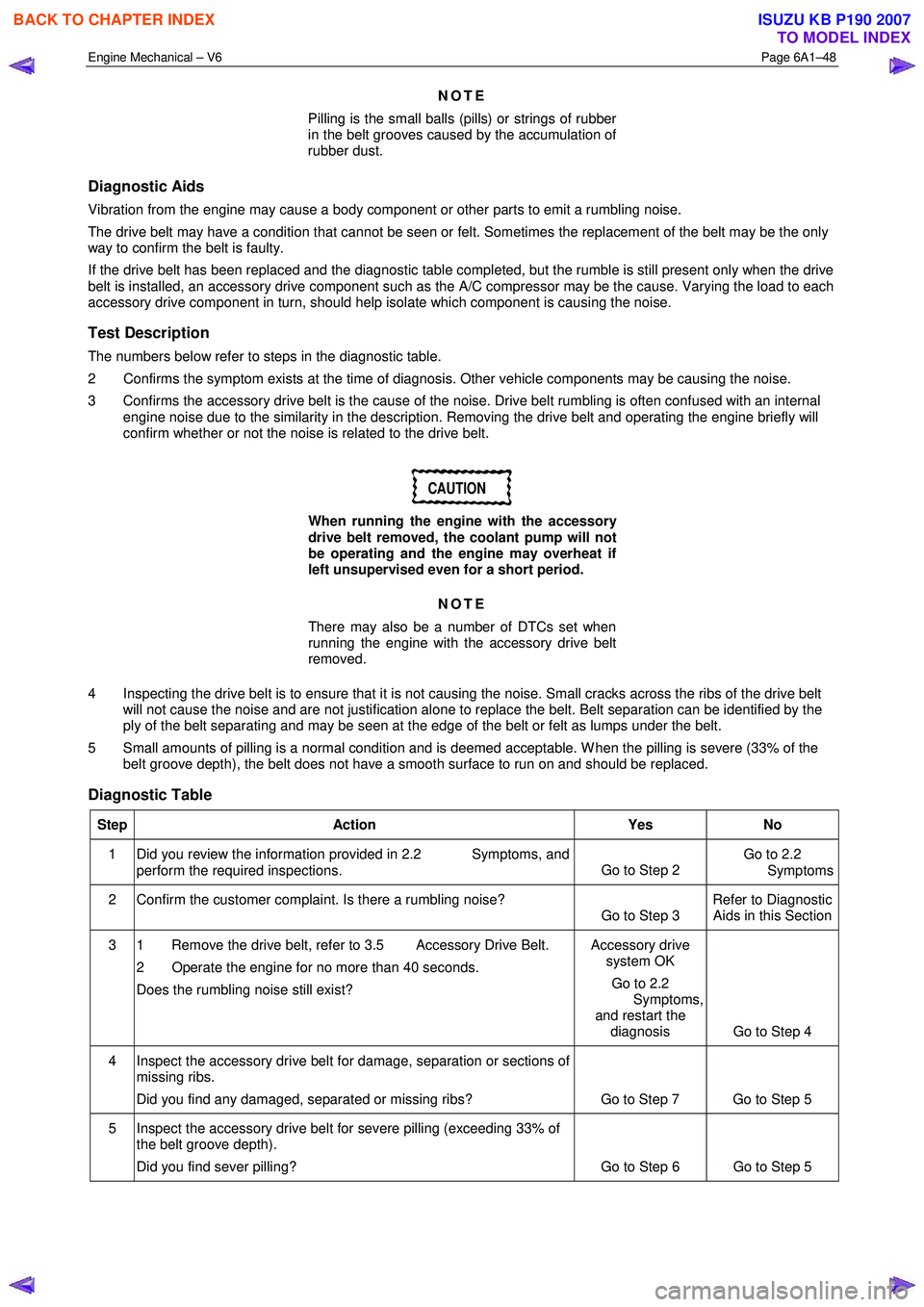
Diagnostic Table
Step Action Yes No
1 Did you review the information provided in 2.2 Symptoms, and
perform the required inspections. Go to Step 2 Go to 2.2
Symptoms
2 Confirm the customer complaint. Is there a rumbling noise? Go to Step 3 Refer to Diagnostic
Aids in this Section
3 1 Remove the drive belt, refer to 3.5 Accessory Drive Belt.
2 Operate the engine for no more than 40 seconds.
Does the rumbling noise still exist? Accessory drive
system OK
Go to 2.2
Symptoms,
and restart the diagnosis Go to Step 4
4 Inspect the accessory drive belt for damage, separation or sections of missing ribs.
Did you find any damaged, separated or missing ribs? Go to Step 7 Go to Step 5
5 Inspect the accessory drive belt for severe pilling (exceeding 33% of the belt groove depth).
Did you find sever pilling? Go to Step 6 Go to Step 5
BACK TO CHAPTER INDEX
TO MODEL INDEX
ISUZU KB P190 2007
Page 2529 of 6020

Engine Mechanical – V6 Page 6A1–50
Diagnostic Table
Step Action Yes No
1 Did you review the information provided in 2.2 Symptoms, and
perform the required inspections. Go to Step 2 Go to 2.2
Symptoms
2 Confirm the customer complaint. Is there a rumbling noise? Go to Step 3 Refer to Diagnostic
Aids in this Section
3 1 Remove the drive belt, refer to 3.5 Accessory Drive Belt.
2 Operate the engine for no more than 40 seconds.
Does the vibration noise still exist? Accessory drive
system OK.
Go to 4.2
Symptoms, and
restart the diagnosis Go to Step 4
4 Inspect the accessory drive belt for damage, wear, debris build-up or
sections of missing ribs.
Did you find any damage, wear, debris build-up or missing ribs? Go to Step 5 Go to Step 6
5 Install a new accessory drive belt, refer to 3.5 Accessory Drive Belt.
Did you replace the accessory drive belt? Go to Step 10 —
6 Inspect for incorrect, loose, missing or damaged fasteners. Did you find any incorrect, loose, missing or damaged fasteners? Go to Step 7 Go to Step 8
7 Tighten any loose fasteners to the correct torque specification, refer to
6 Torque W rench Specifications.
Replace any incorrect or missing fasteners.
Did you complete the repairs? Go to Step 10 —
8 Inspect the coolant pump for a bent shaft, refer to 6B1 Engine Cooling – V6.
Did you find and repair a bent coolant pump shaft? Go to Step 10 Go to Step 9
9 Inspect for bent, cracked or damaged accessory drive component mounting brackets.
Did you find and repair any bent brackets? Go to Step 10 Refer to Diagnostic
Aids in this Section
10 If required, reinstall the accessory drive belt and operate the system to
confirm the repair.
Did you correct the vibration? Accessory drive
system OK Refer to Diagnostic
Aids in this Section
Drive Belt Falls Off
Definition
The drive belt falls off during normal operation or does not ride correctly on the accessory drive pulleys.
Diagnostic Aids
If the accessory drive belt repeatedly falls off the drive pulleys, this is most likely due to pulley misalignment.
An extra load that is quickly applied and released by an accessory drive component (e.g. A/C compressor) may cause
the accessory drive belt to fall off. In this circumstance, confirm the fault by operating the accessory drive components in
turn, noting which one caused the belt to fall off.
Lack of drive belt tension may also cause the belt to fall off the pulleys. Low drive belt tension could be caused by one of
the following:
• an incorrect drive belt length,
• a faulty drive belt tensioner, or
• a stretched or faulty drive belt.
Test Description
The numbers below refer to steps in the diagnostic table.
2 Confirms the condition of the drive belt. Damage may have occurred to the drive belt when it first fell off or it may have been damaged which caused the belt to fall off.
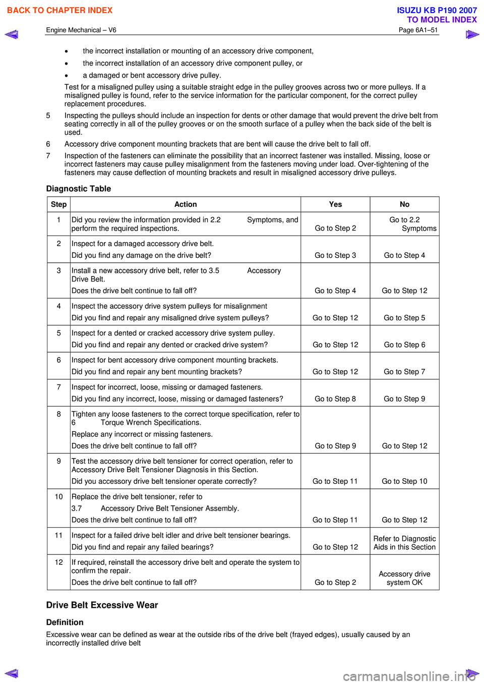
4 Misalignment of the pulleys may be caused by:
BACK TO CHAPTER INDEX
TO MODEL INDEX
ISUZU KB P190 2007
Page 2530 of 6020
Engine Mechanical – V6 Page 6A1–51
• the incorrect installation or mounting of an accessory drive component,
• the incorrect installation of an accessory drive component pulley, or
• a damaged or bent accessory drive pulley.
Test for a misaligned pulley using a suitable straight edge in the pulley grooves across two or more pulleys. If a misaligned pulley is found, refer to the service information for the particular component, for the correct pulley
replacement procedures.
5 Inspecting the pulleys should include an inspection for dents or other damage that would prevent the drive belt from seating correctly in all of the pulley grooves or on the smooth surface of a pulley when the back side of the belt is
used.
6 Accessory drive component mounting brackets that are bent will cause the drive belt to fall off.
7 Inspection of the fasteners can eliminate the possibility that an incorrect fastener was installed. Missing, loose or incorrect fasteners may cause pulley misalignment from the fasteners moving under load. Over-tightening of the
fasteners may cause deflection of mounting brackets and result in misaligned accessory drive pulleys.
Diagnostic Table
Step Action Yes No
1 Did you review the information provided in 2.2 Symptoms, and
perform the required inspections. Go to Step 2 Go to 2.2
Symptoms
2 Inspect for a damaged accessory drive belt.
Did you find any damage on the drive belt? Go to Step 3 Go to Step 4
3 Install a new accessory drive belt, refer to 3.5 Accessory Drive Belt.
Does the drive belt continue to fall off? Go to Step 4 Go to Step 12
4 Inspect the accessory drive system pulleys for misalignment
Did you find and repair any misaligned drive system pulleys? Go to Step 12 Go to Step 5
5 Inspect for a dented or cracked accessory drive system pulley. Did you find and repair any dented or cracked drive system? Go to Step 12 Go to Step 6
6 Inspect for bent accessory drive component mounting brackets.
Did you find and repair any bent mounting brackets? Go to Step 12 Go to Step 7
7 Inspect for incorrect, loose, missing or damaged fasteners. Did you find any incorrect, loose, missing or damaged fasteners? Go to Step 8 Go to Step 9
8 Tighten any loose fasteners to the correct torque specification, refer to 6 Torque W rench Specifications.
Replace any incorrect or missing fasteners.
Does the drive belt continue to fall off? Go to Step 9 Go to Step 12
9 Test the accessory drive belt tensioner for correct operation, refer to
Accessory Drive Belt Tensioner Diagnosis in this Section.
Did you accessory drive belt tensioner operate correctly? Go to Step 11 Go to Step 10
10 Replace the drive belt tensioner, refer to
3.7 Accessory Drive Belt Tensioner Assembly.
Does the drive belt continue to fall off? Go to Step 11 Go to Step 12
11 Inspect for a failed drive belt idler and drive belt tensioner bearings.
Did you find and repair any failed bearings? Go to Step 12 Refer to Diagnostic
Aids in this Section
12 If required, reinstall the accessory drive belt and operate the system to confirm the repair.
Does the drive belt continue to fall off? Go to Step 2 Accessory drive
system OK
Drive Belt Excessive Wear
Definition
Excessive wear can be defined as wear at the outside ribs of the drive belt (frayed edges), usually caused by an
incorrectly installed drive belt
BACK TO CHAPTER INDEX
TO MODEL INDEX
ISUZU KB P190 2007
Page 2534 of 6020
Engine Mechanical – V6 Page 6A1–55
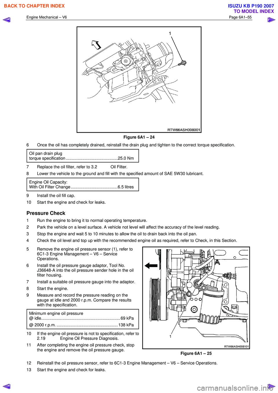
Figure 6A1 – 24
6 Once the oil has completely drained, reinstall the drain plug and tighten to the correct torque specification.
Oil pan drain plug
torque specification ............................................25.0 Nm
7 Replace the oil filter, refer to 3.2 Oil Filter.
8 Lower the vehicle to the ground and fill with the specified amount of SAE 5W 30 lubricant.
Engine Oil Capacity:
With Oil Filter Change ........................................6.5 litres
9 Install the oil fill cap.
10 Start the engine and check for leaks.
Pressure Check
1 Run the engine to bring it to normal operating temperature.
2 Park the vehicle on a level surface. A vehicle not level will affect the accuracy of the level reading.
3 Stop the engine and wait 5 to 10 minutes to allow the oil to drain back into the oil pan.
4 Check the oil level and top up with the recommended engine oil as required, refer to Check, in this Section.
5 Remove the engine oil pressure sensor (1), refer to 6C1-3 Engine Management – V6 – Service
Operations.
6 Install the oil pressure gauge adaptor, Tool No. J36648-A into the oil pressure sender hole in the oil
filter housing.
7 Install a suitable oil pressure gauge into the adaptor.
8 Start the engine.
9 Measure and record the pressure reading on the gauge at idle and 2000 r.p.m. Compare the results
with the specification.
Minimum engine oil pressure
@ idle................................................................... 69 kPa
@ 2000 r.p.m. .................................................... 138 kPa
10 If the engine oil pressure is not to specification, refer to 2.19 Engine Oil Pressure Diagnosis.
11 After completing the engine oil pressure check, stop the engine and remove the oil pressure gauge.
Figure 6A1 – 25
12 Reinstall the oil pressure sensor, refer to 6C1-3 Engine Management – V6 – Service Operations.
13 Start the engine and check for leaks.
BACK TO CHAPTER INDEX
TO MODEL INDEX
ISUZU KB P190 2007
Page 2544 of 6020
Engine Mechanical – V6 Page 6A1–65
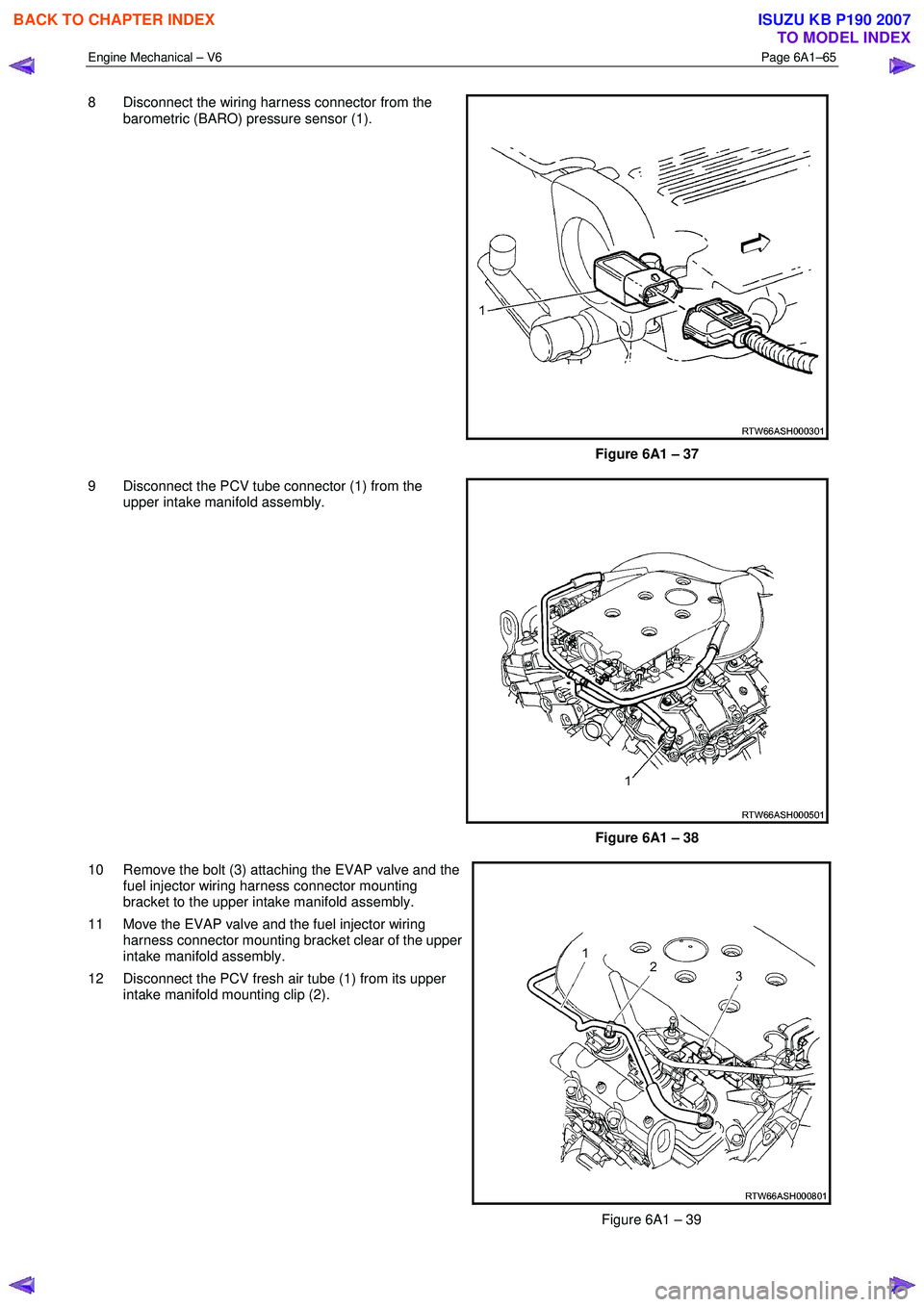
8 Disconnect the wiring harness connector from the
barometric (BARO) pressure sensor (1).
Figure 6A1 – 37
9 Disconnect the PCV tube connector (1) from the upper intake manifold assembly.
Figure 6A1 – 38
10 Remove the bolt (3) attaching the EVAP valve and the fuel injector wiring harness connector mounting
bracket to the upper intake manifold assembly.
11 Move the EVAP valve and the fuel injector wiring harness connector mounting bracket clear of the upper
intake manifold assembly.
12 Disconnect the PCV fresh air tube (1) from its upper intake manifold mounting clip (2).
Figure 6A1 – 39
BACK TO CHAPTER INDEX
TO MODEL INDEX
ISUZU KB P190 2007