2007 ISUZU KB P190 engine mount
[x] Cancel search: engine mountPage 2224 of 6020
6E–54 ENGINE DRIVEABILITY AND EMISSIONS
GENERAL DESCRIPTION FOR ELECTRIC
IGNITION SYSTEM
The engine use two ignition coils, one per two cylinders.
A two wire connector provides a battery voltage primary
supply through the ignition fuse.
The ignition control spark timing is the ECM’s method of
controlling the spark advance and the ignition dwell.
The ignition control spark advance and the ignition dwell
are calculated by the ECM using the following inputs.
• Engine speed
• Crankshaft position (CKP) sensor
• Engine coolant temperature (ECT) sensor
• Throttle position sensor
• Vehicle speed sensor
• ECM and ignition system supply voltage
Ignition coil works to generate only the secondary
voltage be receiving the primary voltage from ECM.
The primary voltage is generated at the coil driver
located in the ECM. The coil driver generate the primary
voltage based on the crankshaft position signal. In
accordance with the crankshaft position signal, ignition
coil driver determines the adequate ignition timing and
also cylinder number to ignite.
Ignition timing is determined the coolant temperature,
intake air temperature, engine speed, engine load,
knock sensor signal, etc.
Spark Plug
Although worn or dirty spark plugs may give satisfactory
operation at idling speed, they frequently fail at higher
engine speeds. Faulty spark plugs may cause poor fuel
economy, power loss, loss of speed, hard starting and
generally poor engine performance. Follow the
scheduled maintenance service recommendations to
ensure satisfactory spark plug performance. Refer to
Maintenance and Lubrication .
Normal spark plug operation will result in brown to
grayish-tan deposits appearing on the insulator portion
of the spark plug. A small amount of red-brown, yellow,
and white powdery material may also be present on the
insulator tip around the center electrode. These
deposits are normal combustion by-products of fuels
and lubricating oils with additives. Some electrode wear
will also occur. Engines which are not running properly
are often referred to as “misfiring.” This means the
ignition spark is not igniting the air/fuel mixture at the
proper time. While other ignition and fuel system causes
must also be considered, possible causes include
ignition system conditions which allow the spark voltage
to reach ground in some other manner than by jumping
across the air gap at the tip of the spark plug, leaving
the air/fuel mixture unburned. Misfiring may also occur
when the tip of the spark plug becomes overheated and
ignites the mixture before the spark jumps. This is
referred to as “pre-ignition.”
Spark plugs may also misfire due to fouling, excessive
gap, or a cracked or broken insulator. If misfiring occurs before the recommended replacement interval, locate
and correct the cause.
Carbon fouling of the spark plug is indicated by dry,
black carbon (soot) deposits on the portion of the spark
plug in the cylinder. Excessive idling and slow speeds
under light engine loads can keep the spark plug
temperatures so low that these deposits are not burned
off. Very rich fuel mixtures or poor ignition system output
may also be the cause. Refer to DTC P1167.
Oil fouling of the spark plug is indicated by wet oily
deposits on the portion of the spark plug in the cylinder,
usually with little electrode wear. This may be caused by
oil during break-in of new or newly overhauled engines.
Deposit fouling of the spark plug occurs when the
normal red-brown, yellow or white deposits of
combustion by-products become sufficient to cause
misfiring. In some cases, these deposits may melt and
form a shiny glaze on the insulator around the center
electrode. If the fouling is found in only one or two
cylinders, valve stem clearances or intake valve seals
may be allowing excess lubricating oil to enter the
cylinder, particularly if the deposits are heavier on the
side of the spark plug facing the intake valve.
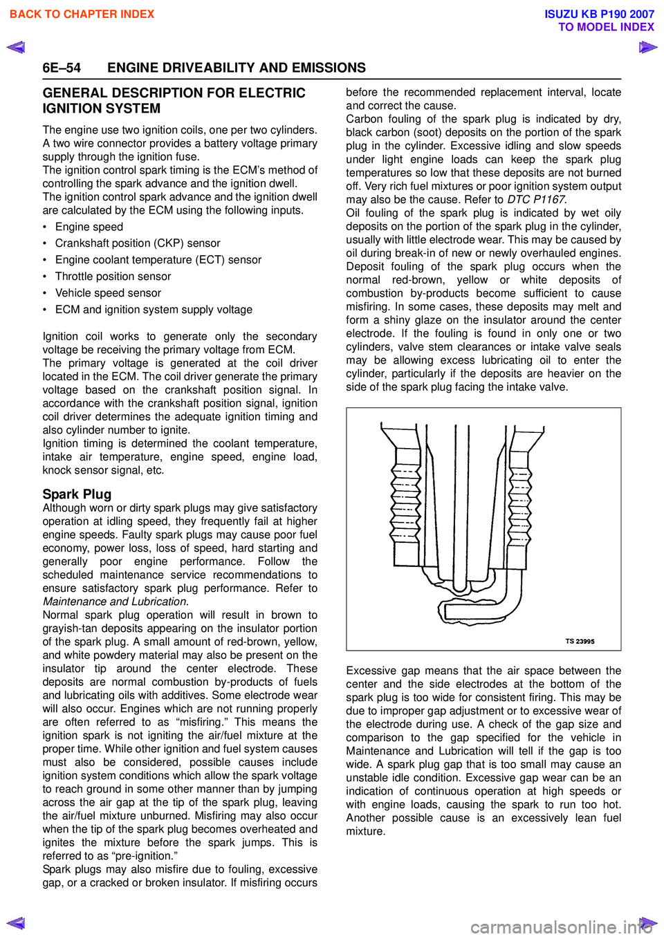
Excessive gap means that the air space between the
center and the side electrodes at the bottom of the
spark plug is too wide for consistent firing. This may be
due to improper gap adjustment or to excessive wear of
the electrode during use. A check of the gap size and
comparison to the gap specified for the vehicle in
Maintenance and Lubrication will tell if the gap is too
wide. A spark plug gap that is too small may cause an
unstable idle condition. Excessive gap wear can be an
indication of continuous operation at high speeds or
with engine loads, causing the spark to run too hot.
Another possible cause is an excessively lean fuel
mixture.
BACK TO CHAPTER INDEX
TO MODEL INDEX
ISUZU KB P190 2007
Page 2225 of 6020
ENGINE DRIVEABILITY AND EMISSIONS 6E–55
Low or high spark plug installation torque or improper
seating can result in the spark plug running too hot and
can cause excessive center electrode wear. The plug
and the cylinder head seats must be in good contact for
proper heat transfer and spark plug cooling. Dirty or
damaged threads in the head or on the spark plug can
keep it from seating even though the proper torque is
applied. Once spark plugs are properly seated, tighten
them to the torque shown in the Specifications Table.
Low torque may result in poor contact of the seats due
to a loose spark plug. Over tightening may cause the
spark plug shell to be stretched and will result in poor
contact between the seats. In extreme cases, exhaust
blow-by and damage beyond simple gap wear may
occur.
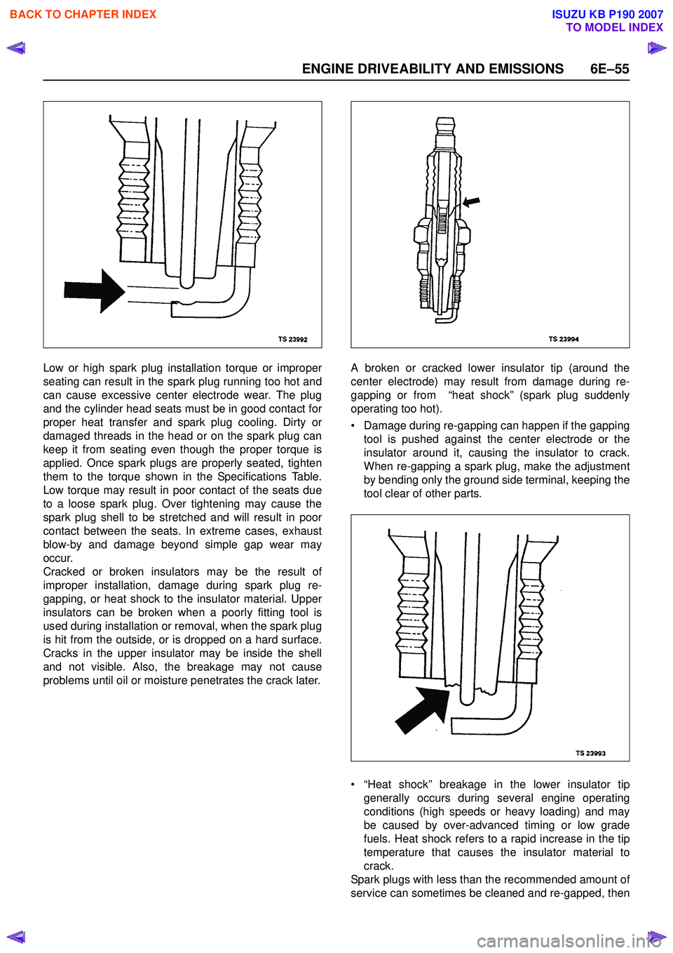
Cracked or broken insulators may be the result of
improper installation, damage during spark plug re-
gapping, or heat shock to the insulator material. Upper
insulators can be broken when a poorly fitting tool is
used during installation or removal, when the spark plug
is hit from the outside, or is dropped on a hard surface.
Cracks in the upper insulator may be inside the shell
and not visible. Also, the breakage may not cause
problems until oil or moisture penetrates the crack later. A broken or cracked lower insulator tip (around the
center electrode) may result from damage during re-
gapping or from “heat shock” (spark plug suddenly
operating too hot).
• Damage during re-gapping can happen if the gapping tool is pushed against the center electrode or the
insulator around it, causing the insulator to crack.
When re-gapping a spark plug, make the adjustment
by bending only the ground side terminal, keeping the
tool clear of other parts.
• “Heat shock” breakage in the lower insulator tip generally occurs during several engine operating
conditions (high speeds or heavy loading) and may
be caused by over-advanced timing or low grade
fuels. Heat shock refers to a rapid increase in the tip
temperature that causes the insulator material to
crack.
Spark plugs with less than the recommended amount of
service can sometimes be cleaned and re-gapped, then
BACK TO CHAPTER INDEX
TO MODEL INDEX
ISUZU KB P190 2007
Page 2227 of 6020
ENGINE DRIVEABILITY AND EMISSIONS 6E–57
GENERAL DESCRIPTION FOR
EVAPORATIVE EMISSION SYSTEM
EVAP Emission Control System Purpose
The basic evaporative emission control system used on
the charcoal canister storage method. The method
transfers fuel vapor from the fuel tank to an activated
carbon (charcoal) storage devise to hold the vapors
when the vehicle is not operating.
The canister is located on the rear axle housing by the
frame cross-member.
When the engine is running, the fuel vapor is purged
from the carbon element by intake air flow and
consumed in the normal combustion process.
EVAP Emission Control System Operation
The EVAP canister purge is controlled by a solenoid
valve that allows the manifold vacuum to purge the
canister. The engine control module (ECM) supplies a
ground to energize the solenoid valve (purge on). The
EVAP purge solenoid control is pulse-width modulated
(PWM) (turned on and off several times a second). The
duty cycle (pulse width) is determined by engine
operating conditions including load, throttle position,
coolant temperature and ambient temperature. The duty
cycle is calculated by the ECM. the output is
commanded when the appropriate conditions have
been met. These conditions are:
• The engine is fully warmed up.
• The engine has been running for a specified time.
• The IAT reading is above 10°C (50°F).
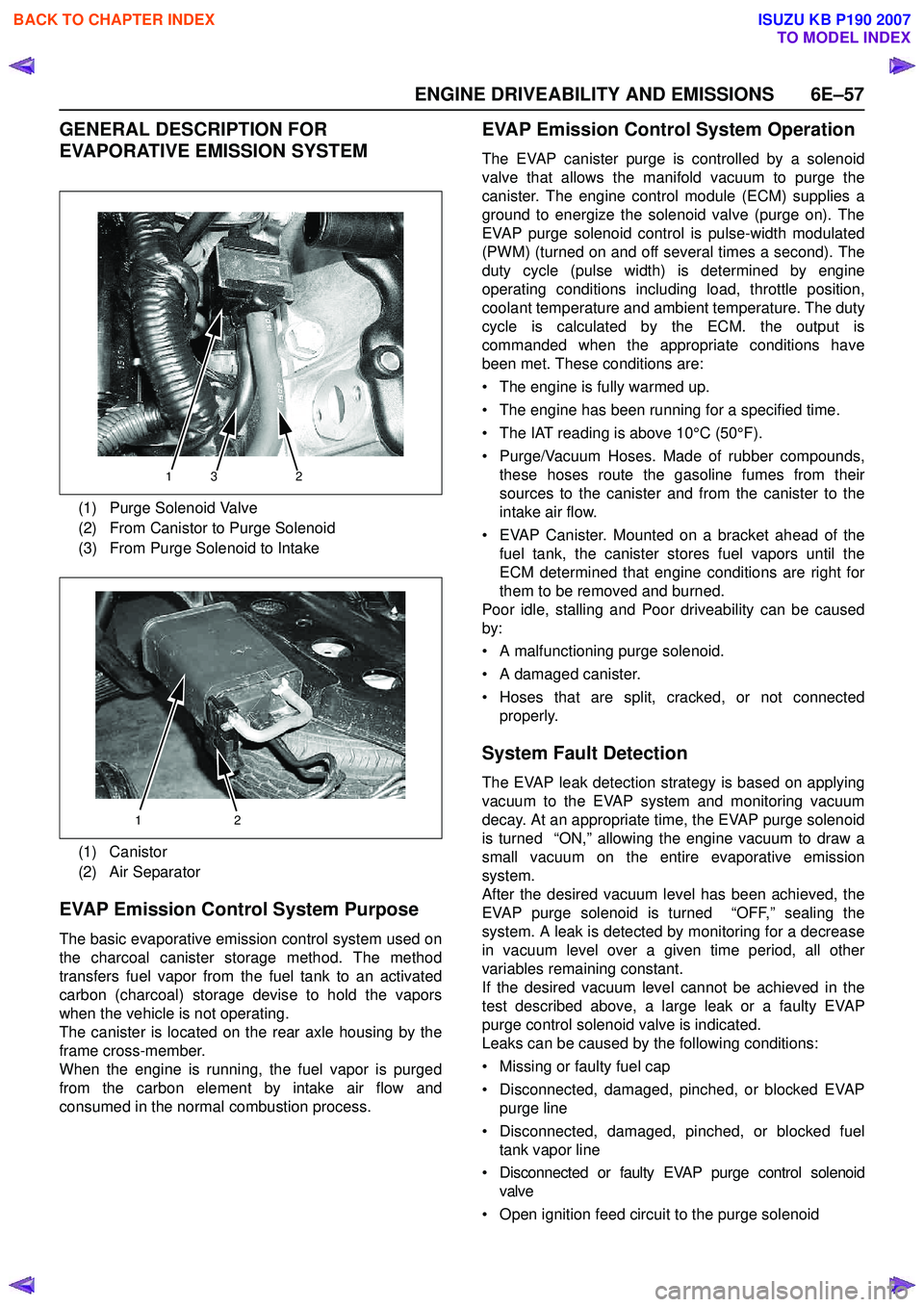
• Purge/Vacuum Hoses. Made of rubber compounds, these hoses route the gasoline fumes from their
sources to the canister and from the canister to the
intake air flow.
• EVAP Canister. Mounted on a bracket ahead of the fuel tank, the canister stores fuel vapors until the
ECM determined that engine conditions are right for
them to be removed and burned.
Poor idle, stalling and Poor driveability can be caused
by:
• A malfunctioning purge solenoid.
• A damaged canister.
• Hoses that are split, cracked, or not connected properly.
System Fault Detection
The EVAP leak detection strategy is based on applying
vacuum to the EVAP system and monitoring vacuum
decay. At an appropriate time, the EVAP purge solenoid
is turned “ON,” allowing the engine vacuum to draw a
small vacuum on the entire evaporative emission
system.
After the desired vacuum level has been achieved, the
EVAP purge solenoid is turned “OFF,” sealing the
system. A leak is detected by monitoring for a decrease
in vacuum level over a given time period, all other
variables remaining constant.
If the desired vacuum level cannot be achieved in the
test described above, a large leak or a faulty EVAP
purge control solenoid valve is indicated.
Leaks can be caused by the following conditions:
• Missing or faulty fuel cap
• Disconnected, damaged, pinched, or blocked EVAP purge line
• Disconnected, damaged, pinched, or blocked fuel tank vapor line
• Disconnected or faulty EVAP purge control solenoid valve
• Open ignition feed circuit to the purge solenoid
(1) Purge Solenoid Valve
(2) From Canistor to Purge Solenoid
(3) From Purge Solenoid to Intake
(1) Canistor
(2) Air Separator
132
12
BACK TO CHAPTER INDEX
TO MODEL INDEX
ISUZU KB P190 2007
Page 2229 of 6020
ENGINE DRIVEABILITY AND EMISSIONS 6E–59
POSITIVE CRANKCASE VENTILATION
(PCV) SYSTEM
Crankcase Ventilation System Purpose
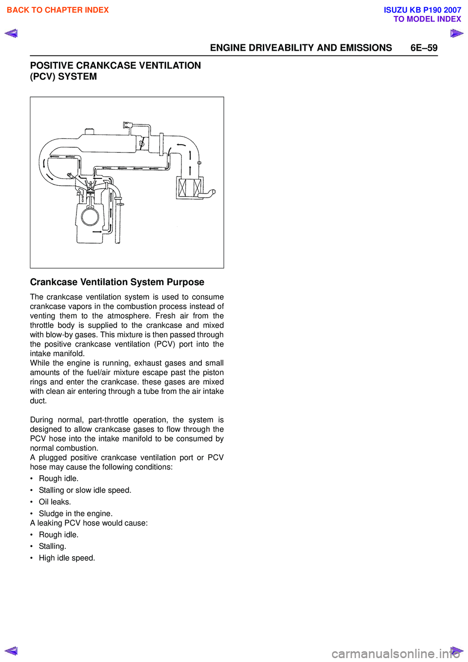
The crankcase ventilation system is used to consume
crankcase vapors in the combustion process instead of
venting them to the atmosphere. Fresh air from the
throttle body is supplied to the crankcase and mixed
with blow-by gases. This mixture is then passed through
the positive crankcase ventilation (PCV) port into the
intake manifold.
While the engine is running, exhaust gases and small
amounts of the fuel/air mixture escape past the piston
rings and enter the crankcase. these gases are mixed
with clean air entering through a tube from the air intake
duct.
During normal, part-throttle operation, the system is
designed to allow crankcase gases to flow through the
PCV hose into the intake manifold to be consumed by
normal combustion.
A plugged positive crankcase ventilation port or PCV
hose may cause the following conditions:
• Rough idle.
• Stalling or slow idle speed.
• Oil leaks.
• Sludge in the engine.
A leaking PCV hose would cause:
• Rough idle.
• Stalling.
• High idle speed.
BACK TO CHAPTER INDEX
TO MODEL INDEX
ISUZU KB P190 2007
Page 2234 of 6020
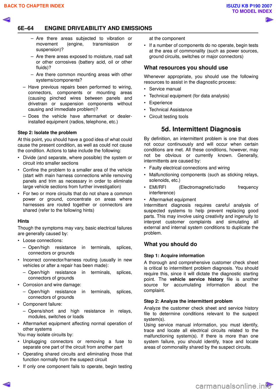
6E–64 ENGINE DRIVEABILITY AND EMISSIONS
– Are there areas subjected to vibration ormovement (engine, transmission or
suspension)?
– Are there areas exposed to moisture, road salt or other corrosives (battery acid, oil or other
fluids)?
– Are there common mounting areas with other systems/components?
– Have previous repairs been performed to wiring, connectors, components or mounting areas
(causing pinched wires between panels and
drivetrain or suspension components without
causing and immediate problem)?
– Does the vehicle have aftermarket or dealer- installed equipment (radios, telephone, etc.)
Step 2: Isolate the problem
At this point, you should have a good idea of what could
cause the present condition, as well as could not cause
the condition. Actions to take include the following:
• Divide (and separate, where possible) the system or circuit into smaller sections
• Confine the problem to a smaller area of the vehicle (start with main harness connections while removing
panels and trim as necessary in order to eliminate
large vehicle sections from further investigation)
• For two or more circuits that do not share a common power or ground, concentrate on areas where
harnesses are routed together or connectors are
shared (refer to the following hints)
Hints
Though the symptoms may vary, basic electrical failures
are generally caused by:
• Loose connections: – Open/high resistance in terminals, splices,connectors or grounds
• Incorrect connector/harness routing (usually in new vehicles or after a repair has been made):
– Open/high resistance in terminals, splices, connectors of grounds
• Corrosion and wire damage:
– Open/high resistance in terminals, splices,connectors of grounds
• Component failure: – Opens/short and high resistance in relays,modules, switches or loads
• Aftermarket equipment affecting normal operation of other systems
You may isolate circuits by:
• Unplugging connectors or removing a fuse to separate one part of the circuit from another part
• Operating shared circuits and eliminating those that function normally from the suspect circuit
• If only one component fails to operate, begin testing at the component
• If a number of components do no operate, begin tests at the area of commonality (such as power sources,
ground circuits, switches or major connectors)
What resources you should use
Whenever appropriate, you should use the following
resources to assist in the diagnostic process:
• Service manual
• Technical equipment (for data analysis)
• Experience
• Technical Assistance
• Circuit testing tools
5d. Intermittent Diagnosis
By definition, an intermittent problem is one that does
not occur continuously and will occur when certain
conditions are met. All these conditions, however, may
not be obvious or currently known. Generally,
intermittents are caused by:
• Faulty electrical connections and wiring
• Malfunctioning components (such as sticking relays, solenoids, etc.)
• EMI/RFI (Electromagnetic/radio frequency interference)
• Aftermarket equipment
Intermittent diagnosis requires careful analysis of
suspected systems to help prevent replacing good
parts. This may involve using creativity and ingenuity to
interpret customer complaints and simulating all
external and internal system conditions to duplicate the
problem.
What you should do
Step 1: Acquire information
A thorough and comprehensive customer check sheet
is critical to intermittent problem diagnosis. You should
require this, since it will dictate the diagnostic starting
point. The vehicle service history file is another
source for accumulating information about the
complaint.
Step 2: Analyze the intermittent problem
Analyze the customer check sheet and service history
file to determine conditions relevant to the suspect
system(s).
Using service manual information, you must identify,
trace and locate all electrical circuits related to the
malfunctioning system(s). If there is more than one
system failure, you should identify, trace and locate
areas of commonality shared by the suspect circuits.
BACK TO CHAPTER INDEX
TO MODEL INDEX
ISUZU KB P190 2007
Page 2242 of 6020
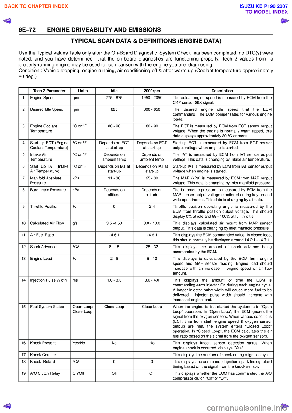
6E–72 ENGINE DRIVEABILITY AND EMISSIONS
TYPICAL SCAN DATA & DEFINITIONS (ENGINE DATA)
Use the Typical Values Table only after the On-Board Diagnostic System Check has been completed, no DTC(s) were
noted, and you have determined that the on-board diagnostics are functioning properly. Tech 2 values from a
properly-running engine may be used for comparison with the engine you are diagnosing.
Condition : Vehicle stopping, engine running, air conditioning off & after warm-up (Coolant temperature approximately
80 deg.)
Tech 2 ParameterUnitsIdle2000rpmDescription
1 Engine Speed rpm775 - 8751950 - 2050 The actual engine speed is measured by ECM from the
CKP sensor 58X signal.
2 Desired Idle Speed rpm825800 - 850 The desired engine idle speed that the ECMcommanding. The ECM compensates for various engine
loads.
3 Engine Coolant Temperature °C or °F80 - 9080 - 90 The ECT is measured by ECM from ECT sensor output
voltage. When the engine is normally warm upped, this
data displays approximately 80 °C or more.
4 Start Up ECT (Engine Coolant Temperature) °C or °FDepends on ECT
at start-upDepends on ECT at start-up Start-up ECT is measured by ECM from ECT sensor
output voltage when engine is started.
5Intake Air
Temperature °C or °FDepends on
ambient tempDepends on
ambient temp The IAT is measured by ECM from IAT sensor output
voltage. This data is changing by intake air temperature.
6 Start Up IAT (Intake Air Temperature) °C or °FDepends on IAT at
start-upDepends on IAT at start-up Start-up IAT is measured by ECM from IAT sensor output
voltage when engine is started.
7 Manifold Absolute Pressure kPa31 - 3625 - 30The MAP (kPa) is measured by ECM from MAP output
voltage. This data is changing by inlet manifold pressure.
8 Barometric Pressure kPaDepends on altitudeDepends on altitude The barometric pressure is measured by ECM from the
MAP sensor output voltage monitored during key up and
wide open throttle. This data is changing by altitude.
9 Throttle Position %02-4 Throttle position operating angle is measured by the ECM from throttle position output voltage. This should
display 0% at idle and 99 - 100% at full throttle.
10 Calculated Air Flow g/s3.5 -4.508.0 - 10.0 This displays calculated air mount from MAP sensor output. This data is changing by inlet manifold pressure.
11 Air Fuel Ratio14.6:114.6:1 This displays the ECM commanded value. In closed loop,this should normally be displayed around 14.2:1 - 14.7:1.
12 Spark Advance °CA8 - 1525 - 32 This displays the amount of spark advance being commanded by the ECM.
13 Engine Load %2 - 55 - 10 This displays is calculated by the ECM form engine
speed and MAF sensor reading. Engine load should
increase with an increase in engine speed or air flow
amount.
14 Injection Pulse Width ms1.0 - 3.0 3.0 - 4.0 This displays the amount of time the ECM is commanding each injector On during each engine cycle.
A longer injector pulse width will cause more fuel to be
delivered. Injector pulse width should increase with
increased engine load.
15 Fuel System Status Open Loop/ Close LoopClose LoopClose Loop When the engine is first started the system is in “OpenLoop” operation. In “Open Loop”, the ECM ignores the
signal from the oxygen sensors. When various conditions
(ECT, time from start, engine speed & oxygen sensor
output) are met, the system enters “Closed Loop”
operation. In “Closed Loop”, the ECM calculates the air
fuel ratio based on the signal from the oxygen sensors.
16 Knock Present Yes/NoNoNo This displays knock sensor detection status. When engine knock is occurred, displays "Yes".
17 Knock Counter--This displays the number of knock during a ignition cycle.
18 Knock Retard °CA00 This displays the commanded ignition spark timing retard
timing based on the signal from the knock sensor.
19 A/C Clutch Relay On/OffOffOff This displays whether the ECM has commanded the A/C compressor clutch “On” or “Off”.
BACK TO CHAPTER INDEX
TO MODEL INDEX
ISUZU KB P190 2007
Page 2244 of 6020

6E–74 ENGINE DRIVEABILITY AND EMISSIONS
TYPICAL SCAN DATA & DEFINITIONS (O2 SENSOR DATA)
Use the Typical Values Table only after the On-Board Diagnostic System Check has been completed, no DTC(s) were
noted, and you have determined that the on-board diagnostics are functioning properly. Tech 2 values from a
properly-running engine may be used for comparison with the engine you are diagnosing.
Condition : Vehicle stopping, engine running, air conditioning off & after warm-up (Coolant temperature approximately
80 deg.)
Tech 2 ParameterUnitsIdle2000rpmDescription
1 Engine Speed rpm710 - 8751950 - 2050 The actual engine speed is measured by ECM from the
CKP sensor 58X signal.
2 Desired Idle Speed rpm825800 - 850 The desired engine idle speed that the ECMcommanding. The ECM compensates for various engine
loads.
3 Engine Coolant Temperature °C or °F80 - 9080 - 90 The ECT is measured by ECM from ECT sensor output
voltage. When the engine is normally warm upped, this
data displays approximately 80 °C or more.
4 Start Up ECT (Engine Coolant Temperature) °C or °FDepends on ECT
at start-upDepends on ECT at start-up Start-up ECT is measured by ECM from ECT sensor
output voltage when engine is started.
5Intake Air
Temperature °C or °FDepends on
ambient tempDepends on
ambient temp The IAT is measured by ECM from IAT sensor output
voltage. This data is changing by intake air temperature.
6 Start Up IAT (Intake Air Temperature) °C or °FDepends on IAT at
start-upDepends on IAT at start-up Start-up IAT is measured by ECM from IAT sensor output
voltage when engine is started.
7 Manifold Absolute Pressure kPa31 - 3625 - 30The MAP (kPa) is measured by ECM from MAP output
voltage. This data is changing by inlet manifold pressure.
8 Barometric Pressure kPaDepends on altitudeDepends on altitude The barometric pressure is measured by ECM from the
MAP sensor output voltage monitored during key up and
wide open throttle. This data is changing by altitude.
9 Throttle Position %02 - 4 Throttle position operating angle is measured by the ECM from throttle position output voltage. This should
display 0% at idle and 99 - 100% at full throttle.
10 Calculated Air Flow g/s3.5 -4.508.0 - 10.0 This displays intake air amount. The mass air flow is measured by ECM from the MAF sensor output voltage.
11 Air Fuel Ratio14.6:114.6:1 This displays the ECM commanded value. In closedloop, this should normally be displayed around 14.2:1 -
14.7:1.
12 Fuel System Status Open Loop/ Close LoopClose LoopClose Loop When the engine is first started the system is in “OpenLoop” operation. In “Open Loop”, the ECM ignores the
signal from the oxygen sensors. When various
conditions (ECT, time from start, engine speed & oxygen
sensor output) are met, the system enters “Closed Loop”
operation. In “Closed Loop”, the ECM calculates the air
fuel ratio based on the signal from the oxygen sensors.
13 Engine Load %2 - 55 - 10 This displays is calculated by the ECM form engine
speed and MAF sensor reading. Engine load should
increase with an increase in engine speed or air flow
amount.
14B1 O2 Sensor Ready
(Bank 1)Ye s / N oYe sYes This displays the status of the exhaust oxygen sensor. This display will indicate “Yes” when the ECM detects a
fluctuating oxygen sensor output voltage sufficient to
allow closed loop operation. This will not occur unless
the oxygen sensor is warmed up.
15B1S1 Status
(Bank 1 Sensor 1)Rich / LeanRich / LeanRich / Lean This displays dependent on the exhaust oxygen sensor output voltage. Should fluctuate constantly “Rich” and
“Lean” in closed loop.
16 Fuel Trim Learned Yes/NoYe sYes When conditions are appropriate for enabling long term fuel trim corrections, fuel trim learn will display “Yes”.
This indicates that the long term fuel trim is responding
to the short term fuel trim. If the fuel trim lean displays
“No”, then long term fuel trim will not respond to changes
in short term fuel trim.
BACK TO CHAPTER INDEX
TO MODEL INDEX
ISUZU KB P190 2007
Page 2245 of 6020
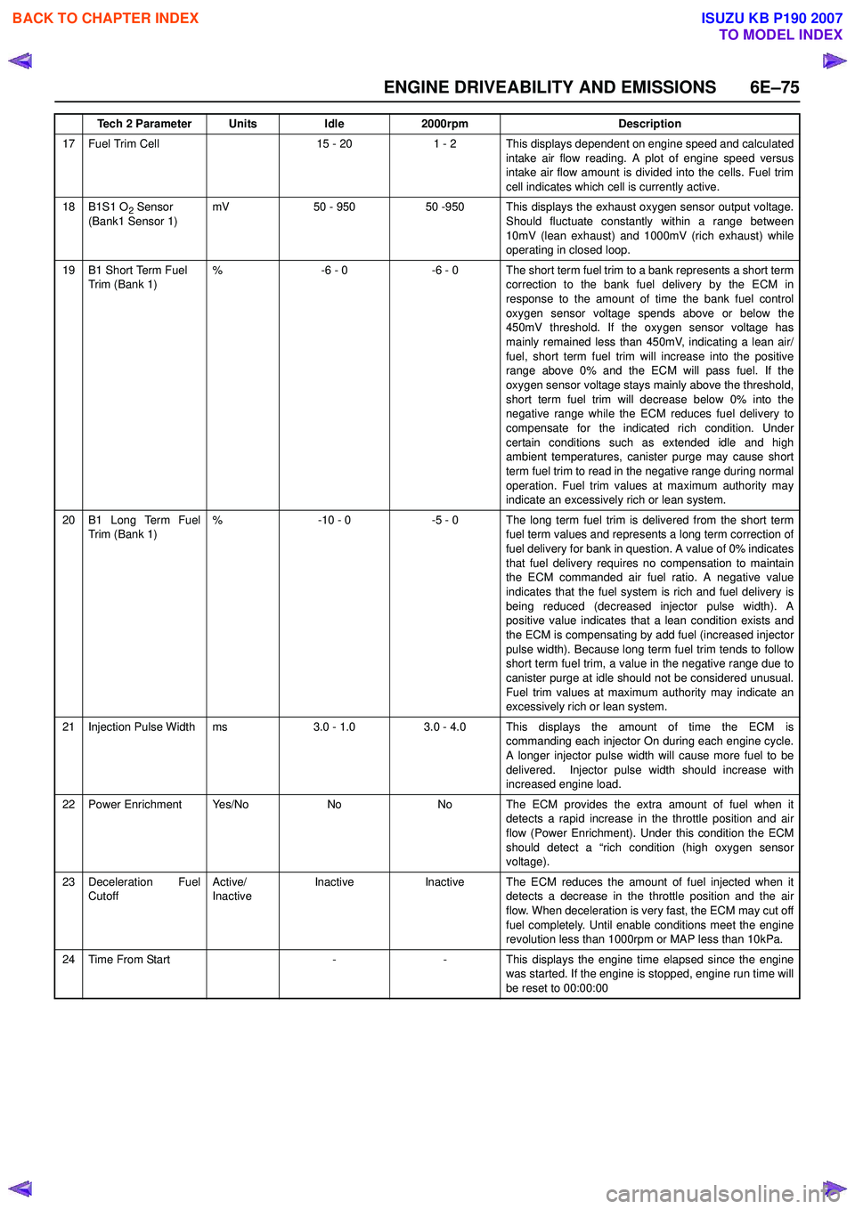
ENGINE DRIVEABILITY AND EMISSIONS 6E–75
17 Fuel Trim Cell15 - 201 - 2 This displays dependent on engine speed and calculatedintake air flow reading. A plot of engine speed versus
intake air flow amount is divided into the cells. Fuel trim
cell indicates which cell is currently active.
18B1S1 O2 Sensor
(Bank1 Sensor 1)mV50 - 95050 -950 This displays the exhaust oxygen sensor output voltage. Should fluctuate constantly within a range between
10mV (lean exhaust) and 1000mV (rich exhaust) while
operating in closed loop.
19B1 Short Term Fuel
Trim (Bank 1)%-6 - 0-6 - 0 The short term fuel trim to a bank represents a short term correction to the bank fuel delivery by the ECM in
response to the amount of time the bank fuel control
oxygen sensor voltage spends above or below the
450mV threshold. If the oxygen sensor voltage has
mainly remained less than 450mV, indicating a lean air/
fuel, short term fuel trim will increase into the positive
range above 0% and the ECM will pass fuel. If the
oxygen sensor voltage stays mainly above the threshold,
short term fuel trim will decrease below 0% into the
negative range while the ECM reduces fuel delivery to
compensate for the indicated rich condition. Under
certain conditions such as extended idle and high
ambient temperatures, canister purge may cause short
term fuel trim to read in the negative range during normal
operation. Fuel trim values at maximum authority may
indicate an excessively rich or lean system.
20B1 Long Term Fuel
Trim (Bank 1)%-10 - 0-5 - 0 The long term fuel trim is delivered from the short term fuel term values and represents a long term correction of
fuel delivery for bank in question. A value of 0% indicates
that fuel delivery requires no compensation to maintain
the ECM commanded air fuel ratio. A negative value
indicates that the fuel system is rich and fuel delivery is
being reduced (decreased injector pulse width). A
positive value indicates that a lean condition exists and
the ECM is compensating by add fuel (increased injector
pulse width). Because long term fuel trim tends to follow
short term fuel trim, a value in the negative range due to
canister purge at idle should not be considered unusual.
Fuel trim values at maximum authority may indicate an
excessively rich or lean system.
21Injection Pulse Widthms3.0 - 1.03.0 - 4.0 This displays the amount of time the ECM is commanding each injector On during each engine cycle.
A longer injector pulse width will cause more fuel to be
delivered. Injector pulse width should increase with
increased engine load.
22Power EnrichmentYe s / N oNoNo The ECM provides the extra amount of fuel when it detects a rapid increase in the throttle position and air
flow (Power Enrichment). Under this condition the ECM
should detect a “rich condition (high oxygen sensor
voltage).
23Deceleration Fuel
Cutoff Active/
InactiveInactiveInactiveThe ECM reduces the amount of fuel injected when it
detects a decrease in the throttle position and the air
flow. When deceleration is very fast, the ECM may cut off
fuel completely. Until enable conditions meet the engine
revolution less than 1000rpm or MAP less than 10kPa.
24Time From Start--This displays the engine time elapsed since the engine
was started. If the engine is stopped, engine run time will
be reset to 00:00:00
Tech 2 ParameterUnitsIdle2000rpmDescription
BACK TO CHAPTER INDEX
TO MODEL INDEX
ISUZU KB P190 2007