Page 2027 of 6020

ENGINE MECHANICAL (C24SE) 6A-13
Valve System C24SE
Actuation Type Direct-acting Inverted Bucked Tappet
Valve Clearance Adjustment Hydraulic
Valve Rotor Type None
Inlet-Valve Material Chromium Alloyed Steel
-Seat Insert MaterialSintered Iron
Exhaust-Valve Material Head: Cr-Mn-Ni Alloyed Shaft: Cr-Si Alloyed &Cr plated
-Seat Insert MaterialSintered Iron
Valve Spring Material GME 06 100-C1
Valve Guide Material QS 13 MR 00
Valve Seal Type Lip
Water Pump C24SE
Type Centrifugal
Drive-Material &Type HNBR Toothed-belt
Bearing Type Double Row Ball
Shaft Seal Type Mechanical Ceramic
Thermostat-Coolant C24SE
Type Bypass
Oil Pump & Filter C24SE
Type Gear Pump
Location Front of Engine
Drive Direct Crankshaft Driven
Filter Type Full Flow with Bypass for blocked filter
Oil & Oil Reservoir C24SE
Reservoir-Description & Location 1-piece below Engine
Reservoir Material Aluminum Alloy (pressure cast)
Replacement Oil Fill Volume
-W ith Filter change4.25liters
-W ithout Filter change 4.00liters
Recommended Oil-Run-in 10W /30SG
-Service (above-18°C) 10W /40SG
-Service (below-18°C) 5W /30SG
Oil Classification API&CCMC
Ignition Components C24SE
Spark Plugs Conventional
Type Electronic Spark Control
No. of Coils &Type 2 Solid State
Coil Location Engine-mounted
Ignition Lead Type Inductive (hi-resistance)
BACK TO CHAPTER INDEX
TO MODEL INDEX
ISUZU KB P190 2007
Page 2032 of 6020
6A-18 ENGINE MECHANICAL (C24SE)
OPERATIONS ON ENGINE AGGREGATES
Engine Damping Blocks (Engine Without
Transmission)
Removal
1. Remove bonnet.
2. Remove radiator.
3. Remove air inlet hose.
4. Remove power steering pump drive belt and power steering pump from engine.
5. Remove all cable connections, hoses and lines from
engine.
6. Remove accelerator cable from inlet pipe.
7. Remove exhaust pipe from manifold.
8. Remove lower nine bolts and transmission from engine
block.
9. Remove clutch slave cylinder and allow to hang free.
10. Remove starter from engine block.
11. Remove upper bolts of left and right engine mounting
from damping blocks.
12. Raise engine slightly.
13. Remove lower bolts of left and right damping blocks.
14. Remove damping blocks.
BACK TO CHAPTER INDEX
TO MODEL INDEX
ISUZU KB P190 2007
Page 2069 of 6020
ENGINE MECHANICAL (C24SE) 6A-55
OPERATIONS ON REMOVED ENGINE
Crankshaft
Removal
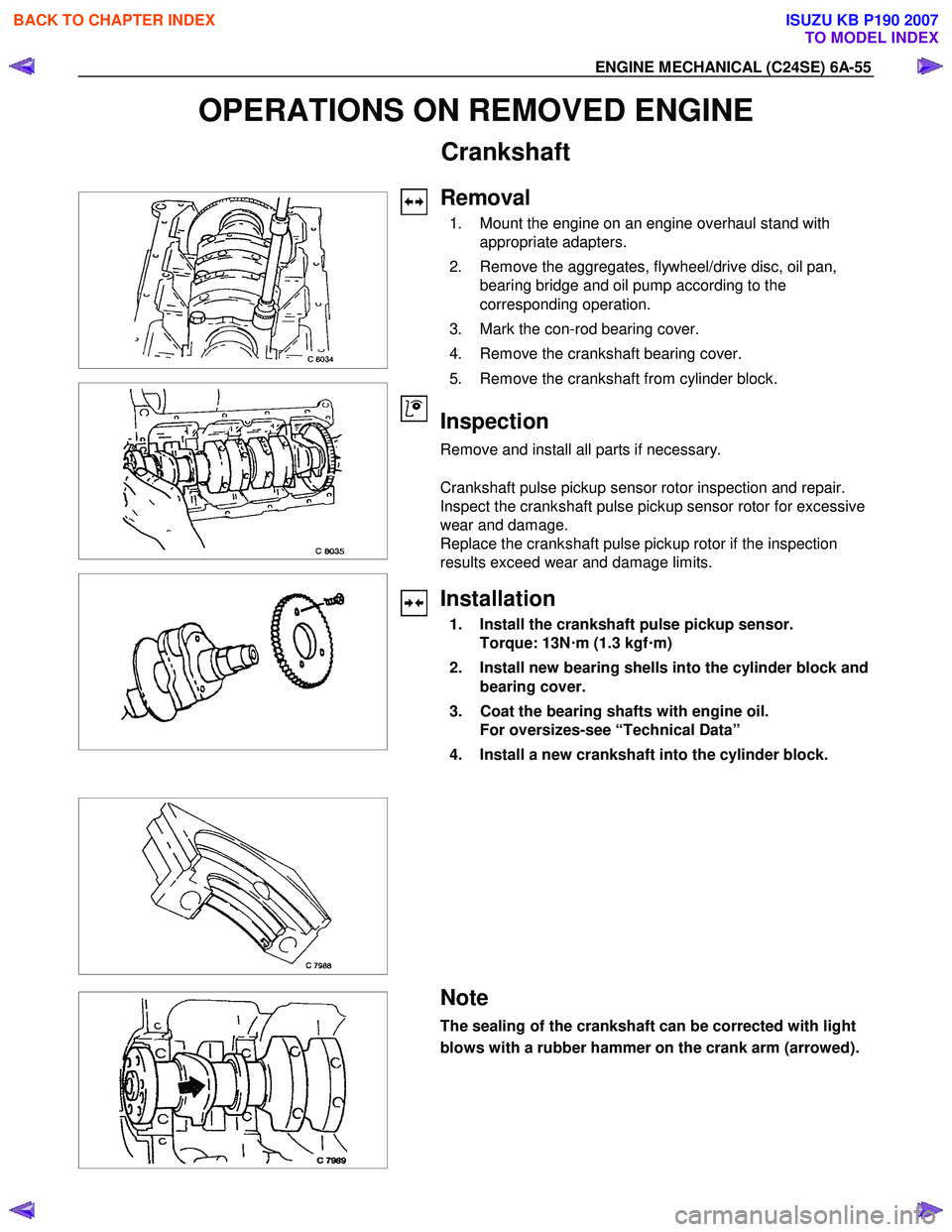
1. Mount the engine on an engine overhaul stand with appropriate adapters.
2. Remove the aggregates, flywheel/drive disc, oil pan, bearing bridge and oil pump according to the
corresponding operation.
3. Mark the con-rod bearing cover.
4. Remove the crankshaft bearing cover.
5. Remove the crankshaft from cylinder block.
Inspection
Remove and install all parts if necessary.
Crankshaft pulse pickup sensor rotor inspection and repair.
Inspect the crankshaft pulse pickup sensor rotor for excessive
wear and damage.
Replace the crankshaft pulse pickup rotor if the inspection
results exceed wear and damage limits.
Installation
1. Install the crankshaft pulse pickup sensor. Torque: 13N !
!!
!
m (1.3 kgf !
!!
!
m)
2. Install new bearing shells into the cylinder block and bearing cover.
3. Coat the bearing shafts with engine oil. For oversizes-see “Technical Data”
4. Install a new crankshaft into the cylinder block.
Note
The sealing of the crankshaft can be corrected with light
blows with a rubber hammer on the crank arm (arrowed).
BACK TO CHAPTER INDEX
TO MODEL INDEX
ISUZU KB P190 2007
Page 2071 of 6020
ENGINE MECHANICAL (C24SE) 6A-57
Inspection
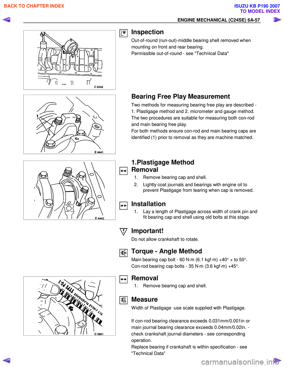
Out-of-round (run-out)-middle bearing shell removed when
mounting on front and rear bearing.
Permissible out-of-round - see "Technical Data"
Bearing Free Play Measurement
Two methods for measuring bearing free play are described -
1. Plastigage method and 2. micrometer and gauge method.
The two procedures are suitable for measuring both con-rod
and main bearing free play.
For both methods ensure con-rod and main bearing caps are
identified (1) prior to removal as they are machine matched.
1.Plastigage Method
Removal
1. Remove bearing cap and shell.
2. Lightly coat journals and bearings with engine oil to prevent Plastigage from tearing when cap is removed.
Installation
1. Lay a length of Plastigage across width of crank pin and fit bearing cap and shell using old bolts at this stage.
Important!
Do not allow crankshaft to rotate.
Torque - Angle Method
Main bearing cap bolt - 60 N ⋅m (6.1 kgf ⋅m) +40 ° + to 50 °.
Con-rod bearing cap bolts - 35 N ⋅m (3.6 kgf ⋅m) +45 °.
Removal
1. Remove bearing cap and shell.
Measure
W idth of Plastigage -use scale supplied with Plastigage.
If con-rod bearing clearance exceeds 0.031mm/0.001in or
main journal bearing clearance exceeds 0.04mm/0.02in. -
check crankshaft journal diameters - see corresponding
operation.
Replace bearing if crankshaft is within specification - see
"Technical Data"
BACK TO CHAPTER INDEX
TO MODEL INDEX
ISUZU KB P190 2007
Page 2084 of 6020
6A-70 ENGINE MECHANICAL (C24SE)
FUEL INJECTION SYSTEM
MAP SENSOR
Removal
1. Disconnect the battery cable.
2. Disconnect the electrical connector from the sensor.
3. Remove the mounting bolts securing the sensor to the manifold.
4. Remove the sensor from the intake manifold.
Installation
1. Push MAP sensor into the manifold.
2. Install the mounting bolts and tighten them.
3. Connect electrical connector.
4. Connect the battery cable.
Pressure Regulator
Removal
1. Remove vacuum hose.
2. Remove fuel hoses.
3. Remove pressure regulator.
Installation
1. Install pressure regulator.
2. Install fuel hoses.
3. Install vacuum hoses.
ECM (Engine Control Module)
Removal
(2.4L)
1. Disconnect the ECM connector.
2. Remove the four hex bolts and nuts.
3. Remove the ECM from the ECM bracket on engine.
BACK TO CHAPTER INDEX
TO MODEL INDEX
ISUZU KB P190 2007
Page 2087 of 6020
ENGINE MECHANICAL (C24SE) 6A-73
FUEL INJECTOR
Removal
Caution: To reduce the risk of fire and personal injury, it is
necessary to relieve the fuel system pressure before
servicing the fuel system components.
Caution: After relieving the fuel system pressure, a small
amount of fuel may be released when servicing fuel lines
or connections. Reduce the chance of personal injury by
covering the fuel line fitting with a shop towel before
disconnecting the fittings. The towel will absorb any fuel
that may leak out. When the disconnect is completed,
place the towel in an approved container.
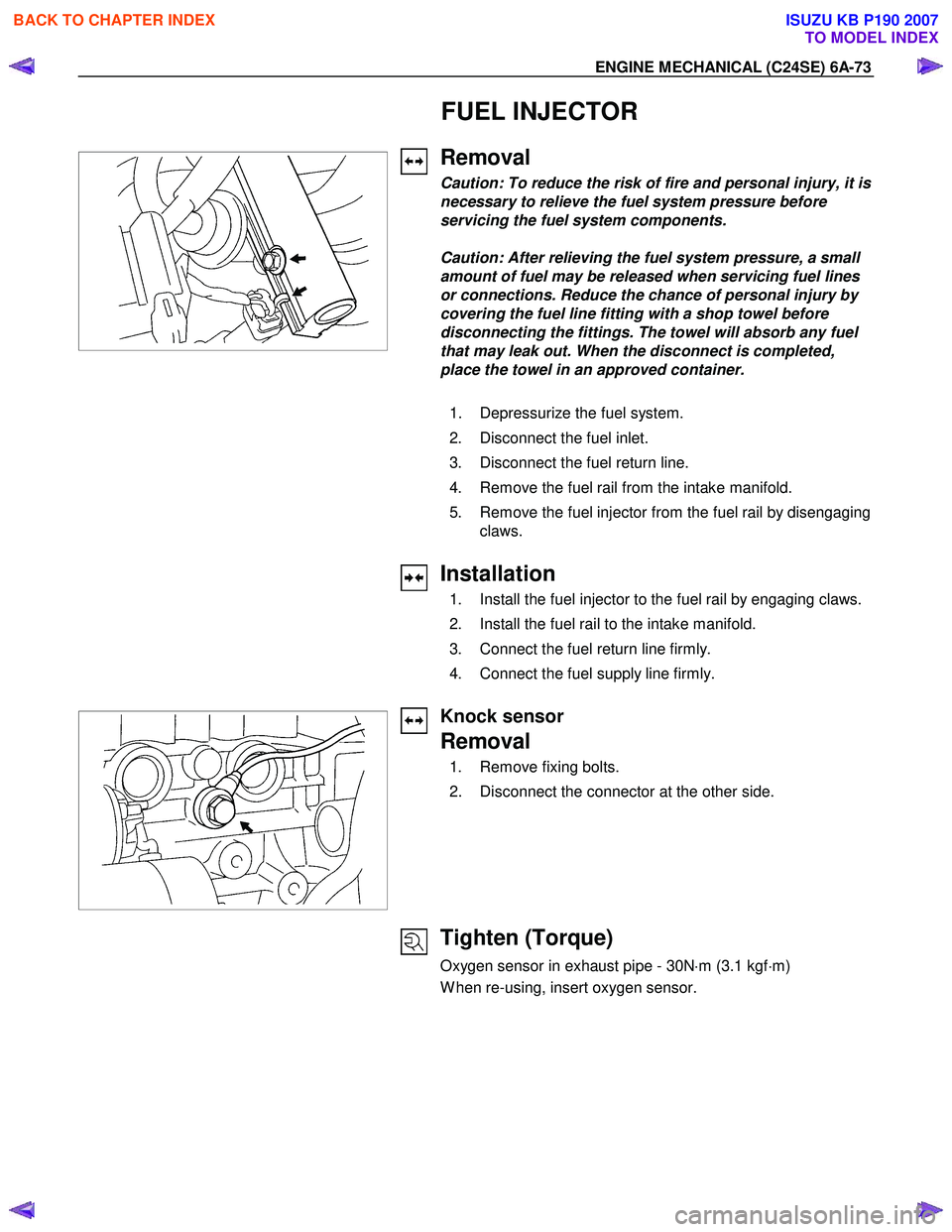
1. Depressurize the fuel system.
2. Disconnect the fuel inlet.
3. Disconnect the fuel return line.
4. Remove the fuel rail from the intake manifold.
5. Remove the fuel injector from the fuel rail by disengaging claws.
Installation
1. Install the fuel injector to the fuel rail by engaging claws.
2. Install the fuel rail to the intake manifold.
3. Connect the fuel return line firmly.
4. Connect the fuel supply line firmly.
Knock sensor
Removal
1. Remove fixing bolts.
2. Disconnect the connector at the other side.
Tighten (Torque)
Oxygen sensor in exhaust pipe - 30N ⋅m (3.1 kgf ⋅m)
W hen re-using, insert oxygen sensor.
BACK TO CHAPTER INDEX
TO MODEL INDEX
ISUZU KB P190 2007
Page 2122 of 6020
6C-4 ENGINE FUEL (C24SE)
Fuel Metering
Engine Control Module (ECM) is in complete control of this fuel
delivery system during normal driving conditions.
The intake manifold function, like that of a diesel, is used onl
y
to let air into the engine. The fuel is injected by separate
injectors that are mounted over the intake manifold.
The Manifold Absolute Pressure (MAP) sensor measures the
changes in the intake manifold pressure which result from
engine load and speed changes, which the MAP senso
r
converts to a voltage output.
This sensor generates the voltage to change corresponding to
the flow of the air drawn into the engine.
The changing voltage is transformed into an electric signal and
provided to the ECM.
W ith receipt of the signals sent from the MAP sensor, Intake
Air Temperature sensor and others, the ECM determines an
appropriate fuel injection pulse width feeding such information
to the fuel injector valves to effect an appropriate air/fuel ratio.
The Multiport Fuel Injection system utilizes an injection system
where the injectors turn on at every crankshaft revolution. The
ECM controls the injector on time so that the correct amount o
f
fuel is metered depending on driving conditions.
Two interchangeable "O" rings are used on the injector that
must be replaced when the injectors are removed.
The fuel rail is attached to the top of the intake manifold and
supplies fuel to all the injectors.
Fuel is recirculated through the rail continually while the engine
is running. This removes air and vapors from the fuel as well
as keeping the fuel cool during hot weather operation.
The fuel pressure control valve that is mounted on the fuel rail
maintains a pressure differential across the injectors under all
operating conditions. It is accomplished by controlling the
amount of fuel that is recirculated back to the fuel tank based
on engine demand.
See Section "Driveability and Emission" for more information
and diagnosis.
BACK TO CHAPTER INDEX
TO MODEL INDEX
ISUZU KB P190 2007
Page 2139 of 6020
6D1-2 ENGINE ELECTRICAL
Battery
General Description
There are six battery fluid caps on top of the battery.
These are covered by a paper label.
The battery is completely sealed except for the six small vent
holes on the side. These vent holes permit the escape of small
amounts of gas generated by the battery.
This type of battery has the following advantages over
conventional batteries:
1. There is no need to add water during the entire service life
of the battery.
2. The battery protects itself against overcharging.
The battery will refuse to accept an extensive charge.
(A conventional battery will accept an excessive charge, resulting in gassing and loss of battery fluid.)
3. The battery is much less vulnerable to self discharge than a conventional type battery.
Service Precaution
CAUTION:
Always use the correct fastener in the proper location.
When you replace a fastener, use ONLY the exact part
number for that application. ISUZU will call out those
fasteners that require a replacement after removal. ISUZU
will also call out the fasteners that require thread lockers
or thread sealant. UNLESS OTHERWISE SPECIFIED, do
not use supplemental coatings (Paints, greases, or other
corrosion inhibitors) on threaded fasteners or fastener
joint interfaces. Generally, such coatings adversely affect
the fastener torque and the joint clamping force, and may
damage the fastener. When you install fasteners, use the
correct tightening sequence and specifications. Following
these instructions can help you avoid damage to parts
and systems.
BACK TO CHAPTER INDEX
TO MODEL INDEX
ISUZU KB P190 2007