Page 5716 of 6020
9A1-34 RESTRAINT CONTROL SYSTEM
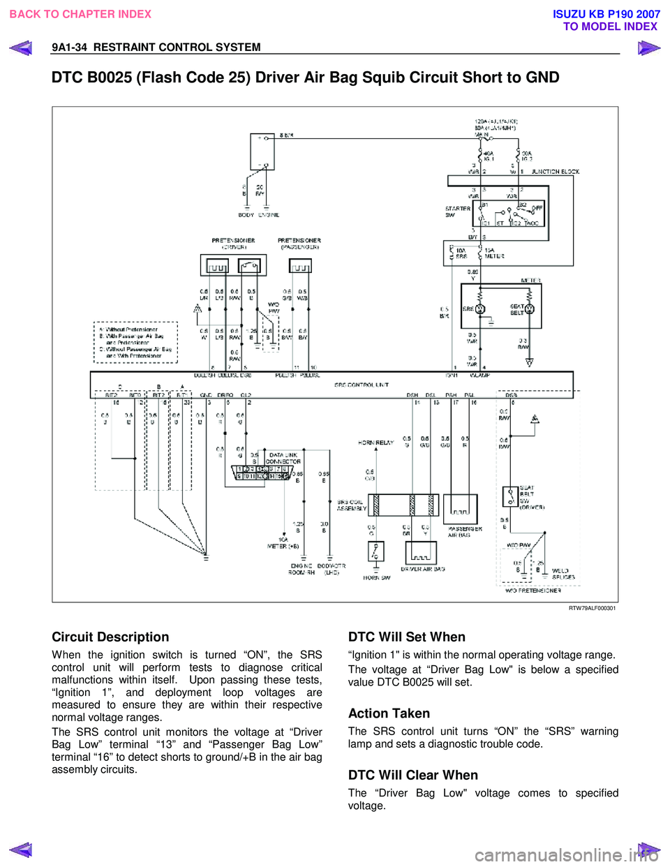
DTC B0025 (Flash Code 25) Driver Air Bag Squib Circuit Short to GND
RTW 79ALF000301
Circuit Description
W hen the ignition switch is turned “ON”, the SRS
control unit will perform tests to diagnose critical
malfunctions within itself. Upon passing these tests,
“Ignition 1”, and deployment loop voltages are
measured to ensure they are within their respective
normal voltage ranges.
The SRS control unit monitors the voltage at “Drive
r
Bag Low” terminal “13” and “Passenger Bag Low”
terminal “16” to detect shorts to ground/+B in the air bag
assembly circuits.
DTC Will Set When
“Ignition 1" is within the normal operating voltage range.
The voltage at “Driver Bag Low" is below a specified
value DTC B0025 will set.
Action Taken
The SRS control unit turns “ON” the “SRS” warning
lamp and sets a diagnostic trouble code.
DTC Will Clear When
The “Driver Bag Low" voltage comes to specified
voltage.
BACK TO CHAPTER INDEX TO MODEL INDEX
ISUZU KB P190 2007
Page 5719 of 6020
RESTRAINT CONTROL SYSTEM 9A1-37
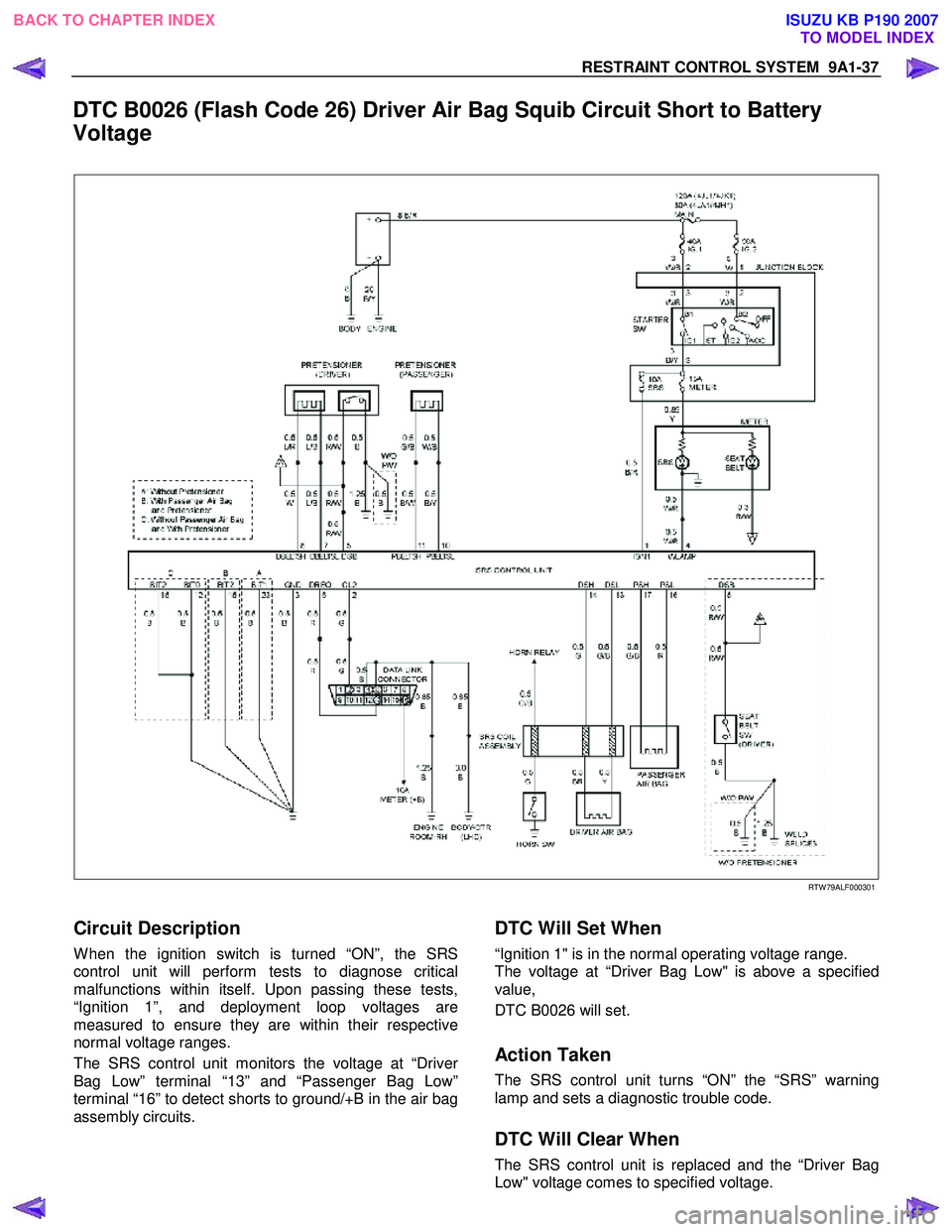
DTC B0026 (Flash Code 26) Driver Air Bag Squib Circuit Short to Battery
Voltage
RTW 79ALF000301
Circuit Description
W hen the ignition switch is turned “ON”, the SRS
control unit will perform tests to diagnose critical
malfunctions within itself. Upon passing these tests,
“Ignition 1”, and deployment loop voltages are
measured to ensure they are within their respective
normal voltage ranges.
The SRS control unit monitors the voltage at “Drive
r
Bag Low” terminal “13” and “Passenger Bag Low”
terminal “16” to detect shorts to ground/+B in the air bag
assembly circuits.
DTC Will Set When
“Ignition 1" is in the normal operating voltage range.
The voltage at “Driver Bag Low" is above a specified
value,
DTC B0026 will set.
Action Taken
The SRS control unit turns “ON” the “SRS” warning
lamp and sets a diagnostic trouble code.
DTC Will Clear When
The SRS control unit is replaced and the “Driver Bag
Low" voltage comes to specified voltage.
BACK TO CHAPTER INDEX TO MODEL INDEX
ISUZU KB P190 2007
Page 5722 of 6020
9A1-40 RESTRAINT CONTROL SYSTEM
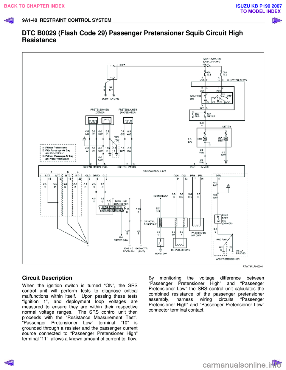
DTC B0029 (Flash Code 29) Passenger Pretensioner Squib Circuit High
Resistance
RTW 79ALF000301
Circuit Description
W hen the ignition switch is turned “ON”, the SRS
control unit will perform tests to diagnose critical
malfunctions within itself. Upon passing these tests
“Ignition 1”, and deployment loop voltages are
measured to ensure they are within their respective
normal voltage ranges. The SRS control unit then
proceeds with the “Resistance Measurement Test”.
“Passenger Pretensioner Low” terminal “10” is
grounded through a resister and the passenger current
source connected to “Passenger Pretensioner High”
terminal “11” allows a known amount of current to flow.
By monitoring the voltage difference between
“Passenger Pretensioner High” and “Passenger
Pretensioner Low” the SRS control unit calculates the
combined resistance of the passenger pretensione
r
assembly, harness wiring circuits “Passenger
Pretensioner High” and “Passenger Pretensioner Low”
connector terminal contact.
BACK TO CHAPTER INDEX TO MODEL INDEX
ISUZU KB P190 2007
Page 5725 of 6020
RESTRAINT CONTROL SYSTEM 9A1-43
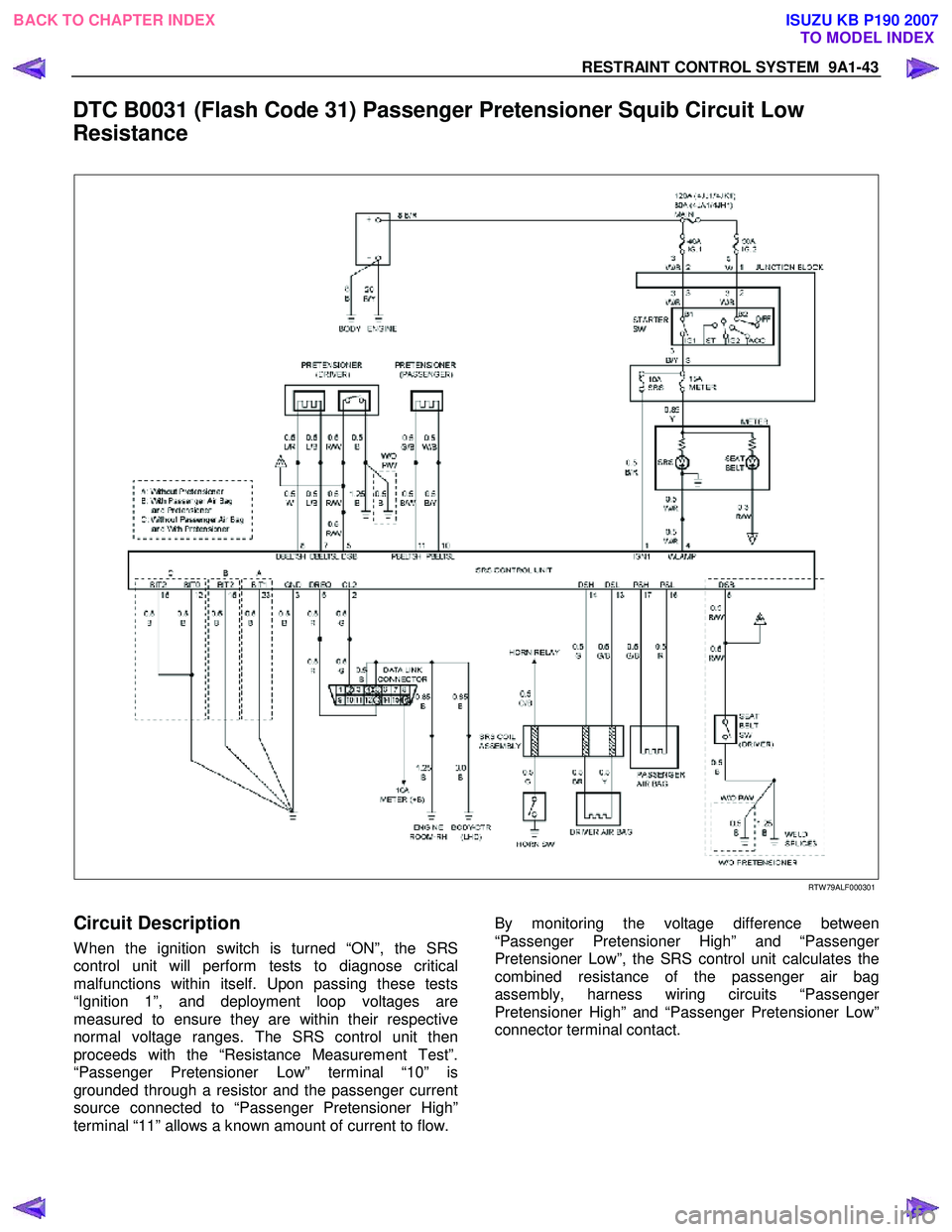
DTC B0031 (Flash Code 31) Passenger Pretensioner Squib Circuit Low
Resistance
RTW 79ALF000301
Circuit Description
W hen the ignition switch is turned “ON”, the SRS
control unit will perform tests to diagnose critical
malfunctions within itself. Upon passing these tests
“Ignition 1”, and deployment loop voltages are
measured to ensure they are within their respective
normal voltage ranges. The SRS control unit then
proceeds with the “Resistance Measurement Test”.
“Passenger Pretensioner Low” terminal “10” is
grounded through a resistor and the passenger current
source connected to “Passenger Pretensioner High”
terminal “11” allows a known amount of current to flow.
By monitoring the voltage difference between
“Passenger Pretensioner High” and “Passenger
Pretensioner Low”, the SRS control unit calculates the
combined resistance of the passenger air bag
assembly, harness wiring circuits “Passenge
r
Pretensioner High” and “Passenger Pretensioner Low”
connector terminal contact.
BACK TO CHAPTER INDEX TO MODEL INDEX
ISUZU KB P190 2007
Page 5728 of 6020
9A1-46 RESTRAINT CONTROL SYSTEM
DTC B0033 (Flash Code 33) Passenger Pretensioner Squib Circuit Short to
GND
RTW 79ALF000301
Circuit Description
W hen the ignition switch is turned “ON”, the SRS
control unit will perform tests to diagnose critical
malfunctions within itself. Upon passing these tests,
“Ignition 1”, and pretensioner loop voltages are
measured to ensure they are within their respective
normal voltage ranges.
The SRS control unit monitors the voltages at “Drive
r
Pretensioner Low” terminal “7” and “Passenger
Pretensioner Low” terminal “10” to detect short to
ground/+B in the pretensioner assembly circuits.
DTC Will Set When
“Ignition 1" is in the normal operating voltage range.
The voltage at “Passenger Pretensioner Low " is belo
w
a specified value,
DTC B0033 will set.
Action Taken
SRS control unit turns “ON” the “SRS” warning lamp
and sets a diagnostic trouble code.
BACK TO CHAPTER INDEX TO MODEL INDEX
ISUZU KB P190 2007
Page 5731 of 6020
RESTRAINT CONTROL SYSTEM 9A1-49
DTC B0034 (Flash Code 34) Passenger Pretensioner Squib Circuit Short to
Battery Voltage
RTW 79ALF000301
Circuit Description
W hen the ignition switch is turned “ON”, the SRS
control unit will perform tests to diagnose critical
malfunctions within itself. Upon passing these tests,
“Ignition 1”, and pretensioner loop voltages are
measured to ensure they are within their respective
normal voltage ranges.
The SRS control unit monitors the voltages at “Drive
r
Pretensioner Low” terminal “7” and “Passenger
Pretensioner Low” terminal “10” to detect short to
ground/+B in the pretensioner assembly circuits.
DTC Will Set When
“Ignition 1" is in the normal operating voltage range.
The voltage at “Passenger Pretensioner Low " is above
a specified value,
DTC B0034 will set.
Action Taken
SRS control unit turns “ON” the “SRS” warning lamp
and sets a diagnostic trouble code.
BACK TO CHAPTER INDEX TO MODEL INDEX
ISUZU KB P190 2007
Page 5733 of 6020
RESTRAINT CONTROL SYSTEM 9A1-51
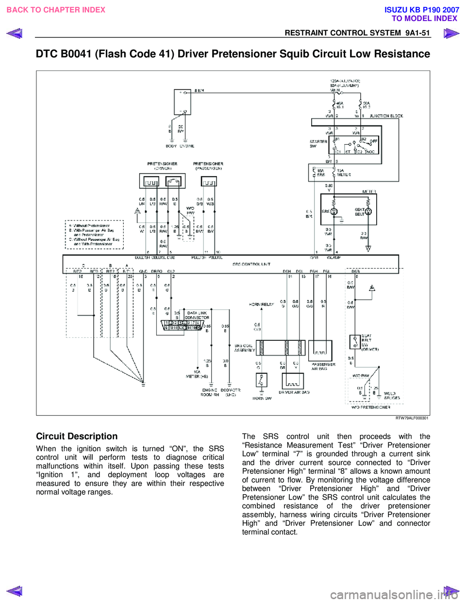
DTC B0041 (Flash Code 41) Driver Pretensioner Squib Circuit Low Resistance
RTW 79ALF000301
Circuit Description
W hen the ignition switch is turned “ON”, the SRS
control unit will perform tests to diagnose critical
malfunctions within itself. Upon passing these tests
“Ignition 1”, and deployment loop voltages are
measured to ensure they are within their respective
normal voltage ranges.
The SRS control unit then proceeds with the
“Resistance Measurement Test” “Driver Pretensioner
Low” terminal “7” is grounded through a current sink
and the driver current source connected to “Drive
r
Pretensioner High” terminal “8” allows a known amount
of current to flow. By monitoring the voltage difference
between “Driver Pretensioner High” and “Drive
r
Pretensioner Low” the SRS control unit calculates the
combined resistance of the driver pretensione
r
assembly, harness wiring circuits “Driver Pretensioner
High” and “Driver Pretensioner Low” and connector
terminal contact.
BACK TO CHAPTER INDEX TO MODEL INDEX
ISUZU KB P190 2007
Page 5736 of 6020

9A1-54 RESTRAINT CONTROL SYSTEM
DTC B0042 (Flash Code 42) Driver Pretensioner Squib Circuit High
Resistance
RTW 79ALF000301
Circuit Description
W hen the ignition switch is turned “ON”, the SRS
control unit will perform tests to diagnose critical
malfunctions within itself. Upon passing these tests,
“Ignition 1”, and deployment loop voltages are
measured to ensure they are within their respective
normal voltage ranges.
The SRS control unit then proceeds with the
“Resistance Measurement Test” “Driver Pretensioner
Low” terminal “7” is grounded through a current sink
and the driver current source connected to “Drive
r
Pretensioner High” terminal “8” allows a known amount
of current to flow. By monitoring the voltage difference
between “Driver Pretensioner High” and “Drive
r
Pretensioner Low”, the SRS control unit calculates the
combined resistance of the driver pretensione
r
assembly, SRS coil assembly, harness wiring circuits
“Driver Pretensioner High” and “Driver Pretensione
r
Low” and connector terminal contact.
BACK TO CHAPTER INDEX TO MODEL INDEX
ISUZU KB P190 2007