2007 ISUZU KB P190 ESP
[x] Cancel search: ESPPage 4751 of 6020
7B1-32 Manual Transmission (MUX)
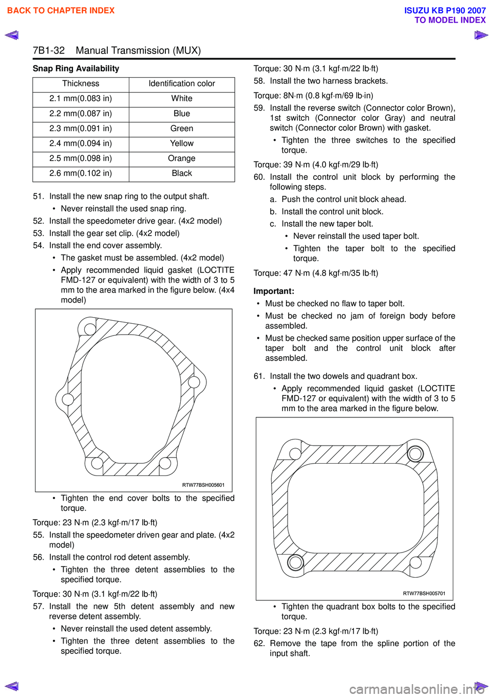
Snap Ring Availability51. Install the new snap ring to the output shaft. • Never reinstall the used snap ring.
52. Install the speedometer drive gear. (4x2 model)
53. Install the gear set clip. (4x2 model)
54. Install the end cover assembly.
• The gasket must be assembled. (4x2 model)
• Apply recommended liquid gasket (LOCTITE FMD-127 or equivalent) with the width of 3 to 5
mm to the area marked in the figure below. (4x4
model)
• Tighten the end cover bolts to the specified torque.
Torque: 23 N ⋅m (2.3 kgf ⋅m/17 lb ⋅ft)
55. Install the speedometer driven gear and plate. (4x2 model)
56. Install the control rod detent assembly.
• Tighten the three detent assemblies to thespecified torque.
Torque: 30 N ⋅m (3.1 kgf ⋅m/22 lb ⋅ft)
57. Install the new 5th detent assembly and new reverse detent assembly.
• Never reinstall the used detent assembly.
• Tighten the three detent assemblies to the specified torque. Torque: 30 N
⋅m (3.1 kgf ⋅m/22 lb ⋅ft)
58. Install the two harness brackets.
Torque: 8N ⋅m (0.8 kgf ⋅m/69 lb ⋅in)
59. Install the reverse switch (Connector color Brown), 1st switch (Connector color Gray) and neutral
switch (Connector color Brown) with gasket.
• Tighten the three switches to the specified torque.
Torque: 39 N ⋅m (4.0 kgf ⋅m/29 lb ⋅ft)
60. Install the control unit block by performing the following steps.
a. Push the control unit block ahead.
b. Install the control unit block.
c. Install the new taper bolt.
• Never reinstall the used taper bolt.
• Tighten the taper bolt to the specified torque.
Torque: 47 N ⋅m (4.8 kgf ⋅m/35 lb ⋅ft)
Important: • Must be checked no flaw to taper bolt.
• Must be checked no jam of foreign body before assembled.
• Must be checked same position upper surface of the taper bolt and the control unit block after
assembled.
61. Install the two dowels and quadrant box. • Apply recommended liquid gasket (LOCTITEFMD-127 or equivalent) with the width of 3 to 5
mm to the area marked in the figure below.
• Tighten the quadrant box bolts to the specified torque.
Torque: 23 N ⋅m (2.3 kgf ⋅m/17 lb ⋅ft)
62. Remove the tape from the spline portion of the input shaft.
Thickness
Identification color
2.1 mm(0.083 in) White
2.2 mm(0.087 in) Blue
2.3 mm(0.091 in) Green
2.4 mm(0.094 in) Yellow
2.5 mm(0.098 in) Orange
2.6 mm(0.102 in) Black
RTW77BSH005601
RTW77BSH005701
BACK TO CHAPTER INDEX
TO MODEL INDEX
ISUZU KB P190 2007
Page 4773 of 6020
7B1-54 Manual Transmission (MUX)
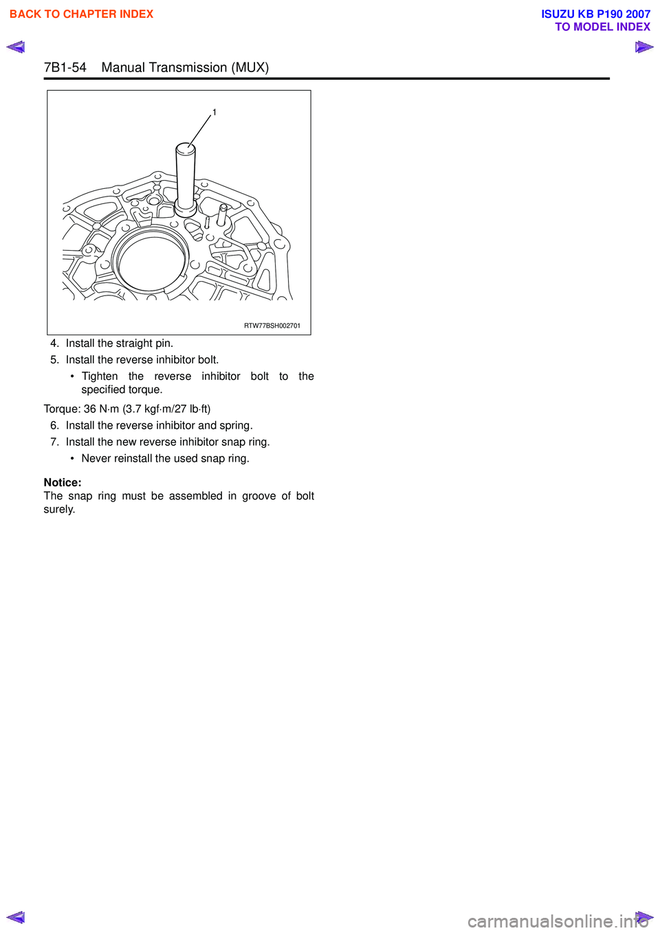
4. Install the straight pin.
5. Install the reverse inhibitor bolt.
• Tighten the reverse inhibitor bolt to thespecified torque.
Torque: 36 N ⋅m (3.7 kgf ⋅m/27 lb ⋅ft)
6. Install the reverse inhibitor and spring.
7. Install the new reverse inhibitor snap ring.
• Never reinstall the used snap ring.
Notice:
The snap ring must be assembled in groove of bolt
surely.
RTW77BSH002701
1
BACK TO CHAPTER INDEX
TO MODEL INDEX
ISUZU KB P190 2007
Page 4929 of 6020
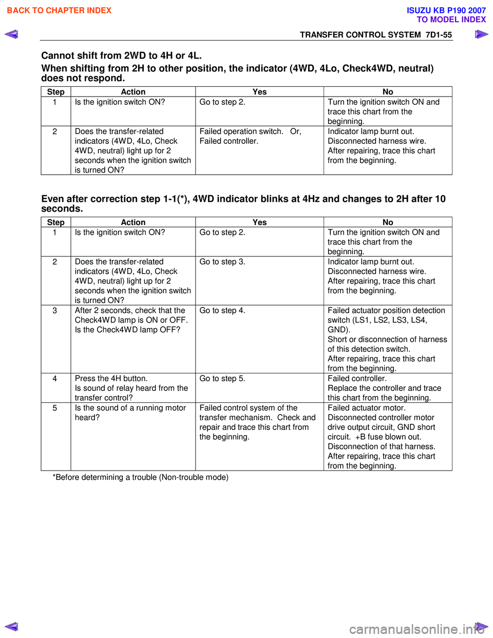
TRANSFER CONTROL SYSTEM 7D1-55
Cannot shift from 2WD to 4H or 4L.
When shifting from 2H to other position, the indicator (4WD, 4Lo, Check4WD, neutral)
does not respond.
Step Action Yes No
1 Is the ignition switch ON? Go to step 2.
Turn the ignition switch ON and
trace this chart from the
beginning.
2 Does the transfer-related
indicators (4W D, 4Lo, Check
4W D, neutral) light up for 2
seconds when the ignition switch
is turned ON? Failed operation switch. Or,
Failed controller. Indicator lamp burnt out.
Disconnected harness wire.
After repairing, trace this chart
from the beginning.
Even after correction step 1-1(*), 4WD indicator blinks at 4Hz and changes to 2H after 10
seconds.
Step Action Yes No
1 Is the ignition switch ON? Go to step 2.
Turn the ignition switch ON and
trace this chart from the
beginning.
2 Does the transfer-related
indicators (4W D, 4Lo, Check
4W D, neutral) light up for 2
seconds when the ignition switch
is turned ON? Go to step 3.
Indicator lamp burnt out.
Disconnected harness wire.
After repairing, trace this chart
from the beginning.
3 After 2 seconds, check that the
Check4W D lamp is ON or OFF.
Is the Check4W D lamp OFF? Go to step 4.
Failed actuator position detection
switch (LS1, LS2, LS3, LS4,
GND).
Short or disconnection of harness
of this detection switch.
After repairing, trace this chart
from the beginning.
4 Press the 4H button.
Is sound of relay heard from the
transfer control? Go to step 5.
Failed controller.
Replace the controller and trace
this chart from the beginning.
5 Is the sound of a running motor
heard? Failed control system of the
transfer mechanism. Check and
repair and trace this chart from
the beginning. Failed actuator motor.
Disconnected controller motor
drive output circuit, GND short
circuit. +B fuse blown out.
Disconnection of that harness.
After repairing, trace this chart
from the beginning.
*Before determining a trouble (Non-trouble mode)
BACK TO CHAPTER INDEX
TO MODEL INDEX
ISUZU KB P190 2007
Page 4932 of 6020
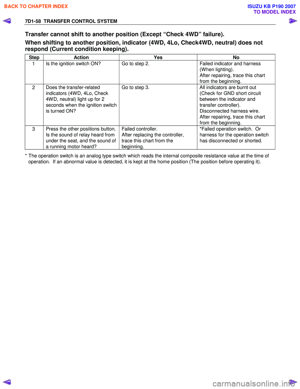
7D1-58 TRANSFER CONTROL SYSTEM
Transfer cannot shift to another position (Except “Check 4WD” failure).
When shifting to another position, indicator (4WD, 4Lo, Check4WD, neutral) does not
respond (Current condition keeping).
Step Action Yes No
1 Is the ignition switch ON? Go to step 2.
Failed indicator and harness
(W hen lighting).
After repairing, trace this chart
from the beginning.
2 Does the transfer-related
indicators (4W D, 4Lo, Check
4W D, neutral) light up for 2
seconds when the ignition switch
is turned ON? Go to step 3.
All indicators are burnt out
(Check for GND short circuit
between the indicator and
transfer controller).
Disconnected harness wire.
After repairing, trace this chart
from the beginning.
3 Press the other positions button.
Is the sound of relay heard from
under the seat, and the sound of
a running motor heard? Failed controller.
After replacing the controller,
trace this chart from the
beginning. *Failed operation switch. Or
harness for the operation switch
has disconnected or shorted.
* The operation switch is an analog type switch which reads the internal composite resistance value at the time of operation. If an abnormal value is detected, it is kept at the home position (The position before operating it).
BACK TO CHAPTER INDEX
TO MODEL INDEX
ISUZU KB P190 2007
Page 4934 of 6020
7D1-60 TRANSFER CONTROL SYSTEM
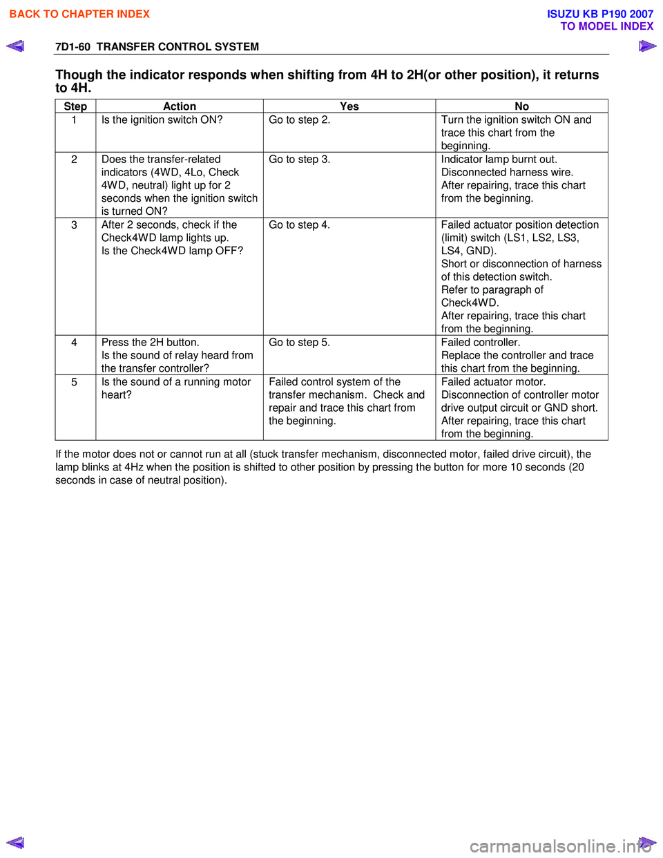
Though the indicator responds when shifting from 4H to 2H(or other position), it returns
to 4H.
Step Action Yes No
1 Is the ignition switch ON? Go to step 2.
Turn the ignition switch ON and
trace this chart from the
beginning.
2 Does the transfer-related
indicators (4W D, 4Lo, Check
4W D, neutral) light up for 2
seconds when the ignition switch
is turned ON? Go to step 3.
Indicator lamp burnt out.
Disconnected harness wire.
After repairing, trace this chart
from the beginning.
3 After 2 seconds, check if the
Check4W D lamp lights up.
Is the Check4W D lamp OFF? Go to step 4.
Failed actuator position detection
(limit) switch (LS1, LS2, LS3,
LS4, GND).
Short or disconnection of harness
of this detection switch.
Refer to paragraph of
Check4W D.
After repairing, trace this chart
from the beginning.
4 Press the 2H button.
Is the sound of relay heard from
the transfer controller? Go to step 5.
Failed controller.
Replace the controller and trace
this chart from the beginning.
5 Is the sound of a running motor
heart? Failed control system of the
transfer mechanism. Check and
repair and trace this chart from
the beginning. Failed actuator motor.
Disconnection of controller motor
drive output circuit or GND short.
After repairing, trace this chart
from the beginning.
If the motor does not or cannot run at all (stuck transfer mechanism, disconnected motor, failed drive circuit), the
lamp blinks at 4Hz when the position is shifted to other position by pressing the button for more 10 seconds (20
seconds in case of neutral position).
BACK TO CHAPTER INDEX
TO MODEL INDEX
ISUZU KB P190 2007
Page 4956 of 6020
8A-18 ELECTRICAL-BODY AND CHASSIS
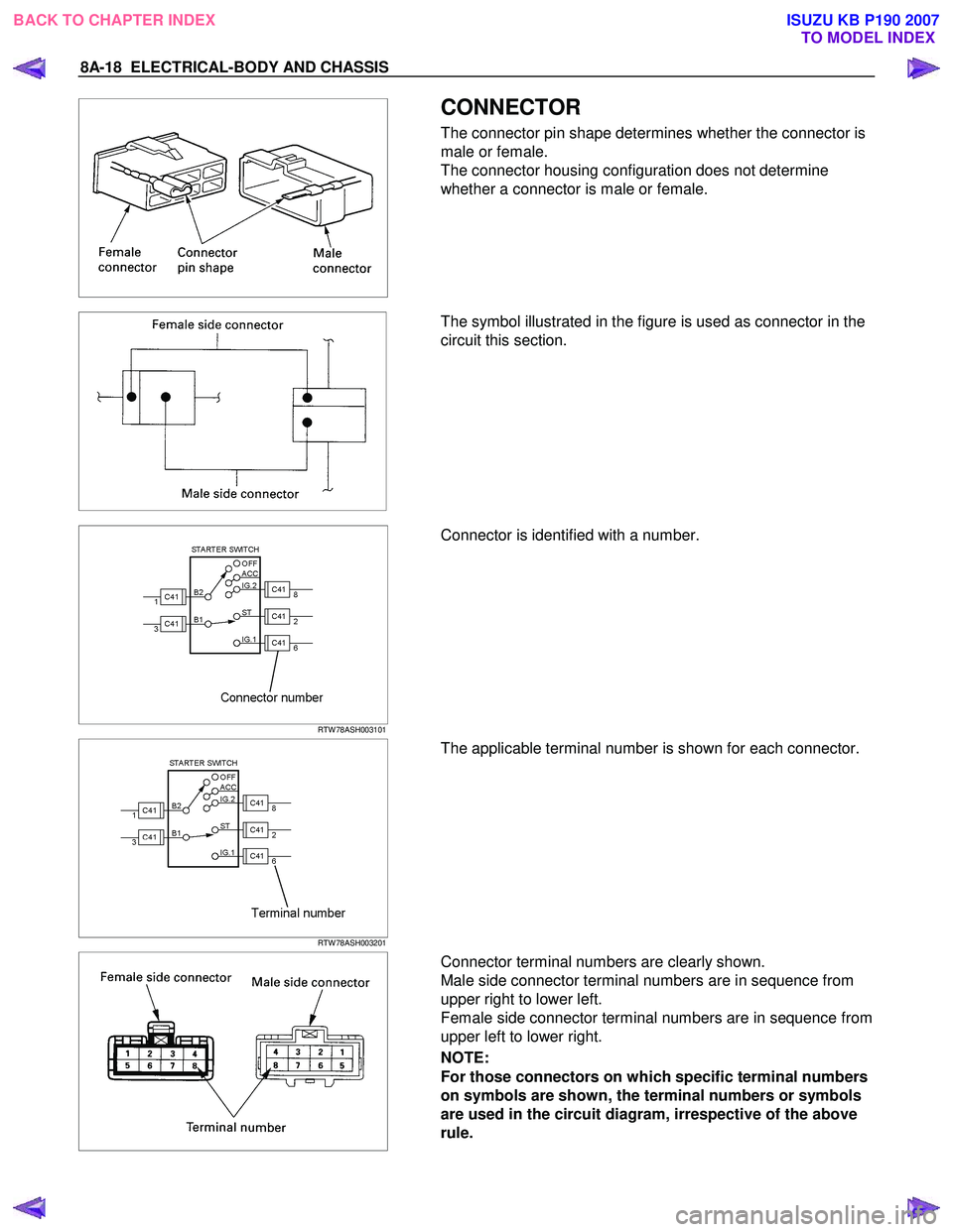
CONNECTOR
The connector pin shape determines whether the connector is
male or female.
The connector housing configuration does not determine
whether a connector is male or female.
The symbol illustrated in the figure is used as connector in the
circuit this section.
RTW 78ASH003101
Connector is identified with a number.
RTW 78ASH003201
The applicable terminal number is shown for each connector.
Connector terminal numbers are clearly shown.
Male side connector terminal numbers are in sequence from
upper right to lower left.
Female side connector terminal numbers are in sequence from
upper left to lower right.
NOTE:
For those connectors on which specific terminal numbers
on symbols are shown, the terminal numbers or symbols
are used in the circuit diagram, irrespective of the above
rule.
BACK TO CHAPTER INDEX TO MODEL INDEXISUZU KB P190 2007
Page 5585 of 6020
Cruise Control – HFV6 Page 8C–7
Activated and Deactivated
When the cruise control is enabled, the vehicle speed must be above 40 km/h and the cruise control switch assembly
pressed to SET–COAST, the cruise control will be activated and the vehicle will maintain the set speed. When
deactivated by the methods described within this section, the vehicle will no longer maintain the set speed, but the cruise
control will still be engaged.
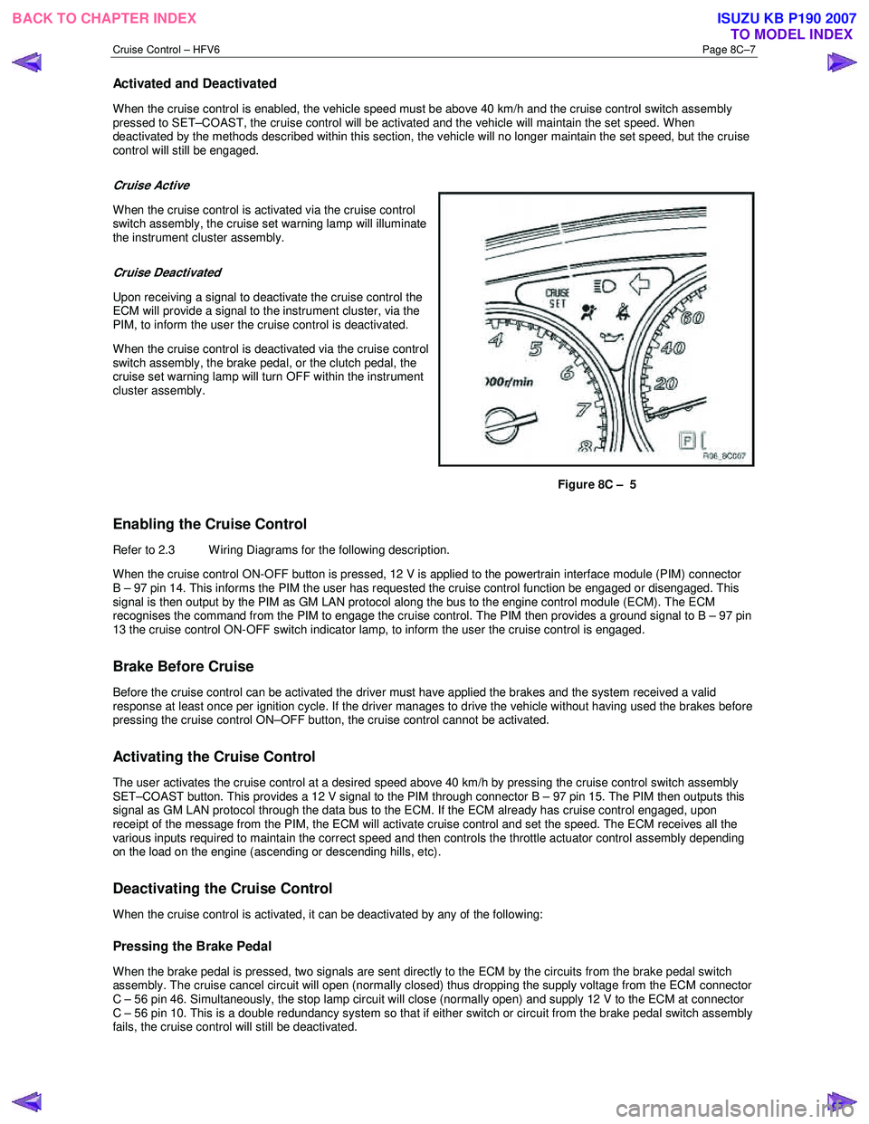
Cruise Active
When the cruise control is activated via the cruise control
switch assembly, the cruise set warning lamp will illuminate
the instrument cluster assembly.
Cruise Deactivated
Upon receiving a signal to deactivate the cruise control the
ECM will provide a signal to the instrument cluster, via the
PIM, to inform the user the cruise control is deactivated.
When the cruise control is deactivated via the cruise control
switch assembly, the brake pedal, or the clutch pedal, the
cruise set warning lamp will turn OFF within the instrument
cluster assembly.
Figure 8C – 5
Enabling the Cruise Control
Refer to 2.3 Wiring Diagrams for the following description.
W hen the cruise control ON-OFF button is pressed, 12 V is applied to the powertrain interface module (PIM) connector
B – 97 pin 14. This informs the PIM the user has requested the cruise control function be engaged or disengaged. This
signal is then output by the PIM as GM LAN protocol along the bus to the engine control module (ECM). The ECM
recognises the command from the PIM to engage the cruise control. The PIM then provides a ground signal to B – 97 pin
13 the cruise control ON-OFF switch indicator lamp, to inform the user the cruise control is engaged.
Brake Before Cruise
Before the cruise control can be activated the driver must have applied the brakes and the system received a valid
response at least once per ignition cycle. If the driver manages to drive the vehicle without having used the brakes before
pressing the cruise control ON–OFF button, the cruise control cannot be activated.
Activating the Cruise Control
The user activates the cruise control at a desired speed above 40 km/h by pressing the cruise control switch assembly
SET–COAST button. This provides a 12 V signal to the PIM through connector B – 97 pin 15. The PIM then outputs this
signal as GM LAN protocol through the data bus to the ECM. If the ECM already has cruise control engaged, upon
receipt of the message from the PIM, the ECM will activate cruise control and set the speed. The ECM receives all the
various inputs required to maintain the correct speed and then controls the throttle actuator control assembly depending
on the load on the engine (ascending or descending hills, etc).
Deactivating the Cruise Control
When the cruise control is activated, it can be deactivated by any of the following:
Pressing the Brake Pedal
When the brake pedal is pressed, two signals are sent directly to the ECM by the circuits from the brake pedal switch
assembly. The cruise cancel circuit will open (normally closed) thus dropping the supply voltage from the ECM connector
C – 56 pin 46. Simultaneously, the stop lamp circuit will close (normally open) and supply 12 V to the ECM at connector
C – 56 pin 10. This is a double redundancy system so that if either switch or circuit from the brake pedal switch assembly
fails, the cruise control will still be deactivated.
BACK TO CHAPTER INDEX TO MODEL INDEXISUZU KB P190 2007
Page 5690 of 6020
9A1-8 RESTRAINT CONTROL SYSTEM
Circuit Description
W hen the ignition switch is first turned “ON”, “Ignition 1”
voltage is applied from the “SRS” fuse to the SRS
control unit at the “Ignition 1” input terminals “1”. The
SRS control unit responds by flashing the “SRS”
warning lamp seven times, while performing tests on
the SRS.
Notes On System Check Chart
1. The “SRS” warning lamp should flash seven times after the ignition is first turned “ON”.
2.
After the “SRS” warning lamp flashes seven times, it
should turn to “LOCK”
3. This test checks for the proper operation of the “Serial Data” line. This test will also determine
whether history diagnostic trouble codes are stored
and, if so, identify them.
4. Improper operation of the “SRS” warning lamp is indicated. This test differentiates between ‘a
warning lamp stays “ON” condition’ and ‘a warning
lamp does not come “ON” condition’.
5. This test checks for proper operation of the “Serial Data” line. This test will also identify the stored
diagnostic trouble codes and whether they are
current or history.
Diagnostic Aids
The order in which diagnostic trouble codes are
diagnosed is very important. Failure to diagnose the
diagnostic trouble codes in the order specified ma
y
result in extended diagnostic time, incorrect diagnosis
and incorrect parts replacement.
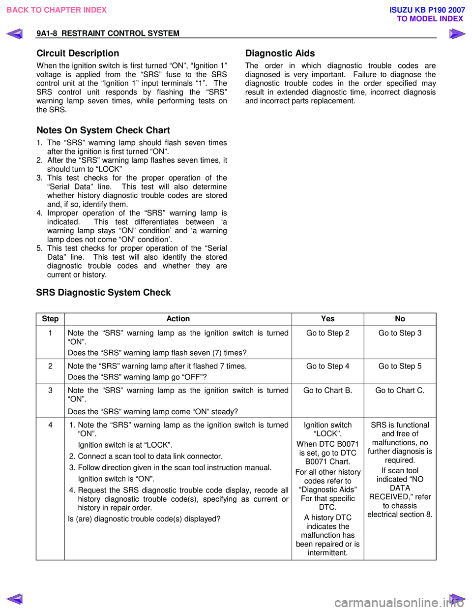
SRS Diagnostic System Check
Step Action Yes No
1 Note the “SRS” warning lamp as the ignition switch is turned
“ON”.
Does the “SRS” warning lamp flash seven (7) times? Go to Step 2 Go to Step 3
2 Note the “SRS” warning lamp after it flashed 7 times.
Does the “SRS” warning lamp go “OFF”? Go to Step 4 Go to Step 5
3 Note the “SRS” warning lamp as the ignition switch is turned
“ON”.
Does the “SRS” warning lamp come “ON” steady? Go to Chart B. Go to Chart C.
4
1. Note the “SRS” warning lamp as the ignition switch is turned
“ON”.
Ignition switch is at “LOCK”.
2. Connect a scan tool to data link connector.
3. Follow direction given in the scan tool instruction manual.
Ignition switch is “ON”.
4. Request the SRS diagnostic trouble code display, recode all
history diagnostic trouble code(s), specifying as current or
history in repair order.
Is (are) diagnostic trouble code(s) displayed?
Ignition switch
“LOCK”.
W hen DTC B0071 is set, go to DTC B0071 Chart.
For all other history codes refer to
“Diagnostic Aids” For that specific DTC.
A history DTC indicates the
malfunction has
been repaired or is intermittent. SRS is functional
and free of
malfunctions, no
further diagnosis is required.
If scan tool
indicated “NO DATA
RECEIVED,” refer to chassis
electrical section 8.
BACK TO CHAPTER INDEX TO MODEL INDEX
ISUZU KB P190 2007