2007 ISUZU KB P190 ESP
[x] Cancel search: ESPPage 4395 of 6020
TRANSMISSION CONTROL SYSTEM (JR405E) 7A2-111
D2: Gearshift Frequently
Diagnosis Hints• When inspecting faulty gear shifting, it is important to distinguish between
the fault of the electric system and transmission main unit.
• Fault of electric system. - Monitor the output signal (each solenoid driving signal) using a scan tool. If a trouble signal is sent to the solenoid synchronously with the faulty
gear shifting, the fault is originated in the electric system.
- Monitor the input signal (signal from each sensor) using a scan tool and find an input signal which has an output signal (each solenoid driving
signal) subjected to a fault.
- Fault of the electric system may be derived from temperature or vibration. For instance, although the engine is normal while it is cold, fault may
occur when the engine is warmed up or the vehicle is running.
• Fault of mechanical system. - If the gear is incorrectly shifted, irrespective of the operating signal (On/ Off) of each solenoid, the fault is originated from the transmission main
unit.
- If the clutch slips, or the transmission fluid smells burnt or is contaminated or black, or the stall speed increases. Gear ratio error DTC might be set.
Transmission Range Switch & Selector
Lever Cable Checks Inspect the transmission range switch and selector lever cable for misadjusting
or disordering. Refer to On-Vehicle Service section.
Transmission Fluid Checks Inspect the transmission fluid for the following conditions. If the transmission fluid
is extremely blacked, contaminated or smells burnt, slipping of clutch is
suspected.
• Low quantity
• Contamination
•Smell
Line Pressure Checks Inspect the line pressure in forward ranges for a possible dropped pressure.
Refer to Line Pressure Test in Test Instruction section.
Stall Speed Checks Inspect the stall speed in forward ranges. Refer to Stall Test in Test Instruction
section.
Control Valve Body Checks Inspect the valve body for the following conditions.
• Faulty operation
• Sticking spool valve
• Sticking shift solenoid valve. Perform function check. Refer to On-Vehicle Service section.
• Faulty operation of transmission fluid pressure switch. Perform function check. Refer to On-Vehicle Service section.
• Clogged hydraulic circuit
Checks
Action
Checks Action
Definition:
Shift down or engine overrun occurs above than kick-down area.
Diagnosis Hints The same causes as in category No. “C1 - C8: Engine Race Up (Slipping)” are
suspected.
BACK TO CHAPTER INDEX
TO MODEL INDEX
ISUZU KB P190 2007
Page 4432 of 6020
7A2-148 TRANSMISSION CONTROL SYSTEM (JR405E)
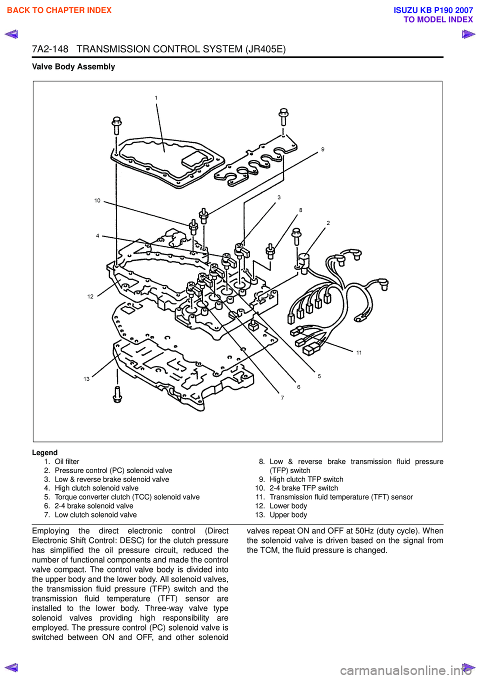
Valve Body Assembly
Legend1. Oil filter
2. Pressure control (PC) solenoid valve
3. Low & reverse brake solenoid valve
4. High clutch solenoid valve
5. Torque converter clutch (TCC) solenoid valve
6. 2-4 brake solenoid valve
7. Low clutch solenoid valve 8. Low & reverse brake transmission fluid pressure
(TFP) switch
9. High clutch TFP switch
10. 2-4 brake TFP switch
11. Transmission fluid temperature (TFT) sensor
12. Lower body
13. Upper body
Employing the direct electronic control (Direct
Electronic Shift Control: DESC) for the clutch pressure
has simplified the oil pressure circuit, reduced the
number of functional components and made the control
valve compact. The control valve body is divided into
the upper body and the lower body. All solenoid valves,
the transmission fluid pressure (TFP) switch and the
transmission fluid temperature (TFT) sensor are
installed to the lower body. Three-way valve type
solenoid valves providing high responsibility are
employed. The pressure control (PC) solenoid valve is
switched between ON and OFF, and other solenoid valves repeat ON and OFF at 50Hz (duty cycle). When
the solenoid valve is driven based on the signal from
the TCM, the fluid pressure is changed.
BACK TO CHAPTER INDEX
TO MODEL INDEX
ISUZU KB P190 2007
Page 4433 of 6020
TRANSMISSION CONTROL SYSTEM (JR405E) 7A2-149
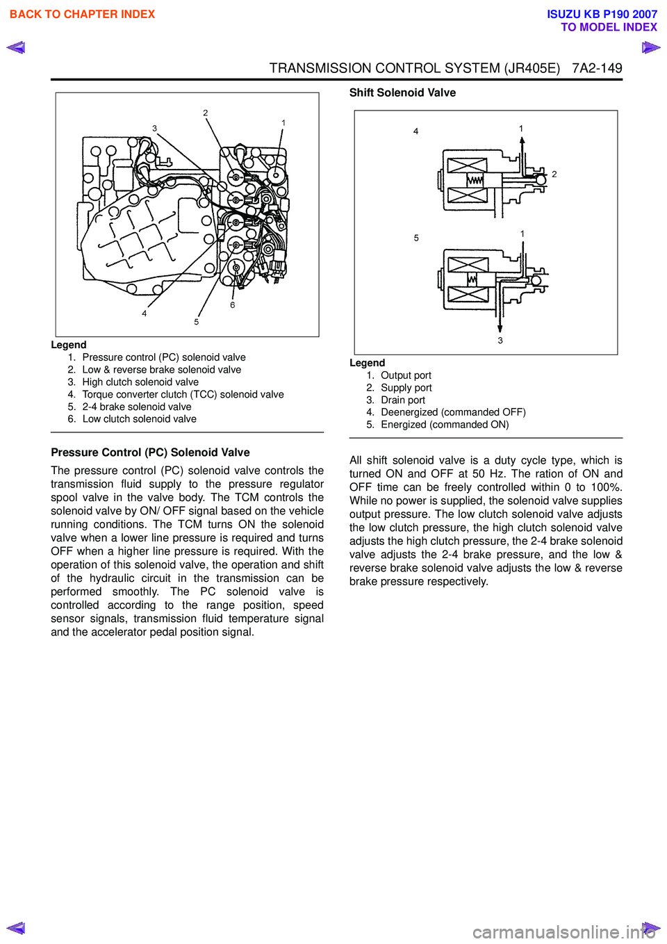
Legend1. Pressure control (PC) solenoid valve
2. Low & reverse brake solenoid valve
3. High clutch solenoid valve
4. Torque converter clutch (TCC) solenoid valve
5. 2-4 brake solenoid valve
6. Low clutch solenoid valve
Pressure Control (PC) Solenoid Valve
The pressure control (PC) solenoid valve controls the
transmission fluid supply to the pressure regulator
spool valve in the valve body. The TCM controls the
solenoid valve by ON/ OFF signal based on the vehicle
running conditions. The TCM turns ON the solenoid
valve when a lower line pressure is required and turns
OFF when a higher line pressure is required. With the
operation of this solenoid valve, the operation and shift
of the hydraulic circuit in the transmission can be
performed smoothly. The PC solenoid valve is
controlled according to the range position, speed
sensor signals, transmission fluid temperature signal
and the accelerator pedal position signal. Shift Solenoid Valve
Legend
1. Output port
2. Supply port
3. Drain port
4. Deenergized (commanded OFF)
5. Energized (commanded ON)
All shift solenoid valve is a duty cycle type, which is
turned ON and OFF at 50 Hz. The ration of ON and
OFF time can be freely controlled within 0 to 100%.
While no power is supplied, the solenoid valve supplies
output pressure. The low clutch solenoid valve adjusts
the low clutch pressure, the high clutch solenoid valve
adjusts the high clutch pressure, the 2-4 brake solenoid
valve adjusts the 2-4 brake pressure, and the low &
reverse brake solenoid valve adjusts the low & reverse
brake pressure respectively.
BACK TO CHAPTER INDEX
TO MODEL INDEX
ISUZU KB P190 2007
Page 4434 of 6020
7A2-150 TRANSMISSION CONTROL SYSTEM (JR405E)
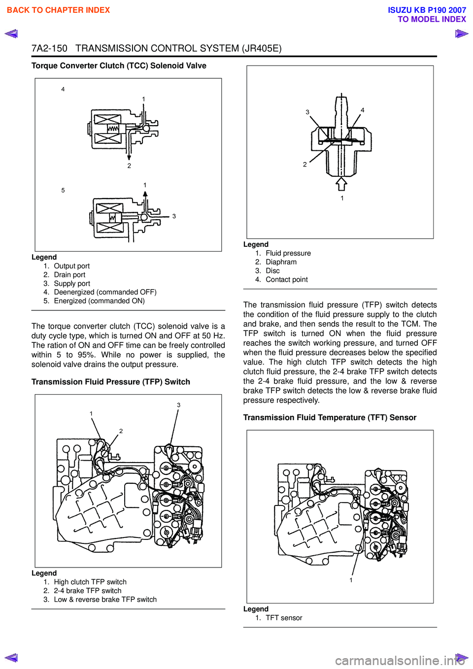
Torque Converter Clutch (TCC) Solenoid Valve
Legend1. Output port
2. Drain port
3. Supply port
4. Deenergized (commanded OFF)
5. Energized (commanded ON)
The torque converter clutch (TCC) solenoid valve is a
duty cycle type, which is turned ON and OFF at 50 Hz.
The ration of ON and OFF time can be freely controlled
within 5 to 95%. While no power is supplied, the
solenoid valve drains the output pressure.
Transmission Fluid Pressure (TFP) Switch
Legend 1. High clutch TFP switch
2. 2-4 brake TFP switch
3. Low & reverse brake TFP switch
Legend
1. Fluid pressure
2. Diaphram
3. Disc
4. Contact point
The transmission fluid pressure (TFP) switch detects
the condition of the fluid pressure supply to the clutch
and brake, and then sends the result to the TCM. The
TFP switch is turned ON when the fluid pressure
reaches the switch working pressure, and turned OFF
when the fluid pressure decreases below the specified
value. The high clutch TFP switch detects the high
clutch fluid pressure, the 2-4 brake TFP switch detects
the 2-4 brake fluid pressure, and the low & reverse
brake TFP switch detects the low & reverse brake fluid
pressure respectively.
Transmission Fluid Temperature (TFT) Sensor
Legend
1. TFT sensor
BACK TO CHAPTER INDEX
TO MODEL INDEX
ISUZU KB P190 2007
Page 4443 of 6020
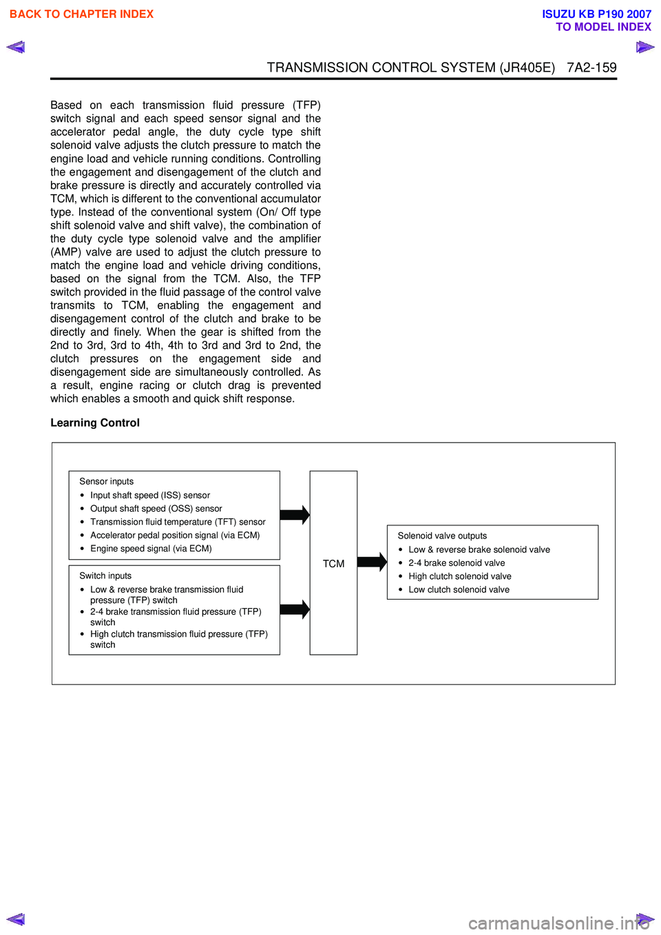
TRANSMISSION CONTROL SYSTEM (JR405E) 7A2-159
Based on each transmission fluid pressure (TFP)
switch signal and each speed sensor signal and the
accelerator pedal angle, the duty cycle type shift
solenoid valve adjusts the clutch pressure to match the
engine load and vehicle running conditions. Controlling
the engagement and disengagement of the clutch and
brake pressure is directly and accurately controlled via
TCM, which is different to the conventional accumulator
type. Instead of the conventional system (On/ Off type
shift solenoid valve and shift valve), the combination of
the duty cycle type solenoid valve and the amplifier
(AMP) valve are used to adjust the clutch pressure to
match the engine load and vehicle driving conditions,
based on the signal from the TCM. Also, the TFP
switch provided in the fluid passage of the control valve
transmits to TCM, enabling the engagement and
disengagement control of the clutch and brake to be
directly and finely. When the gear is shifted from the
2nd to 3rd, 3rd to 4th, 4th to 3rd and 3rd to 2nd, the
clutch pressures on the engagement side and
disengagement side are simultaneously controlled. As
a result, engine racing or clutch drag is prevented
which enables a smooth and quick shift response.
Learning Control
Solenoid valve outputs
Low & reverse brake solenoid valve
2-4 brake solenoid valve
High clutch solenoid valve
Low clutch solenoid valve
TCM
Sensor inputs Input shaft speed (ISS) sensor
Output shaft speed (OSS) sensor
Transmission fluid temperature (TFT) sensor
Accelerator pedal position signal (via ECM)
Engine speed signal (via ECM)
Switch inputs
Low & reverse brake transmission fluid
pressure (TFP) switch
2-4 brake transmission fluid pressure (TFP)
switch
High clutch transmission fluid pressure (TFP)
switch
BACK TO CHAPTER INDEX
TO MODEL INDEX
ISUZU KB P190 2007
Page 4457 of 6020
ON-VEHICLE SERVICE (JR405E) 7A3-3
Cold Level
The vehicle must not have been driven so that the
temperature reaches around 20 °C (68 °F) before the
cold level check is made.
1. Park the vehicle on a level surface.
2. Apply the parking brake firmly.
3. Start the engine and allow it to warm up.
The engine coolant temperature gauge needle should be midway between the “C” mark and “H”
mark.
4. Let the engine run at idle.
Move the select lever slowly through all the gea
r
ranges.
Stop in each range just long enough for the transmission to engage.
5. Return the select lever either “P” or “N”.
6. Remove the ATF level dipstick.
7. W ipe the dipstick clean with a paper towel.
8. Reinsert the dipstick and wait several seconds.
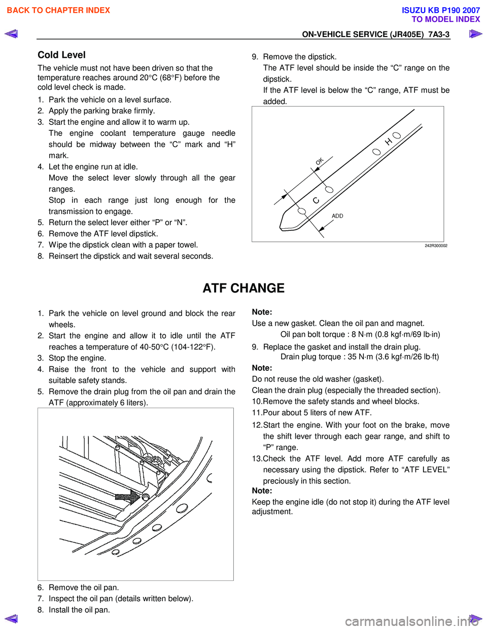
9. Remove the dipstick.
The ATF level should be inside the “C” range on the dipstick.
If the ATF level is below the “C” range, ATF must be added.
242R300002
ATF CHANGE
1. Park the vehicle on level ground and block the rear
wheels.
2. Start the engine and allow it to idle until the ATF reaches a temperature of 40-50 °C (104-122 °F).
3. Stop the engine.
4. Raise the front to the vehicle and support with suitable safety stands.
5. Remove the drain plug from the oil pan and drain the ATF (approximately 6 liters).
6. Remove the oil pan.
7. Inspect the oil pan (details written below).
8. Install the oil pan.
Note:
Use a new gasket. Clean the oil pan and magnet.
Oil pan bolt torque : 8 N ⋅m (0.8 kgf ⋅m/69 lb ⋅in)
9. Replace the gasket and install the drain plug.
Drain plug torque : 35 N ⋅m (3.6 kgf ⋅m/26 lb ⋅ft)
Note:
Do not reuse the old washer (gasket).
Clean the drain plug (especially the threaded section).
10.Remove the safety stands and wheel blocks.
11.Pour about 5 liters of new ATF.
12. Start the engine. W ith your foot on the brake, move the shift lever through each gear range, and shift to
“P” range.
13.Check the ATF level. Add more ATF carefully as necessary using the dipstick. Refer to “ATF LEVEL”
preciously in this section.
Note:
Keep the engine idle (do not stop it) during the ATF level
adjustment.
BACK TO CHAPTER INDEX
TO MODEL INDEX
ISUZU KB P190 2007
Page 4732 of 6020
Manual Transmission (MUX) 7B1-13
16. Install the front propeller shaft. (4x4 model)• Tighten the front propeller shaft bolts to thespecified torque.
Torque: 59 N ⋅m (6.0 kgf ⋅m/43 lb ⋅ft)
17. Install the rear propeller shaft.
• Tighten the rear propeller shaft bolts to thespecified torque.
Torque
Rear flange: 59 N ⋅m (6.0 kgf ⋅m/43 lb ⋅ft)
Center bearing: 69 N ⋅m (7.0 kgf ⋅m/51 lb ⋅ft)
18. Connect harness clip on the transmission left side bracket.
Install the harness bracket bolt.
• Tighten the harness bracket bolt to the specified torque.
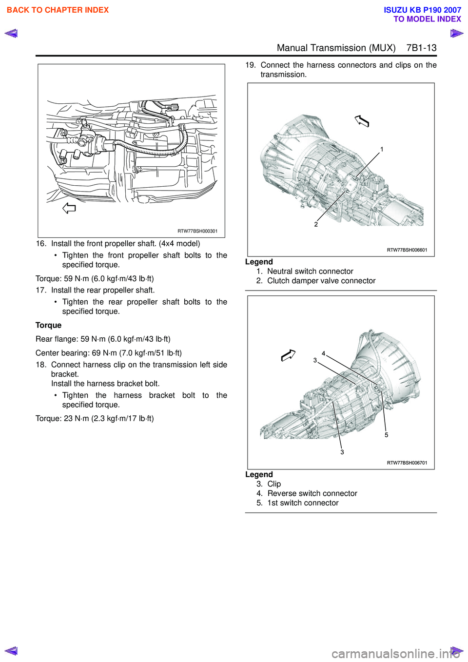
Torque: 23 N ⋅m (2.3 kgf ⋅m/17 lb ⋅ft) 19. Connect the harness connectors and clips on the
transmission.
Legend 1. Neutral switch connector
2. Clutch damper valve connector
Legend 3. Clip
4. Reverse switch connector
5. 1st switch connector
RTW77BSH000301
RTW77BSH006601
1
2
RTW77BSH006701
3
3 54
BACK TO CHAPTER INDEX
TO MODEL INDEX
ISUZU KB P190 2007
Page 4733 of 6020
7B1-14 Manual Transmission (MUX)
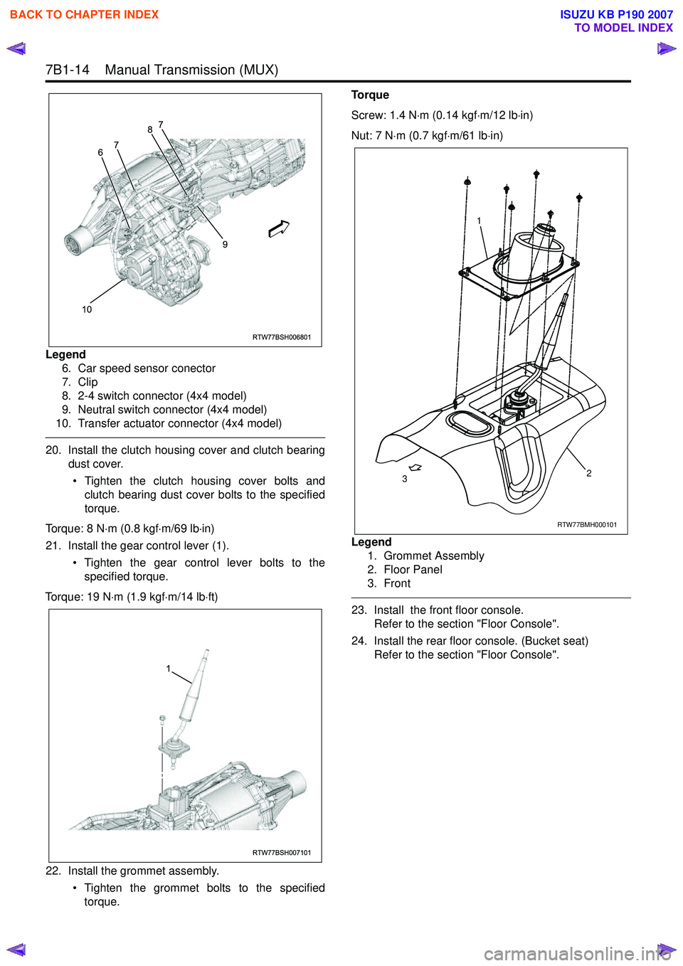
Legend6. Car speed sensor conector
7. Clip
8. 2-4 switch connector (4x4 model)
9. Neutral switch connector (4x4 model)
10. Transfer actuator connector (4x4 model)
20. Install the clutch housing cover and clutch bearing dust cover.
• Tighten the clutch housing cover bolts and clutch bearing dust cover bolts to the specified
torque.
Torque: 8 N ⋅m (0.8 kgf ⋅m/69 lb ⋅in)
21. Install the gear control lever (1). • Tighten the gear control lever bolts to thespecified torque.
Torque: 19 N ⋅m (1.9 kgf ⋅m/14 lb ⋅ft)
22. Install the grommet assembly. • Tighten the grommet bolts to the specifiedtorque. Torque
Screw: 1.4 N ⋅m (0.14 kgf ⋅m/12 lb ⋅in)
Nut: 7 N ⋅m (0.7 kgf ⋅m/61 lb ⋅in)
Legend 1. Grommet Assembly
2. Floor Panel
3. Front
23. Install the front floor console. Refer to the section "Floor Console".
24. Install the rear floor console. (Bucket seat) Refer to the section "Floor Console".
RTW77BSH006801
10 9
6
7 8
7
RTW77BSH007101
1
RTW77BMH000101
1
2
3
BACK TO CHAPTER INDEX
TO MODEL INDEX
ISUZU KB P190 2007